1
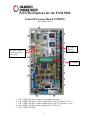
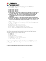
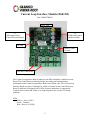
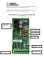
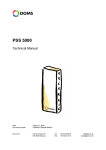
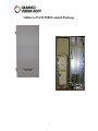
Gilbarco PAM 5000 Launch Package 1 Table of Contents Glossary of Abbreviations/Terms Manual References Tools Required System Overview What is a Gilbarco PAM 5000? Where/when is it used? Why the change? Features/Benefits Commissioning the Equipment Parts/Descriptions Parts Breakdown 2 Glossary of Abbreviations CPB- Central Processor Board CPU- Central Processing Unit DSB Module- Hardware Interface Module (HIM) for a connection via the Doms Serial Bus port DSB port- Port with Doms Serial Bus hardware interface. DSB ports are numbered 11,12,13,14,15 on the CPB board DMB Port- Port with Doms Multiplex Bus hardware interface. The DMB ports are numbered 21 to 23 on the CPB board. The port can also be used as a DSB Port by using a special DSMB cable DMB Module- DOMS Multiplex Hardware Interface Module Gilbarco PAM 5000- The latest interface system that replaces the PAM 1000 HIM- Hardware Interface Module (DSB/DMB) LAN- Local Area Network PAM- Pump Access Module PORT- A physical serial communication port for connection to hardware modules POS- Point of Sale PSU- Power Supply Unit Service Port- A communication port for connection of a service PC or laptop via an RS-232 connection via null-modem cable wiring WAN- Wide Area Network Manual References MDE- 4676 PAM 5000 Installation Manual MDE- 4677 PAM 5000 Service Manual MDE- 3802 Encore & Eclipse Site Prep Manual MDE-3804 Encore & Eclipse Start-up and Service Manual MDE-3893 Encore/Eclipse Owners Manual MDE- 4185 Encore/Eclipse CRIND BIOS Configuration Interface Manual Tools Required for Installation Large Slotted Screwdriver Small (max 2.5.mm) Slotted Screwdriver Drill & Fasteners (to secure PAM 5000 to wall) 3 System Overview This Launch Package is to help familiarize you with the Gilbarco PAM 5000. This document should not be used as a replacement for parts, service, or installation manuals. In this Launch Package you will find a list of documents (Manual References listed above) related to the Gilbarco PAM 5000 that should be used for reference should more information be needed. These documents should be used when performing service work of any kind on this product. All of the listed documents can be found on the Gilbarco website GOLD on the Gilbarco Extranet (www.gilbarco.com). Always use the most current documentation when servicing this product. What is a Gilbarco PAM 5000? The PAM 5000 is a system based on the Gilbarco PAM 1000 Controller. It will be able to replace the old system with full compatibility. The PAM POS protocol is based on the PAM 1000 software version 32.1.60 and PAM 1000 Interface specification. The PAM 5000 will support the PAM protocol using different communication speeds (300-19200 baud rate) and different protocol options (24 or 36 Pump support). The physical serial interface to the POS is based on Hardware Interface Module (HIM) DSB 500 supporting RS232/RS422 or CL 45mA passive, selectable at the wiring time. By default the PAM 5000 basic system will handle up to 16 fueling positions. For sites swapping out the PAM 1000 for the PAM 5000 and the D/Box is reused, the default can be changed to12 fueling positions per PAM port. An extra CL hardware interface module would be needed if the number of fueling points is higher than 12. For new sites the default will be 16 fueling points per PAM port with the third board then supporting 4 fueling points if needed. The physical connection is made with a Gilbarco HIM module DSB492 (maximum of eight dispensers or 16 fueling positions per module). The system will come with the necessary DSB500 and DSB492 modules per the sites configuration. If the site has more than 16 fueling positions then another DSB492 module will be needed. The system would just need a simple setup change to the PAM configuration and no software upgrade would be necessary. The PAM 5000 is replacing the PAM 1000 because parts for the PAM 1000 are going end-of-life and will become obsolete by the summer of 2008. 4 Features/Benefits of the PAM 5000 Better performance Simple & easy to expand Ethernet connection and Service port (RS-232) with TCP/IP available for remote service and monitoring Built in web server Easy software update to flash memory No jumpers needed. All changes made via web, locally or remote Local display for service and status monitoring Devices can be monitored on the local display or via web Port statistics (errors) can be monitored Transaction and device status monitoring Port communication log (Can see which ports are communicating) Adds remote diagnostics to troubleshoot POS to PAM issues Allows elimination of the Distribution Box Commissioning the Equipment Before leaving the site you must commission the equipment so that the warranty can start. Failure to do so will cause problems with attempting to open/close service and calls and getting paid for work completed thereafter. Please call 1-888-800-7498 and listen to the menu and select the Commissioning option. 5 Parts/Descriptions for the PAM 5000 Central Processor Board (CPB509) Part # M08037B010 18. JTAG Interface (Not used) 19 & 20- Sockets for LON options (not used) 15. Display 1. 2. 3. 4. 5. Port 11 DSB- This port is used for connecting to the PAM Port 12 DSB- This port is used for pump loop #1 (FP1-16 default or 1-12) Port 13 DSB- This port is used for pump loop #2 (FP17-32 default or 13-24) Port 14 DSB- This port is used for pump loop #3 (FP33-36) Port 15 DSB- Not used 6 6. Port 21 DMB- This port is used supplying power for CRIND loop #1 7. Port 22 DMB- Not Used 8. Port 23 DMB- Not Used 9. Port 31 LON- Not Used 10. Port 32 LON- Not Used 11. Port 41 Ethernet- This port has an Ethernet cable connecting to it, which leads to an external Ethernet port. That is used for downloading software to the CPB. 12. Port 1/Service Port- This is a RS-232 connection that can also be used for downloading software to the CPB. It can also be used for Servicing and Diagnostics 13. Power Supply Connector- 3-Pin connector from the Transformer connects here 14. Keyboard- The CPB has a 5-key keyboard called a local service panel that is used to access some programming if a laptop is not available. * Does not access all programming 15. Display- The display is used in conjunction with the keyboard so programming options can be seen 16. Test Connector- This connector is not used 17. BDM Connector- This connector is not used 18. JTAG Interface- This connector is not used at this time 19. & 20- Sockets for LON options (These are not used at this time) The CPB is a microprocessor-based controller for use in the PAM 5000 forecourt controller system. It is equipped with the following: 5 DSB ports 3 DMB ports 1 Ethernet interface 2 LON interfaces (add on options) 16MB Flash memory for application software 4MB SRAM for data memory A keyboard consisting of 5 keys together with a 32-character LCD display makes it possible to adjust and monitor several parameters without the need for connecting an external PC. A battery is used for data and real-time clock in case of a power failure. 7 Current Loop Interface Module (DSB 492) Part # M08037B001S Power LED J1 DSB connection to Central Processor Board J2 DSB connection to another module TX LED Receive LEDs (8) total Two-Wire connections The Current Loop Interface Board connects to the DIN-rail and the Central Processor Board. The Central Processor Board provides the voltage and communication information to the Current Loop Interface Board via a ribbon cable. The Current Loop Interface Board uses ports 12 through 14, which are located on the Central Processor Board. Each board is equipped with 8 LEDs for status indications. It supports the required 45ma needed, and 8 dual or 16 single dispensers for a total of 16 fueling positions. LEDs Yellow = Power (VDC) Green = Transmit Red = Receive (8 LEDs) 8 VDC indicates power is present. TX is flashing when data is transmitted from the DSB 500 and the RX is flashing if data is received from the connection. The DSB492 drives a total load of 5.0-volt idle voltage. This voltage makes the sum of the idle-pump-load, the connection wire drop and the noise margin. RS-232/RS-422/CL Interface Module (DBS 500) Part # M08037B002S Connection to the Central Processor Board. *Must plug into Port 11 Power LED (Yellow) Transmit LED (green) Receive LED (red) CL 45mA passive POS connection RS-422 POS connection T+, T-, R+, R- RS-232 POS connection TX, RX, GND 9 This module is the interface between the POS and the Central Processor Board. It supports communication baud rates for the POS between 300 and 19200. This module supports RS-232 (any runs between the PAM 5000 and the POS longer that 50ft. require a line booster) as well as RS-422, current loop 45 mA, which if the POS supports it can run much longer distances without needing a line booster. PAM 5000 Parts Breakdown Gilbarco Part # M08037B003 M08037B004 M08037B005 M08037B006 M08037B007 M08037B008 M08037B009 M08037B010 M08037B011 M08037B012 M08037B002S DOMS Part # 140718 138484 141636 126678 135695 133088 140109 138552 135547 135391 141662 M08037B001S 140042 Q11121 02 141666 Q11736 03 R19000-02 R19000-03 R19000-04 PA03820000 138243 Description Fuse, slow blow, 5x20mm, 1A, IEC127-2/3 Fuseholder, for insertion in AC inlet PAM CRIND Cross Ribbon Cable DSMB no 42 DSB-cable mini, 2.7“/ 7cm, DSB no 23 DSB-cable 7.8” / 42cm, DSB no 33 AC Filter without fuse holder (add M8037B004 to complete) Power Supply Transformer, 120V/24V, 36VA, toroid Central Processor Board (CPB509) Internal Ethernet Cable, 25”/65cm (CBL311 type 001) Ethernet Connection Board (DCB460) RS232/RS422/CL interface module (DSB500) Current Loop 45mA Interface Module, 8 connections (DSB492) Power Cord, grounded US plug NEMA 5-15, IEC320, 78” / 2m black Power Cord without plug for wall end, IEC320, 59” /1.5m black PVC Pigtail for PAM to D-Box cable Pigtail for POS to PAM cable Pigtail for PAM to D/Box cable (CRIND Control) PAM 5000 10