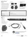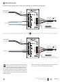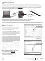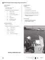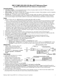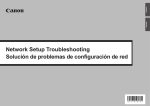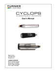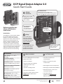
1
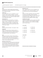
TM
DCP Signal Output Adapter 2.0
Quick Start Guide
Mini USB Connector
Provide power to the adapter, and
passthrough communication to the attached
sonde. See page 4 for USB passthrough info.
Adapter
Overview:
Supply Power, 12VDC
Provided from external
regulated power source
(not included).
Delivering quality data
where and when you
need it most.
Introduction:
The 599820 is a communication adapter
for the EXO multiparameter sonde
platform. It converts the proprietary
signal from the water quality sonde into
either SDI-12 or RS-232 signals. The
adapter simplifies integration into 3rd
party DCP systems, and also features
a USB port that supports passthrough
communication directly to the connected
sonde. This feature allows configuration,
calibration, and data transfer without
having to disconnect the field cabling.
Specifications
Supply Voltage: 9 - 16 VDC or
USB 5 VDC
Current Draw Adapter:
~20mA typical (@12VDC)
Current Draw Sonde: ~sleep 0.25mA
reading and 100mA during operation
Max Net Current Draw for Systems:
~200mAmps (@12VDC)
Dimensions: L=3.5”, W=3.5”, H=1.5”
(89cm x 89cm x 38cm)
Operating Temp: -40°C to +60°C
Storage Temp: -50°C to +80°C
SDI-12 & RS-232
I/O Terminal
Use either SDI-12 or
RS-232 terminals.
Status LED
See page 2 for
status indications.
Safety:
Refer to EXO system
manual for complete
safety documentation
associated with the EXO
system. (Available at
EXOwater.com)
Follow all applicable code
and regulations subject
to electrical wiring and
operation of the system.
Magnetic Read Switch
Used to rediscover
attached sonde.
What’s Included:
You’ll also need:
Your new 599820 EXO Communication
Adapter comes with:
• Flat blade screwdriver for
terminal blocks
• (1) DCP 2.0 Adapter
• Phillip’s screwdriver for panel
mount bracket
• (3) green wiring terminal blocks
(Sonde 5-pin, Power 2-pin,
DCP 7-pin)
• EXO magnetic sensor tool (optional)
• (1) Panel mounting bracket
• EXO Flying Lead Field cable (599008-x)
• (1) Hook and loop fastener
• EXO sonde system, sensors, and
associated hardware
If any item is missing, please contact
[email protected] for replacements.
• Latest KOR software
(available from EXOwater.com)
(KOR 2.0 available Q1 of 2016)
Humidity: 0 to 99% non-condensing
1
item# 599932REF dwg# 599932
November 2015 Rev A
YSI.com
Getting Started
Mounting:
The adapter should be protected from
the elements, and it is recommended it
be mounted inside of a sealed enclosure
with desiccant to prevent condensation.
The adapter includes a panel mount in
addition to self-adhesive hook and loop
fastener. Either of these two methods
can be used to securely mount the
adapter. Use the provided Phillips
screw to secure the panel mount:
Panel Mount
Self-Adhesive Hook and
Loop Fastener
1:
2:
Note: If using self adhesive hook
and loop, clean and dry both
surfaces before applying.
Back
Front
Status LED Indications
Off
No power
On
No Sonde connected
Flashing at 1 Hz
Sonde connected, everything normal
Flashing at 1/10 Hz
Low power sleep (Will flash on for 1 second when magnetic switch is activated.)
Wiring
Have the
following ready:
• EXO Sonde
• DCP 2.0 Adapter
• Flying Lead Cable
• Desiccant if using Vented Cable
• Flat blade screwdriver
• Power & Data Logger Wires
See next page for wiring diagrams.
2
Webinar | A Simple Guide to Collecting Water Quality Data
Learn the basics of wiring your Sonde up to a DCP:
https://goo.gl/B4PPK7
item# 599932REF dwg# 599932
November 2015 Rev A
YSI.com
Wiring Continued
Next wire the flying lead cable, power, and DCP ports as labeled in one of the following configurations:
Regulated 12VDC
power supply
(not included)
1 AMP
fast-blow fuse
Flying Lead
Cable 599008-x
Vented
599210-x
Cable to Water
Quality Sonde
To Datalogger
Wave EXO sensor tool magnetic
activator here to rediscover the sonde.
OR
Regulated 12VDC
power supply
(not included)
1 AMP
fast-blow fuse
Flying Lead
Cable 599008-x
To Datalogger
Vented
599210-x
Cable to Water
Quality Sonde
Wave EXO sensor tool magnetic
activator here to rediscover the sonde.
When connecting new sondes to the DCP adapter,
it may be necessary to redetect the sonde. This can
be done by power cycling the adapter or by using
the magnetic read switch at the lower right hand side of
the enclosure. Waving the magnet in the EXO sensor tool,
over the area referenced by the square above, will force a
network redetect where all new sensors and configurations
will be discovered.
3
Note: The orange wire on the flying lead cable to the sonde will
not be used. It can be taped back during installation.
item# 599932REF dwg# 599932
November 2015 Rev A
YSI.com
USB Passthrough Mode
The 599820 DCP Signal Output Adapter can function in a similar fashion as the 599810 USB communication adapter. After the
Signal Output Adapter is wired as shown in the previous configuration, connecting to the USB port on the adapter will allow direct
communications with the sonde using KorEXO software. USB passthrough drivers will automatically be installed along with KOR 2.0
software, they are also available separately from the EXOwater.com website. Install these drivers on your PC to communicate with a
signal output adapter (SOA) through any version of Desktop KOR:
Note: USB utilizes Communication Device Class (CDC) and installs as com port on PC: “YSI SOA/DCP Gen2”.
The USB connection may also be used to update firmware on the adapter using KOR software.
Output Configuration
Output Parameters
In order to appropriately setup a sonde to communicate
measurements to a datalogger, it is critical to align the
settings from the sonde and the logger.
In the KorEXO software |Deployment Settings| choose the
parameters and sort order, then push the template to the
sonde. (Kor Version 1.0 shown on the top-right, and KorEXO
version 2.0 shown above on the bottom-right.)
In both versions the complete list of parameters is shown in
the left column and the selected parameters to output via
the DCP 2.0 adapter are shown on the right. This template
can be saved locally on the PC, but it must also be pushed
down to the sonde for the settings to take effect. So be sure
to apply the template to the sonde.
Kor Version 1.0
Note: there are two options when applying the template
to the sonde, apply without logging or with logging. Either
option may be used. When deploying with logging the sonde
will create a redundant log file inside the sonde. Without
logging the only data will be available to the RS-232 or
SDI-12 outputs.
Output Parameters
For access to the beta software, or assistance
changing the default settings, please contact
Technical Support at [email protected].
(Note: KorEXO software still in development,
screen will change in final release.)
4
KorEXO Version 2.0.x
item# 599932REF dwg# 599932
November 2015 Rev A
YSI.com
EXO DCP Signal Output Adapter Programming Basics
1. SDI-12 Interface
2. RS-232 Interface
• General
• General
• Compatible with v1.3 of
SDI-12 specification
• Command Line
• ‘#’ is user prompt
• Supports following standard commands:
• ‘!’
• Commands are not case senstive
Address Query
• ‘A’
• Only spaces are recognized as delimiters
Change Address
• ‘C’
• A command is terminated by a <CR><LF>
Concurrent Measurement
• ‘D’
Data
• Minimum time from power up to valid readings is 19 seconds
• ‘I’
Identification
• ‘M’
Start Measurement
• Command List
• ‘V’
Start Verification
See RS-232 commands on page 6.
See Port Settings on page 7.
• Extended Commands
• SDI-12 ‘Z’ command
• Supports the following RS232 commands:
• ‘sn’
Serial Number
• ‘para’
Parameter List
• ‘twipeb’ Start wipe
• ‘ver’
S/W version
• ‘ssn’
Sensor Serial Numbers
An example of a NEMA enclosure where
the DCP Signal Output Adapter is wired.
5
item# 599932REF dwg# 599932
November 2015 Rev A
YSI.com
RS-232 Command List
[ ] indicates argument is optional
<i> indicates argument is an integer
data
Returns one line of data readings. Data parameters
specified in para command. Data delimiter is specified
in the setdelim command.
pwruptorun [<i>]
Turns “power up to run” on if <i>=1 and off if <i>=0.
The response is “OK”. If you do not supply <i>, then
the response is the current value of pwruptorun.
dowait [<i>]
Turns “wait for DO” on if <i>=1 and off if <i>=0. The
response is “OK”. If you do not supply <i>, then the
response is the current value of dowait. When enabled
the SOA/DCP will not return data until sonde has been
on for “dowarmup” seconds.
run
Causes the sonde to SOA/DCP to take sonde readings
at a 1Hz rate. The output is similar to the Data
command except that readings are taken continuously.
No headers are output. To abort send ‘0’, <esc>, or
turn power off to the SOA/DCP and then reapply.
dowarmup [<i>]
Sets DO sensor warmup time where <i>=warmup
time in seconds. The response is “OK”. If you do not
supply <i>, then the response is the current value
for dowarmup. When “dowait” is enabled the SOA/
DCP will not return data until sonde has been on for
“dowarmup” seconds.
setcomm [<i1>] [<i2>]
Changes the SOA/DCP’s comm port baud rate and data
length. The baud rate will be immediately changed
after this command, so you will need to reconfigure
your terminal to match.
fltreset
Resets all sonde sensor filters. The response is “OK”.
hwipesleft
Returns a value other than 0 if a wiper event is in
progress. The value returned is normally the amount
of “half” wipes that are left to go. When wiping is
completely finished, the value will go to 0.
para
Returns the parameter numbers of all parameters
selected for output. Each number returned matches
one for one with the values returned in the data
command. The numbers are space delimited. Refer to
section 3 for list of parameter codes.
para [<i1> <i2> <i3> <i4> …]
Sets the data parameter codes used with the data and
run commands. The parameters are space delimited.
Refer to section 4 for the list of parameter codes. If
you do not supply any parameters then the response
is the current list of parameters. Maximum number of
parameters is 32.
6
<i1> can be:
2 - 1200 baud
6 - 19200 baud
3 - 2400 baud
7 - 38400 baud
4 - 4800 baud
8 - 57600 baud
5 - 9600 baud
9 - 115200 baud
<i2> can be:
0 - 7 bits
1 - 8 bits
RS-232 Command List Continued on next page.
item# 599932REF dwg# 599932
November 2015 Rev A
YSI.com
RS-232 Command List, Continued
setdelim [<i>]
Changes the SOA/DCP’s delimiter used in the data
command response. If you do not supply <i>, then
the response is the current value for delimiter.
<i> can be: 0 = space, 1 = TAB, 2 = comma, 3 = none
setecho [<i>]
Enables (<i>=1) or disables (<i>=0) command
echoes. When echoes are disabled, commands sent
to the SOA/DCP will not be ‘echoed’ back and there
will be no ‘# ‘ prompt. If you do not supply <i>, then
the response is the current value for echo.
setmode [<i>]
Sets the RS232 mode. If <i>=0, mode is normal. If
<i>=1 mode is NMEA. If you do not supply <i>, then
the response is the current value for mode.
setradix [<i>]
Sets the radix point used for data output. If <i>=0
radix will be ‘.’. If <i>=1 radix will be ‘,’. Note that in
SDI12 mode, the response to a ‘D’ command will
always be with ‘.’ regardless of this setting. The
response is “OK”. If you do not supply <i>, then the
response is the current value for radix.
setperiod [<i>]
Sets the period for the data output in RUN mode.
The period is set to <i> milliseconds. Minimum
value is 250 (1/4 second), maximum value is 30000
(30 seconds). If you do not supply <i>, then the
response is the current value for period. For periods
less than 1000 and baud rates below 9600, the data
output may be unreliable.
time [<hh:mm:ss>]
Allows user to set time in the sonde in the
HH:MM:SS format. The response is “OK”. If you do
not supply <hh:mm:ss>, then the response is the
current value of time.
twipeb
Starts a wiper event. The response is the
approximate time in seconds it will take to perform
the wipe.
ver
Returns the software version number of the sonde.
verdate
Returns the time and date at which the current
version of software in the sonde was compiled.
setsonde [<i>]
Selects a sonde for RS232 communications
when more than 1 sonde are daisy-chained. <i>
represents the order of the sonde in the chain
where 1st sonde = 0, 2nd = 1, 3rd = 2. The response
is “OK”. If you do not supply <i>, then the response
is the current value for sonde.
sn
Returns the unique serial number programmed into
every YSI sonde.
ssn
Returns the unique serial number for the sonde and
all attached sensors
RS-232 settings should
resemble this image.
7
item# 599932REF dwg# 599932
November 2015 Rev A
YSI.com
Available Parameter Codes
For reference, below are the available parameter codes:
• All codes below 223 are 6-series compatible (except TSS).
• Maximum of 23 codes in sonde parameter list.
Parameter
Code
Parameter
Code
Parameter
Code
Temperature, °C
1
Date, DDMMYY
51
Turbidity, FNU
223
Temperature, °F
2
Date, MMDDYY
52
Turbidity, Raw
224
Temperature, °K
3
Date, YYMMDD,
53
BGA-PC, ug/L
225
Conductivity, mS/cm
4
Time, HHMMSS
54
BGA-PE, ug/L
226
Conductivity, uS/cm
5
TDS, kg/L
95
fDOM, RFU
227
Specific Conductance, mS/cm
6
NO3 (Nitrate), mV
101
fDOM, QSU
228
Specific Conductance, uS/cm
7
NO3 (Nitrate), mg/L
106
Wiper Position, V
229
TDS, g/L
10
NH4 (Ammonium), mV
108
External Power, V
230
Salinity, PPT
12
TDS, mg/L
110
BGA-PC, Raw
231
pH, mV
17
Chloride, mg/L
112
BGA-PE, Raw
232
pH
18
Chloride, mV
145
ORP, mV
19
TSS, mg/L
190
fDOM, Raw
233
Pressure, psia
20
TSS, g/L
191
Chlorophyll, Raw
234
Pressure, psig
21
Chlorophyll, ug/L
193
Depth, m
22
Chlorophyll, RFU
194
Depth, ft
23
ODO, %Sat
211
Battery, V
28
ODO, mg/L
Turbidity, NTU
37
NH3 (Ammonia), mg/L
NH4 (Ammonium), mg/L
Potassium, mV
†
235
Potassium, mg/L
†
236
NLF Conductivity, mS/cm
237
212
NLF Conductivity, uS/cm
238
ODO, %Sat Local
214
Wiper Peak Current, mA
239
47
BGA-PC, RFU
216
Vertical Position, m
240
48
BGA-PE, RFU
218
Vertical Position, ft
241
† Note: Potassium is considered future functionality, there is currently no EXO probe for Potassium (as of 2015).
8
item# 599932REF dwg# 599932
November 2015 Rev A
YSI.com