1
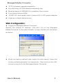
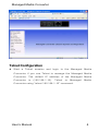
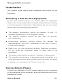
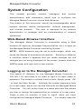
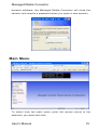
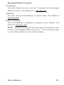
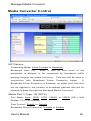
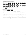
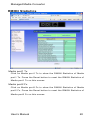
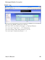
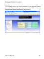
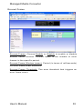
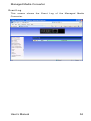
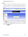
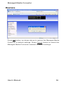
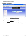
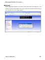
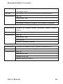
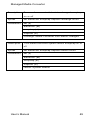
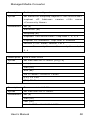
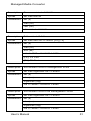
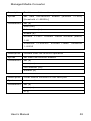
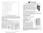
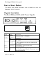
Managed Media Converter Quick Start Guide This quick start guide describes how to install and use the Managed Media Converter. Physical Description The Port Status LEDs and Power Inputs LEDs State Steady (Green) PW/FA Power on, PW = POWER Off Power off Steady The device is booting up or failed (Orange) Steady LK/AT Indication Flashing (Green) FA = FAIL A valid network connection established LK = LINK Transmitting or receiving data AT = ACTIVITY Valid network connection is not established Off and the Managed Media Converter is not transmitting data User’s Manual 1 Managed Media Converter Steady FD/CL (Orange) Flashing Off Connection in full-duplex mode FD = FULL-DUPLEX Collision occurred CL = COLLISION Connection in half-duplex mode Physical Description z One-channel media conversion between 10/100Base-TX and 100Base-FX z Multi-mode fiber using SC, ST, VF-45, MT-RJ, or LC connector z Single-mode fiber using SC or ST connector z WDM single-fiber (bi-direction) transceiver, single-mode fiber using SC connector: A type: WDM single-fiber (bi-direction) transceiver transmits with 1310nm wavelength and receives with 1550nm wavelength B type: WDM single-fiber (bi-direction) transceiver transmits with 1550nm wavelength and receives with 1310nm wavelength z Auto negotiation of speed and duplex mode on TX port z Auto MDIX on TX port z 1024 MAC addresses, 256K bits buffer memory z One push button to reset the Managed Media Converter to default IP address z Complies with IEEE802.3ah OAM CPE (Customer Premise Equipment) standard z Supports VLAN & IEEE802.1Q Tagged VLAN z Supports broadcast storm protection z Provides MAC address filtering z SNMP, Web-based, Telnet, and RMON management z Alarm by Mail-Trap and SNMP-Trap User’s Manual 2 Managed Media Converter z TFTP firmware-upgrade capability z Non-blocking full wire-speed forwarding rate z Back-pressure & IEEE802.3x compliant flow control z Front panel status LEDs z 12VDC DC Jack power input, external AC to DC power adapter z Used as a stand-alone device Web Configuration z Login the Managed Media Converter: Specify the default IP address (192.168.1.10) of the Managed Media Converter in the web browser. A login window will be shown as below: z Enter the factory default user name (no user name). Enter the factory default password (no password). Then click on the “OK” button to log on to the Managed Media Converter. User’s Manual 3 Managed Media Converter Telnet Configuration z Start a Telnet session and login to the Managed Media Converter if you use Telnet to manage the Managed Media Converter. The default IP address of the Managed Media Converter is (192.168.1.10). Telnet to Managed Media Converter using “telnet 192.168.1.10” command. User’s Manual 4 Managed Media Converter z Default login is “null” and default password is “null”. z Type in “?” or “h” to get help screen for all of the Telnet commands. User’s Manual 5 Managed Media Converter Preface The Managed Media Converter can be monitored and configured, through management via SNMP, Web-based, and Telnet. This manual describes how to configure the Managed Media Converter. To get the most out of this manual, you should have an understanding of networking concepts such as bridging, IEEE 802.3 10Base-T Ethernet, IEEE802.3u 100Base-TX/100Base-FX Fast Ethernet, and local area networks (LANs). In this manual, you will find: z Product overview z Features of the media converter z Illustrative LED functions z Installation instructions z System configuration z Technical specification User’s Manual 6 Managed Media Converter Table of Contents Quick Start Guide...............................................................1 Physical Description .......................................... 1 The Port Status LEDs and Power Inputs...............1 Physical Description .......................................... 2 Web Configuration ............................................ 3 Telnet Configuration .......................................... 4 Preface ......................................................................................6 Table of Contents...............................................................7 Introduction ............................................................................9 Product Overview .............................................. 9 Product Features .............................................. 9 Packing List .................................................... 10 One-Channel Media Converter...............................11 Ports............................................................... 11 Front Panel & LEDs......................................... 11 LED Indicators.......................................................................11 Installation ...........................................................................12 Selecting a Site for the Equipment ................... 12 Connecting to Power ....................................... 12 System Configuration ...................................................14 Web-Based Browser Interface ......................... 14 Logging on to the Managed Converter ............. 14 Main Menu ...................................................... 15 System Change ....................................................................16 IP Configuration ...................................................................17 Media Converter Status ..................................................19 Media Converter Control................................................20 RMON Statistics...................................................................22 MAC Address Filter............................................................23 User’s Manual 7 Managed Media Converter VLAN Configuration...........................................................24 SNMP Configuration .........................................................26 Alarm............................................................................................27 OAM..............................................................................................30 Save..............................................................................................35 Restore .......................................................................................36 Update Firmware .................................................................37 Reboot ........................................................................................38 Technical Specification ...............................................39 Appendix A – Telnet command set ......................40 User’s Manual 8 Managed Media Converter Introduction The Managed Media Converter provides one channel for media conversion between 10/100Base-TX and 100Base-FX. It can be used as a stand-alone device. Product Overview Product Features z One-channel media conversion between 10/100Base-TX and 100Base-FX z Multi-mode fiber using SC, ST, VF-45, MT-RJ, or LC connector z Single-mode fiber using SC or ST connector z WDM single-fiber (bi-direction) transceiver, single-mode fiber using SC connector: A type: WDM single-fiber (bi-direction) transceiver transmits with 1310nm wavelength and receives with 1550nm wavelength B type: WDM single-fiber (bi-direction) transceiver transmits with 1550nm wavelength and receives with 1310nm wavelength z Auto negotiation of speed and duplex mode on TX port z Auto MDIX on TX port z 1024 MAC addresses, 256K bits buffer memory z One push button to reset the Managed Media Converter to User’s Manual 9 Managed Media Converter default IP address z Complies with IEEE802.3ah OAM CPE (Customer Premise Equipment) standard z Supports VLAN & IEEE802.1Q Tagged VLAN z Supports broadcast storm protection z Provides MAC address filtering z SNMP, Web-based, Telnet, and RMON management z Alarm by Mail-Trap and SNMP-Trap z TFTP firmware-upgrade capability z Non-blocking full wire-speed forwarding rate z Back-pressure & IEEE802.3x compliant flow control z Front panel status LEDs z 12VDC DC Jack power input, external AC to DC power adapter z Used as a stand-alone device Packing List When you unpack this product package, you will find the items listed below. Please inspect the contents, and report any apparent damage or missing items immediately to your authorized Etherwan reseller. z The Media Converter z User’s Manual z AC to DC Power Adaptor User’s Manual 10 Managed Media Converter One-Channel Media Converter Ports The Converter provides one TX port and one FX port. The FX port may be specified in the following options: Multi-mode fiber using SC, ST, VF-45, MT-RJ, or LC connector or Single-mode fiber using SC or ST connector or WDM fiber using single SC connector The TX port is an RJ-45 connector and auto senses the speed of 10/100Mbps. Front Panel & LEDs LED Indicators The LED indicators provide instant feedback on status of the converter: LEDs State Steady (Green) PW/FA Power on, PW = POWER Off Power off Steady The device is booting up or failed (Orange) FA = FAIL Steady LK/AT Indication Flashing (Green) A valid network connection established LK = LINK Transmitting or receiving data AT = ACTIVITY Valid network connection is not established Off and the Managed Media Converter is not transmitting data Steady FD/CL (Orange) Flashing Off User’s Manual Connection in full-duplex mode FD = FULL-DUPLEX Collision occurred CL = COLLISION Connection in half-duplex mode 11 Managed Media Converter Installation This chapter gives step-by-step installation instructions for the Converter. Selecting a Site for the Equipment As with any electric device, you should place the equipment where it will not be subjected to extreme temperatures, humidity, or electromagnetic interference. Specifically, the site you select should meet the following requirements: z The ambient temperature should be between 32 and 113 degrees Fahrenheit (0 to 45 degrees Celsius). z The relative humidity should be less than 95 percent, non-condensing. z Surrounding electrical devices should not exceed the electromagnetic field (RFC) standards for IEC 801-3, Level 2 (3V/M) field strength. z Make sure that the equipment receives adequate ventilation. Do not block the ventilation holes on each side of the equipment. z z The power outlet should be within 1.8 meters of the product. The installer should wear a grounding strap connected to a solid electrical ground when handling the Converter and when plugging and unplugging the TX port connector. Connecting to Power Connect the supplied AC to DC power adaptor to the receptacle on the rear panel of the converter, and then attach the plug into a standard AC outlet. User’s Manual 12 Managed Media Converter User’s Manual 13 Managed Media Converter System Configuration This chapter provides network managers and system administrators with information about how to configure the Managed Media Converter via the Web Browser. The reader of this document should be knowledgeable about network devices, device configuration, network management, and Internet browser. The user is assumed to be network administrator or manager with an understanding of network operations. Web-Based Browser Interface The Managed Media Converter is accessible using a Web browser (IE explorer, Netscape Communication, etc.) to open up the Managed Media Converter monitoring System. NOTE: WEB browsers may be set to cache pages, which can cause the display of erroneous information. Should you observe a condition where it appears that you made changes but the changes are not being displayed on the screen, please close the WEB browser and login with a new session. Logging on to the Managed Converter The default IP Address for the Managed Media Converter is 192.168.1.10, and there is no need to type in a Login name or password. The default is a blank field for both. Simply press ‘ OK ‘ to start the Main Screen. Although the system displays a field for a user name, we do not use this field with the Managed Media Converter. You will notice there is a menu selection that allows the user to change the password but no mention of a user name. There is also no mention of how to logoff, when you have configured the Managed Media Converter. User’s Manual You simply close the 14 Managed Media Converter browser software; the Managed Media Converter will close the session and require a password when you open a new session. Main Menu To select from the main menu, point the mouse cursor to the selection you want and click. User’s Manual 15 Managed Media Converter System Change The following is a screen shot of the System Change Menu: Device Name The user may set a Device Name for this Managed Media Converter by typing a name into this field. New Password This field allows you to set a new password for login. Type a new password into this field. Old Password If you set a new password you must type the old password into this field. NOTE: Press the Apply button to change the password. The apply button applies the changes for a specific screen, but does not save those changes to non-volatile memory. The user MUST select SAVE to store any and all changes to non-volatile memory before they end a management session. Version This is an indication of the Software version for reference. User’s Manual 16 Managed Media Converter MAC Address The factory assigned MAC address for the Converter is displayed in this field. IP Configuration The following is a screen shot of the IP Configuration field: DHCP Set the DHCP ‘ Enable ‘ or ‘ Disable ‘. If DHCP is enabled the Managed Media Converter will obtain its IP address from a DHCP server. The IP obtained from a DHCP server will replace any IP that has been manually loaded. NOTE: The user should be careful with DHCP because managing the Managed Media Converter depends on knowing its IP address. If a DHCP server has assigned the IP, it becomes a dynamic IP and managing the Managed Media Converter must then become a dynamic process or you will have to continually look up the address from the DHCP server. User’s Manual 17 Managed Media Converter IP Address This field allows the user to set an IP address for the Managed Media Converter. The default IP is 192.168.1.10 . Netmask The user may set the Netmask or subnet mask. The default is 255.255.255.0. Default Gateway This is the address of a gateway, if present in your network. The default is 192.168.1.254 . NOTE: Pressing the Apply button will apply the settings on this screen to the Managed Media Converter. You must press Save to store these settings to non-volatile memory. User’s Manual 18 Managed Media Converter Media Converter Status Operation Status Normal, Hardware fault or Software fault Media Port1: 10/100TX Link Status, Receive Count, CRC Count, Drop Count or Collision Count Media Port2: 100FX Link Status, Receive Count, CRC Count, Drop Count or Collision Count NOTE: If the Status needs to be calculated from fresh, please press the Reset button to restart the counting. User’s Manual 19 Managed Media Converter Media Converter Control MC Options Forwarding Mode: Store-Forward or Repeater. Broadcast Limit (%): Enter a limit for how much of the bandwidth is allowed to be consumed by broadcast traffic passing through the media converter. This limit will be used in conjunction Protection with Broadcast Storm below. If Broadcast Storm Protection is Enabled, for either port, this limit will be applied to the number of broadcast packets that will be allowed to pass through the Managed Media Converter. Media Port1 (Type: 10/100TX) Port Mode: Auto , 10HD , 10FD, 100HD, or 100FD (HD = Half Duplex, FD = Full Duplex) Flow Control: Enable or Disable Broadcast Storm Protection: Disable or Enable User’s Manual 20 Managed Media Converter Output Rate: Full , 6%, 12% , 18%, 24% , 30% , 36%, 42% , 48%, 54% , 60%, 66% , 72% , 78%, 84%, or 90% Input Rate: Full , 6%, 12% , 18%, 24% , 30%, 36% , 42%, 48%, 54% , 60%, 66% , 72% , 78%, 84%, or 90% NOTE: If Output Rate or Input Rate is set to any setting other than FULL Flow Control must be enabled. Media Port2 (Type: 100FX) Port Mode: 100HD or 100FD Broadcast Storm Protection: Disable or Enable If Broadcast Storm Protection is Enabled the Managed Media Converter will not pass excessive broadcast packets. This is a way to prevent a broadcast storm from passing between two networks. NOTE: Pressing the Apply button will apply the settings on this screen to the Managed Media Converter. You must press Save to store these settings to non-volatile memory. User’s Manual 21 Managed Media Converter RMON Statistics Media port1 Tx Click on Media port1 Tx to show the RMON Statistics of Media port1 Tx. Press the Reset button to reset the RMON Statistics of Media port1 Tx on this screen. Media port2 Fx Click on Media port2 Fx to show the RMON Statistics of Media port2 Fx. Press the Reset button to reset the RMON Statistics of Media port2 Fx on this screen. User’s Manual 22 Managed Media Converter MAC Address Filter Port1 Static MAC Address 1 - 4 Disable or Enable and type in the MAC addresses to be filtered for Port 1. Port2 Static MAC Address 1 - 4 Disable or Enable and type in the MAC addresses to be filtered for Port 2. If one or more MAC addresses are enabled the filter process is turned on and only those MAC addresses that are enabled will be passed through the Managed Media Converter. All packets with MAC addresses that are not listed will be dropped. If there is not any MAC address disabled then all MAC addresses will be passed through the Managed Media Converter. User’s Manual 23 Managed Media Converter VLAN Configuration Active Unmark or mark checked box in Active column to Disable or Enable VLAN configuration. Vlan ID Type VLAN ID in this field in Vlan ID column. Vlan Member: TX Port, FX Port, Mgmt Port Unmark or mark checked box in TX Port, FX Port, or Mgmt Port column to add TX Port, FX Port, or Mgmt Port in a VLAN group. User’s Manual 24 Managed Media Converter NOTE: You must include at least one TX Port or FX Port with Mgmt Port in a VLAN group to manage the device from TX Port or FX Port. Untag Unmark or mark checked box in Untag column to Enable tagged or untagged VLAN. NOTE: The device can have at most up to one untagged VLAN. User’s Manual 25 Managed Media Converter SNMP Configuration System Contact Enter the name of the person in charge of this system. System Location The location of this system. Get Community If the SNMP Network management station only knows the get community string, it can only read MIBs. The default get and set community string for the media converter are public . Set Community If the SNMP Network management station only knows the set community string, it can read and write to the MIBs. The default get and set community string for the media converter are public . User’s Manual 26 Managed Media Converter Alarm Alarm Control You can Enable or Disable alarms for the following conditions: MC Fault (Trap an alarm if the internal communication fails such that the Managed Media Converter has an internal fault, this alarm will also be indicated if there is total failure of the link between two Managed Media Converters such that there will be a Far-End-Failure). MC Link-Status Changed (Trap an alarm if the status of the link between two Managed Media Converter units changes). System Reboot (Trap an alarm if the Managed Media Converter performs a reboot for any reason). User’s Manual 27 Managed Media Converter Mail-Trap When Alarms are enabled the Managed Media Converter can be set to send an email when an alarm occurs. Alarm by SMTP – Enable or Disable (Enable or Disable sending an Email when an alarm occurs). SMTP Server IP Address: The IP address of the SMTP server that will send the alarm. Mail From: The “from” email address. Mail to: The email address where the alarm is to be sent. User Name: Password: The user name for the SMTP Server Account. The password of the SMTP Server Account. User’s Manual 28 Managed Media Converter SNMP Trap You can turn SNMP Traps On or Off for: MC Fault, MC Link-Status Changed, or System Reboot. You can input Trap Host 1 - 4 IP Addresses. You can choose Trap Host Version V1 or V2. You can input Community Name 1 – 4. User’s Manual 29 Managed Media Converter OAM OAM Control z OAM: Admin Status: Choose Enable or Disable to enable or disable OAM administration. Mode: This Managed Media Converter is an OAM client and is set to the passive mode. In passive mode, a device cannot initiate discovery, inquire about variables, or set loopback mode. z Critical Link Event: Dying Gasp: Choose Enable or Disable to enable or disable the Managed Media Converter to detect dying gasp event and send dying gasp event notification OAMPDU (OAM protocol data units). User’s Manual 30 Managed Media Converter OAM Status This screen shows the OAM status of the Managed Media Converter. User’s Manual 31 Managed Media Converter Counters This screen shows the OAM counters of the Managed Media Converter. Press the Reset button to reset the OAM counters of the Managed Media Converter on this screen. User’s Manual 32 Managed Media Converter Errored Frame Errored Frame: Choose Enable or Disable to enable or disable errored frame function. Errored frame is the number of error frames in the specific period. Errored Frame Window (msec): Period (in terms of milliseconds) for error frame event detection. Errored Frame Threshold: The error threshold that triggers an error frame event. User’s Manual 33 Managed Media Converter Event Log This screen shows the Event Log of the Managed Media Converter. User’s Manual 34 Managed Media Converter Save Selecting to SAVE writes all changes that have been made into non-volatile memory. When the Managed Media Converter is turned off and back on, it retains the configuration that was last saved. Press OK button, as shown above and all changed configurations for the Managed Media Converter will be saved. All changed configurations for Managed Media Converter will not be saved if you press Cancel button. User’s Manual 35 Managed Media Converter Restore Press OK button, as shown above to restore the Managed Media Converter to default settings. Press Cancel button to cancel the Managed Media Converter restored to default settings. User’s Manual 36 Managed Media Converter Update Firmware Please type in the TFTP Server IP Address the address of the computer used as he TFTP server where the new firmware resides. Please type in the File Name of the update firmware. Press the Upgrade button to start uploading the new firmware. Pressing the Reset button will reset the values displayed in this screen. User’s Manual 37 Managed Media Converter Reboot After Managed Media Converter has rebooted successfully, you need to reload web page and log in with the password before you can access the new page again. User’s Manual 38 Managed Media Converter Technical Specification Managed Media Converter Applicable IEEE802.3 10Base-T Standards IEEE802.3u 100Base-TX, 100Base-FX Ports 1-port 10/100Base-TX with RJ-45 connector 1-port 100Base-FX with fiber optic connector Speed 100Base-TX, 100Base-FX: 200Mbps full-duplex 100Mbps half-duplex 10Base-T: 20Mbps full-duplex 10Mbps half-duplex Performance 148,810pps forwarding rate for 100Mbps 14,880pps forwarding rate for 10Mbps Port LED Unit: PW/FA Indicators TX: LK/AT, FD/CL FX: LK/AT Dimensions 80mm (W) x 121.8mm (D) x 20mm (H) (3.15” (W) x 4.8” (D) x 0.79” (H)) Weight 150g (0.33lb.) Power Input 0.27A @ 12VDC Power Consumption 3.24W Max. Operating Temperature 0℃ ~ 45℃ (32℉ ~ 113℉) Storage Temperature -10℃ ~ 70℃ (14℉ ~ 158℉) Humidity 5 ~ 95%, non-condensing Emissions FCC Part 15 Class A, CE Mark Class A User’s Manual 39 Managed Media Converter Appendix A – Telnet command set Start a Telnet session and login to the Managed Media Converter if you use Telnet to manage the Managed Media Converter. The default IP address of the Managed Media Converter is (192.168.1.10). Telnet to Managed Media Converter using “telnet 192.168.1.10” command. Default login is “null” and default password is “null”. User’s Manual 40 Managed Media Converter Type in “?” or “h” to get help screen for all of the Telnet commands. Description Get media converter status Syntax get mc-status Parameters get (g) mc-status (ms) Description Get media converter configuration Syntax get mc-config Parameters get (g) mc-config (mc) Description Get networking configuration Syntax get netconf Parameters get (g) netconf (nc) Description Get system information Syntax get sysinfo Parameters get (g) sysinfo (si) Description Get SNMP configuration Syntax get snmpconf Parameters get (g) snmpconf (sc) User’s Manual 41 Managed Media Converter Description Get alarm configuration Syntax get alarmconf config Parameters get (g) alarmconf (ac) config (cf) Description Get smtp configuration Syntax get alarmconf smtpconfig Parameters get (g) alarmconf (ac) smtpconfig (sc) Description Get snmptrap configuration Syntax get alarmconf snmptrap Parameters get (g) alarmconf (ac) snmptrap (st) Description Show oam status Syntax get oam status Parameters get (g) oam (om) status (st) User’s Manual 42 Managed Media Converter Description Show brief oam status Syntax get oam status brief Parameters get (g) oam (om) status (st) brief (b) Description Show oam counter Syntax get oam counter Parameters get (g) oam (om) counter (ct) Description Show oam event log Syntax get oam event-log Parameters get (g) oam (om) event-log (el) Description Get vlan status Syntax get vlan Parameters get (g) vlan (vn) Description Get RMON statistics of the fiber port Syntax get rmon fx Parameters get (g) rmon (rn) fx (f) User’s Manual 43 Managed Media Converter Description Get RMON statistics of the copper port Syntax get rmon tp Parameters get (g) rmon (rn) tp (t) Description Set operating mode for media converter Syntax set mc-mode Parameters set (s) mc-mode (mm) Description Set port mode for media converter port1 (copper port) Syntax set port-mode Parameters set (s) port-mode (pm) Description Set port rate for media converter port1 (copper Syntax set port-rate Parameters set (s) port) port-rate (pr) Description Set networking configuration Syntax set netconf Parameters set (s) netconf (nc) User’s Manual 44 Managed Media Converter Description Set device name and password Syntax set sysadmin Parameters set (s) sysadmin (sa) Description Set SNMP configuration Syntax set snmpconf syscont <arg1> sysloc <arg2> getcomm <arg3> setcomm <arg4> Parameters set (s) snmpconf (sc) syscont: System Contact sysloc: System Location getcomm: Get Community setcomm: Set Community NOTE: arg represents argument. Description Enable or disable media converter fault alarm Syntax set alarmconf config mcfault enable/disable Parameters set (s) alarmconf (ac) config (cf) mcfault: Media Converter Fault User’s Manual 45 Managed Media Converter Description Enable or disable media converter link-status changed alarm Syntax set alarmconf config lkchange enable/disable Parameters set (s) alarmconf (ac) config (cf) lkchange: Media Converter Link-Status Changed Description Enable or disable media converter system reboot alarm Syntax set alarmconf config reboot enable/disable Parameters set (s) alarmconf (ac) config (cf) reboot: System Reboot Description Enable or disable SMTP alarm configuration Syntax set alarmconf smtpconfig smtp enable/disable Parameters set (s) alarmconf (ac) smtpconfig (sc) smtp: Alarm by SMTP User’s Manual 46 Managed Media Converter Description Set SMTP server IP address Syntax set alarmconf smtpconfig serverip <SMTP Server IP Address> Parameters set (s) alarmconf (ac) smtpconfig (sc) serverip <SMTP Server IP Address>: SMTP server IP address Description Set E-mail address that alarm is mailed from Syntax set alarmconf smtpconfig mailfrom <E-Mail Address> Parameters set (s) alarmconf (ac) smtpconfig (sc) mailfrom <E-Mail Address>: E-mail address that alarm is mailed from Description Set E-mail address that alarm is mailed to Syntax set alarmconf smtpconfig mailto <E-Mail Address> Parameters set (s) alarmconf (ac) smtpconfig (sc) mailto <E-Mail Address>: E-mail address that alarm is mailed to User’s Manual 47 Managed Media Converter Description Set user name for SMTP server Syntax set alarmconf smtpconfig username <User Name> Parameters set (s) alarmconf (ac) smtpconfig (sc) username <User Name>: User name for SMTP server Description Set password for SMTP server Syntax set alarmconf smtpconfig password <Password> Parameters set (s) alarmconf (ac) smtpconfig (sc) password <Password>: Password for SMTP server Description Turn media converter fault snmptrap on or off Syntax set alarmconf snmptrap trapconf mcfault on/off Parameters set (s) alarmconf (ac) snmptrap (st) trapconf (tc) mcfault: Media Converter Fault User’s Manual 48 Managed Media Converter Description Turn media converter link-status changed snmptrap on or off Syntax set alarmconf snmptrap trapconf lkchange on/off Parameters set (s) alarmconf (ac) snmptrap (st) trapconf (tc) lkchange: Media Converter Link-Status Changed Description Turn media converter system reboot snmptrap on or off Syntax set alarmconf snmptrap trapconf reboot on/off Parameters set (s) alarmconf (ac) snmptrap (st) trapconf (tc) reboot: System Reboot User’s Manual 49 Managed Media Converter Description Set traphost configuration Syntax set alarmconf snmptrap traphost1 <th1/th2/th3/th4> traphost <IP Address> version <1/2> comm <Community Name> Parameters set (s) alarmconf (ac) snmptrap (st) traphost1 <th1/th2/th3/th4>: Trap Host 1, 2, 3, 4 traphost <IP Address>: Trap Host IP Address version <1/2>: SNMP version 1 or 2 comm <Community Name>: Community Name 1, 2, 3, 4 Description Add a new VLAN Syntax set vlan add vid <1-4095> [FX] [TX] Parameters set (s) vlan (vn) add (ad) vid <1-4095>: VLAN ID 1-4095 [FX]: FX Port [TX]: TX Port Description Remove existed VLAN Syntax set vlan rem vid <1-4095> Parameters set (s) vlan (vn) rem (rm) vid <1-4095>: VLAN ID 1-4095 User’s Manual 50 Managed Media Converter Description Remove existed all VLAN Syntax set vlan rem all Parameters set (s) vlan (vn) rem (rm) all: existed all VLAN Description Edit existed VLAN Syntax set vlan edit vid <1-4095> [FX] [TX] Parameters set (s) vlan (vn) edit (ed) vid <1-4095>: VLAN ID 1-4095 [FX]: FX Port [TX]: TX Port Description Set existed VLAN to management VLAN Syntax set vlan mgmtvlan vid <1-4095> Parameters set (s) vlan (vn) mgmtvlan (mg) vid <1-4095>: VLAN ID 1-4095 Description Set existed VLAN to be management VLAN Syntax set vlan mgmtvlan vid <1-4095> Parameters set (s) vlan (vn) mgmtvlan (mg) vid <1-4095>: VLAN ID 1-4095 User’s Manual 51 Managed Media Converter Description Set existed VLAN to be tagged VLAN Syntax set vlan tag vid <1-4095> Parameters set (s) vlan (vn) tag (tg) vid <1-4095>: VLAN ID 1-4095 Description Enable or disable oam status operation Syntax set oam status enable/disable Parameters set (s) oam (om) status (st) enable (e) disable (d) Description Clear oam counters Syntax set oam counter clear Parameters set (s) oam (om) counter (ct) clear (c) Description Enable or disable oam dying gasp notification Syntax set oam dying-gasp enable/disable Parameters set (s) oam (om) dying-gasp (dg) enable (e) disable (d) User’s Manual 52 Managed Media Converter Description Enable oam link monitor operation Syntax set oam link-monitor enable [window <1-60>] [threshold <1-65535>] Parameters set (s) oam (om) link-monitor (lm) enable (e) window <1-60>: Errored Frame Window (msec) 1-60 threshold <1-65535>: Errored Frame Threshold 1-65535 Description Disable oam link monitor operation Syntax set oam link-monitor disable Parameters set (s) oam (om) link-monitor (lm) disable (d) Description Clear RMON counters of the fiber port Syntax set rmon fx Parameters set (s) rmon (rn) fx (f) User’s Manual 53 Managed Media Converter Description Clear RMON counters of the copper port Syntax set rmon tp Parameters set (s) rmon (rn) tp (t) Description Save configuration of agent Syntax Save agent Parameters save (sa) agent (a) Description Update firmware by TFTP server Syntax update <TFTP Server IP Address> <File Name> Parameters update (u) <TFTP Server IP Address>: IP address of TFTP server <File Name>: File name of firmware Description Reboot the device Syntax reboot Parameters reboot (r) Description Restore setting to factory default Syntax restore Parameters restore (rs) User’s Manual 54