1
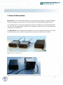
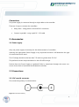
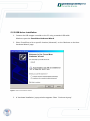
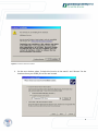
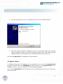
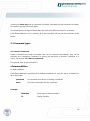
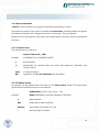
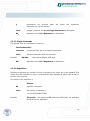
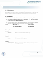
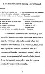
User Manual MC-101-01 Controller and Driver for 2 Phase Stepper motors Stand-alone or network-compatible 1 Content 1 General Information 4 2 Accessories 5 2.1 Power Supply 5 2.2 Connections 5 2.2.1 DC coaxial connector 5 2.2.2 Motor Connections 6 2.3 PC Communication 6 2.3.1 Configuration 6 2.3.2 USB Driver Installation 7 2.4 Hyper Terminal 3 Features 9 10 3.1 Multiple Axis Control 10 3.2 Joystick operation 10 3.3 Front Panel Button 11 3.4 Macro 11 3.5 Single / Multiple Commands 11 4 Commands 4.1 Command Types 11 12 4.1.1 Special Command 12 4.1.2 Instant Commands 13 4.1.3 Macro Commands 13 2 4.1.3.1 General Form 13 4.1.3.2 Define Macro 13 4.1.3.3 Single Commands 14 4.1.3.4 Repetitions 14 4.1.3.5 Saved Macros 15 4.1.3.6 Limitations 15 4.2 Examples 15 4.3 Commands description 146 3 1 General information MC-101-01 is a is a miniaturized single axis controller/driver providing in a single package a complete standalone control system for a wide range of 2-phase bipolar stepper motors. It is typically used in ultra-precise positioning systems for laboratory and industrial applications and with the appropriate mechanics it is capable to deliver sub micron precision and velocities up to 300 mm · sec-1. The MC-101-01 can be operated as standalone or it can be networked with up to 6 other controllers using only one power supply and interconnection cables as shown below. Figure 1: Front fiew of the MC-101-01. Figure 2: Back fiew and connection of two MC-101-01, only one power spply is neccessary. 4 Connections The power supply is connected through a single cable to the controller. There are 2 ways to connect the controllers: Daisy-chain - using phone cords with RJ11 connectors Connect in parallel – using a split RS – 232 cable 2. Accessories 2.1 Power supply Only one power supply is necessary for the whole network of controllers. Selecting the appropriate Power Supply is very important because it will determine the type of motors that can be used. The PS voltage should not be less than 7.5V and not greater than 35 V DC. The preferred current output should be in the 0.5A till 3A range. Derived from the Power Supply a regulated 5Volts is transmitted through the motor connector for the limit of travel and the deceleration switches. 2.2 Connections 2.2.1 DC coaxial connector The connection polarity it is shown below: Figure 3: Connection Polarity. 5 2.2.2 Motor connections Motor connections for the multi pin connector 10 on the front panel: Pin 1 Pin 2 Pin 3 Pin 4 Pin5 Pin 6 Pin 7 Pin 8 Pin 9 Pin 10 Index (Reference) VCC (+5 V DC) Encoder Ch A Encoder Ch B GND Limit (optional) Phase B Phase B + Phase A – Phase B + 2.3 PC communication 2.3.1 Configuration The controllers delivered with RS-232 interface do not require a driver to operate. The default configuration as delivered from the factory is shown below: Speed - 9600 bits/sec Data Bits -8 Parity - None Stop Bits -1 Flow Control - None The same configuration is used for serial and USB communications. The difference between them it is the physical layout. When using the controller with a USB interface a USB driver is provided. 6 2.3.2 USB driver installation 1. Connect the USB stepper controller to the PC using a standard USB cable. Windows opens the Found New Hardware Wizard. 2. Select “Install from a list or specific location (Advanced)” on the “Welcome to the New Hardware Wizard” page. Figure 4: Found new hardware window. 3. A “Hardware Installation” popup window appears. Select “Continue Anyway”. 7 Figure 5: Hardware installation window. 4. On the next window, select “Include this location in the search” and “Browse” for the location where your USBX_Driver files are located. 8 5. Click the Finish button on the “Completing the Found New Hardware Wizard”. 6. Open the “System Properties” dialog box and on the “Hardware” page, and select the “Device Manager” button. The Device Manager window opens. The newly installed USBXpress Device should appear in the “Universal Serial Bus Controllers” list. See section 4.Quick Start to establish the communication. 2.4 Hyper Terminal To illustrate the power and simplicity of the commands, you can use the HyperTerminal program included with most WINDOWS operating systems. If the HyperTerminal is not available on your PC you can download it or any terminal programm. See section 4 Commands of this document for a list and description on how to use the two letter commands. 9 3 Features 3.1 Multiple axis control The MC-101-01 allows the connection of up to 7 controllers to a single RS-232 channel. This capability can save cabling and power supplies in larger systems, and requires a single communications port for all eight axes of control. See figure 2 for the connection. 3.2 Joystick operation (with configurable digital display ) Figure 8: Configuration with joystick. One or 2 axis can be controlled as shown above from a simple Joystick console (sold separately). Only one power supply and no PC is required to operate. Available controls are position, velocity and acquiring home reference. 10 3.3 Front Panel Button The front panel button toggles the execution of Macro 1 (CM1) and Macro 2 (CM2). Pressing the button first time starts the execution of Macro1. Pressing it again executes Macro 2 and so on. 3.4 Macro 0 At startup, the controller automatically executes Macro 0 (CM0). The user can write his own startup sequence and store it in Macro 0. If the user doesn’t need anything to be executed at startup, then Macro 0 can be defined differently. For example: DM0=TP (Tell Position command). 3.5 Single/multiple commands The MC-101-01 controller uses 2-letter commands to allow it to perform multiple functions. The commands can be executed instantly, repeated multiple times or saved. See details in section 4.Commands of this manual. 4 Commands Commands are used to interact with the motor-controller system. They can be issued from a PC using the Hyper Terminal program. Refer to the 2.3 PC Communication section. All the commands have the basic format of 2 characters that may or may not be followed by a number. Multiple commands can be issued and/or stored in a single string, each single command being separated by comma. The maximum length of a string is limited to 94 characters, including spaces and blanks. Commands are not case sensitive. Capital and lower case letters are interpreted the same way. 11 Pressing the Enter Key after a command is finished, will repeat the last command or Macro. No need to type the command again. The Board Address is required when there are more controllers connected in a network. If the Board Address is 0 or is missing, all of the controllers will execute the command or the Macro. 4.1 Command types 4.1.1 Instant commands Instant commands are single commands that can be executed immediately. They can be executed as a standalone command or during the execution of another command or a macro. See section 4.1.2 Macro Commands. The general form of the command is: aCommandValue a = Board Address If NO Board Address is specified OR if the Board Address is 0, then the macro is loaded into all of the boards Command = a command from the list of existing commands Value = the value associated with the command Example: 2MA1000 1000 steps for board number 2 TP Display Position. 12 4.1.2 Macro commands A Macro is one command or a group of commands separated by comma. The maximum length of the macro is limited to 94 characters, including blanks and spaces. The blanks and spaces don’t change the content of the macro. They are ignored. Macros are not case sensitive. This means that capital letters and lower cases are interpreted the same. 4.1.3.1 General Form The general form of a macro is: a(Cmd1,Cmd2,Cmd3,…)RPm Example: 4(MR20000, TP,mr-1000RP20, tp)RP6 a Board Address () parentheses are required when the macro has repetitions. Otherwise they can be omitted Cmdn RPm a single command. repetitions. See 4.1.3.4 Repetitions for description 4.1.3.2 Define macro An exception to the general form of a macro is the define macro format. This macro has a special format because we save it in the memory. aDMNumber=(Cmd1, Cmd2, Cmd3,…) RPm Example: 4DM3=(MR20000, tp,wa, MR-1000rp20, TP)RP1000 a Board Address DM Define Macro label command Number the Number of the Macro (0 to 8) = the Equal sign is required 13 () parentheses are required when Otherwise they can be omitted. the macro has repetitions. Cmdn a single command. See 4.1.3.3.Single Commands for description RPm repetitions. See 4.1.3.4 Repetitions for description 4.1.3.3 Single Commands The general form of a command in a macro is: CommandValueRPm command a command from the list of existing commands Value the value associated with the command Example: MR4000 RPm means Move Relative 4000 steps repetitions. See 4.1.3.4 Repetitions for description 4.1.3.4 Repetitions Repetitions represent the number of times a command or a macro has to be repeated. That means that the command or macro is executed and then repeated as many times as the repetition value specifies. The format of the repetition is: RPValue RP repetition command Value the number of repetitions. 1 to 9223372036854775807 Example: (TP)rp1000 will execute the TP Command 1001 times, the parentesis are neccessary for repetitions 14 4.1.3.5 Saved macros Macros saved in the memory have a macro number. Each time a macro is called from the memory, it needs to have its number specified. The number oft the macro can be 0 to 8. 4.1.3.6 Limitations 1. The maximum length of the Macro is limited to 94 characters, including blanks. 2. The maximum number of Macros saved in the memory is 9. This means there is available space to save Macro 0 to Macro 8. 3. You cannot call an existing Macro (already saved in the memory) when you define a new Macro. However you can call a saved Macro for execution or display. Example: DM5=(CM2,…) is not accepted 4(TP, CM2, TM4, EM5,…) is a valid Macro 4.2 Examples Example 1 4MR6000 Board 4, execute Move Relative 6000 steps Example 2 sv1200 Set Velocity to 1200 for any board Example 3 (4MR6000)RP24 Board 4, execute Move Relative 6000 steps and repeat the movement 24 more times 15 Example 4 2SV2000,tp,(mr3000)rp1,TP Board 2, Set Velocity to 2000, display (Tell) Position, Move Relative 3000 and repeat the movement 1 more time, Tell Position Example 5 6(TP,mr1000RP2,SV1200,MR-3000,WA300)RP20 Board 6, Move Relative 1000 and repeat 2 more times, Set Velocity to 1200, Move Relative –3000, Wait 300 milliseconds, and repeat the whole Macro 20 more times. Example 6 4DM2=(MR44000,tp,mr-44000)RP8 Define Macro 2 for Board Number 4. The Macro (MR44000,tp,mr44000)RP8 is saved in the memory Example 7 (TP, TM2, CM2, SV2000, MR-50000,CM4)rp100 Display Position, Display Macro number 2, Execute Macro number 2, Set Velocity to 2000, Move Relative –50000 steps,Execute Macro number 4 and repeat the whole macro 100 times 4.3 Commands description To simplify the description, the board address will be omitted, but it is required for all the controllers with a board number different than number 0 when they are connected in a network. If the value of a command (which requires a value) is missing, than the default value of 0 is assigned to that command. 16 ma300comm MN and MF function description notes motor on motor off MA move absolute MA123456 move an absolute number of steps from home MR move relative MR123456 move relative from current position AB abort motion abort the movement or macro in execution ST stop movement stops movement only, a macro will got to next command DH define home define any position as home GH go home moves to the home position WA wait [ms] SA set acceleration WA1000 stop execution for 1s tp 1 … 10’000 higher acceleration can make to motor slip SV set velocity SM set micro stepping 1000 … 180’000 very high velocity can make the motor slip t UD saves new settings saves specific settings like SA,SV etc. settings are available after on/off FD factory defaults revert settings to factory default RPx repeat repeat the command or macro x times, parenthesis for command or macro are necessary SB RR1234 set baud rate reboot controller reporting commands RN reporting on RF reporting off TP tell current position GA get acceleration get stored acceleration GV get velocity get stored velocity GM get micro stepping get stored micro stepping macro programming (maximum length 94 characters) DMx define macro DM1=(MA123456,WA2000,GH,WA3000) TMx tell macro TM1 EMx erase macro EM1 CMx command macro CM1 executes the macro x 17