1
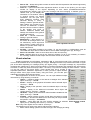
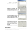
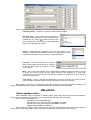
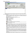
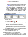
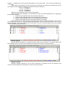
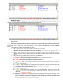
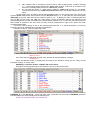
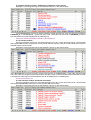
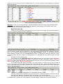
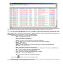
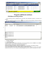
Security Commander for Windows 4.3.xx User manual. Table of contents. Security Commander for Windows............................................................................................................1 Table of contents.......................................................................................................................................2 General information...................................................................................................................................3 Installing and launching the program........................................................................................................3 Interface....................................................................................................................................................3 Object window. .....................................................................................................................................5 Event window. ......................................................................................................................................6 Information toolbar.................................................................................................................................7 Status panel. .........................................................................................................................................7 Control panel. .......................................................................................................................................8 Program main menu. ............................................................................................................................8 File submenu.....................................................................................................................................8 Utilities submenu................................................................................................................................8 Archive submenu...............................................................................................................................9 Service submenu...............................................................................................................................9 About submenu................................................................................................................................10 “Alarm list” information window. ..........................................................................................................10 “Alarm” window. ..................................................................................................................................10 Program general settings........................................................................................................................11 System settings. .................................................................................................................................11 Receiver settings. ...............................................................................................................................13 DB editors...............................................................................................................................................14 Object database editor. .......................................................................................................................14 Header and the first tab....................................................................................................................15 Details tab........................................................................................................................................17 Zones tab.........................................................................................................................................17 Events tab........................................................................................................................................20 Work Schedule tab...........................................................................................................................25 Hardware tab...................................................................................................................................26 Notes tab..........................................................................................................................................26 User database editor...........................................................................................................................26 Receiver system events editor.............................................................................................................27 Working with archive...............................................................................................................................28 Working with CU4000 central unit .log file...............................................................................................31 Program additional windows...................................................................................................................33 RP4000dm monitoring window............................................................................................................33 ComRP window...................................................................................................................................34 2 General information. Security Commander for Windows – software, designed to organize workplace of the security signalization system operator. Software works under Windows 9x/2000/XP OS and provides following functions: - processing of the messages that simultaneously come from several central stations (up to 15); - received information visualization; - message tracking (signal level, retranslation routes, etc.); - adjustable program interface; - language selection; - visual display of object status information; - received information and operator actions archiving; - vide options using databases and archives; - periodical control of database status; - periodical database backup; - database encrypting using double password; - fast and easy access to any object information; - possibility to add an image to object card; - possibility to create default object configuration library; - possibility to receive and control object telemetry information; - general and additional work schedule for every object; - efficient control of not restored alarms; - periodical reminding of not restored alarms; - automatic control of transmitters’ and security panels’ test messages; - report generating and printing; - object search using specified parameters; - object sorting, using status, group, class and event type; - possibility to send messages to client’s E-Mail, mobile phone, pager; - three levels of access to program options; - receiver system functioning control; - time synchronization between PC and receivers; - control of communication with receivers; - GSM-modem support and possibility to receive messages from GSM-transmitters; Current manual is made to acquaint user with basic principles of software use. Installing and launching the program. To install the program, launch Setup.exe file from the installation CD and follow the instructions. After installing the program, launch it using WSC icon in Start menu. You’ll have to enter user Login and Password. After installation only one user is registered in the program - Administrator, who has full access to all program functions. Login – sys, Password – sys. Administrator Login is fixed and cannot be changed, but it's strictly recommended to change the password. Interface. Program interface has a large amount of adjustable parameters that allow every user to reach maximum work comfort. Interface structure consists of general “Monitoring” window and few secondary windows. General window is shown on Pic.1. 1 2 3 4 5 6 Pic.1. General “Monitoring” window. 123456- Program general window. Control panel. Event window. Information toolbar. Object window. Status panel In this window you can see all operative information about objects and system status information. You can also control all program functions and open general services. Object window. This window is made in a shape of a table that contains all information about objects registered in DB opened for monitoring. For better visualization, objects in the table are shown in different colors, depending on the type of the last message. Black color means that there were information messages since object registration or it’s last editing. Objects removed from monitoring are shown in gray color. Window has a number of parameters that can be adjusted by user. Parameter adjustment is made through context menu (right mouse button). Using this menu, you can also open additional information about selected object, open object editor and search objects in the table. Menu appearance is shown on the picture. You can open additional object information by using following commands: • History – operative display of the last ten messages from selected object. «Hot key» – Ctrl+H. • Picture – display of the graphical information about selected object. «Hot key» – Ctrl+P. • Notes – display of the operator’s notes for selected object. «Hot key» – Ctrl+T. • Details – display of the advanced information about object and contact persons. «Hot key» – Ctrl+D. • Hardware – display of the information about hardware installed on the object. «Hot key» – Ctrl+A. • Problem – allows operator to leave a note about a problem occurred on the object. All notes are added to list, where they can be processed and printed. «Hot key» – Ctrl+Alt+В. • Archive – opens filter that can form archive selection for selected object (see p. «Working with archive»). «Hot key» – Ctrl+В. Note. Only Latin register can be used for «Hot keys». The following menu options are used to adjust window interface: • Visible fields – determines fields that will be shown in the table. To show the field, you have to select it in the list that appears when selecting this option. The following fields are available for display in the table: Object window - Nr – object number in DB. context menu - Test time – expected time, when transmitter test message should be received. - ID – source of the last message: receiver number/slot (line) number/device address. - Name – object name. - Description – object short description. - Date/Time – time, when last message was received. - Status – object status (armed/disarmed). - Event type – type of the last received message. - LV – object radio signal level. - Last message – last object message. - HI – physical address of the last repeater that transmitted message. - HN – number of times, message was repeated. - TG – type of transmitted data. - tTim - expected time, when security panel test message should be received. - TxAdr – address of the transmitter installed on the object: receiver number/slot number/address. - Account – number of the panel installed on the object: receiver number/line number/number. - GSMPhn – GSM transmitter phone number. - Adr – object address specified in the «Address» field of the Details tab in the object card. Note. Field order in the table by default is set same as in Visible fields option. To change it you have to move cursor to the field header and by pressing and holding left mouse button move column to the preferred place. To adjust field width place cursor on the right header border and after “<||>” symbol appears, adjust width by pressing and holding left mouse button. • Font – allows setting optimum font size and type, and changing encoding. • Freeze – freezes all fields to the left of the selected. Freezed fields will be fixed when table is scrolled. • UnFreeze – cancels previous command. • Editor – opens object editor. «Hot Key» – Ctrl+E. • Search – allows searching in the table using additional menu fields. In the Nr field search is made using object numbers, in other fields – using any record fragment. Search is started from the first record. • • • • • • • Save to file – allows saving table content as text file with field separation with tab and opportunity to import it into MS Excel. Filter On – opens information filter adjustment window. As seen on the picture, you can adjust window for display of the objects depending on their status (armed/disarmed/24hour arming/unknown status), type of the last message and their belonging to defined groups or classes. Also you can display this information in new window, leaving in general window not filtered information. You can open up to three additional windows (with individual filtering in each). If filtering is made in general window, field headers are marked out by red color. If in additional – in status panel are shown number of objects in the window and types of filtration. Additional window field settings are identical to the general window field settings. Filter off – Cancels information filtering in general window. Maintenance – when object is in this mode, all messages from it are not followed by sound signal and Filter adjustment window alarm window. Usually used not to distract an operator when object is under maintenance. Set Msg – send SMS message to the object. To use this function, a GSM-modem must be connected and object device must be able to receive SMS messages (RT4-5gc, RT4-5gs). Service is executed – starts a count-down timer to the next servicing. Show –displays object on a map in the „Tracking” software. To do so, it’s necessary to create in the „Tracking” software a static object with the same number as in WinSC. Event window. Displays messages from all objects, registered in DB, in chronological order. Every message is shown in one row and marked out in color depending on it’s type. Messages that are not processed are shown in upper part of the table depending on message priority (the higher priority – the higher message is). Unprocessed messages are marked out by “Bold” font and underline. Processed messages and messages with equal priority are shown in order they were received (the later – the lower). To process a message in alarm window – choose it in the list, select it and press “Enter”. Event window also has a number of adjustable parameters. Parameter adjustment is made, just like in object window, through context menu (right mouse button). Using this menu, you can also open additional information about selected object. Menu appearance is shown on the picture. You can open additional object information by using following commands: • History – operative display of the last ten messages from selected object. «Hot key» – Ctrl+H. • Picture – display of the graphical information about selected object. «Hot key» – Ctrl+P. • Notes – display of the operator’s notes for selected object. «Hot key» – Ctrl+T. • Details – display of the advanced information about object and contact persons. «Hot key» – Ctrl+D. • Hardware – display of the information about hardware installed on the object. «Hot key» – Ctrl+A. • Problem – allows operator to leave a note about a problem occurred on the object. All notes are added to list, where they can be processed and printed. «Hot key» – Ctrl+Alt+В. • Archive – opens filter that can form archive selection for selected Event window context menu object (see p. «Working with archive»). «Hot key» – Ctrl+В. Note. Only Latin register can be used for «Hot keys». The following menu options are used to adjust window interface: • Font – allows setting optimum font size and type, and changing encoding. • Visible fields – determines fields that will be shown in the table. To show the field, you have to select it in the list that appears when selecting this option. The following fields are available for display in the table: - S – Current message status. There are four statuses: 1. automatically processed 2. processed by operator 3. not processed 4. delayed - Date/Time – time, when message was received. - Event type – type of received message. - Nr – object number in DB. - Status – object status (armed/disarmed). - Message – message text. - ID – message source: receiver number/slot (line) number/transmitter address (security panel account). - Slot –slot (line) number of the receiver that received message. - RNum – number of transmitter that have sent message. - Name – Object name. - Adr - object address specified in the «Address» field of the Details tab in the object card. Also there are command to open object editor: • Editor – opens object editor. «Hot Key» – Ctrl+E. • Not sensual – when object is in this mode, all messages from it are ignored for specified period of time. • Maintenance – when object is in this mode, all messages from it are not followed by sound signal and alarm window. Usually used not to distract an operator when object is under maintenance. • Show – displays object on a map in the „Tracking” software. To do so, it’s necessary to create in the „Tracking” software a static object with the same number as in WinSC. Information toolbar. Information toolbar has a number of buttons to open additional information about selected object. Object can be selected both in object window and in event window. Button functions are completely identical to the similar options in context menu. Also this toolbar has “search”, “editor” and “cursor control” buttons. Status panel. Status panel has information about current date, disk space (less than 100 Mb are shown in red color) and receiver current status. In each time moment are shown status of only one of connected receivers, whose number is shown on the panel (#N, where N – receiver number). Status panel To select receiver you want to learn about you have to: - point mouse cursor on receiver number - one left mouse button click - select necessary receiver from the list Every receiver status consists of slot (line) status, power status and communication status. Information is shown in a following way: - Slot (line) status is displayed by color: - black – slot not installed (not used for lines) - green – slot (line) is functional - blinking green – slot programmed incorrectly or stopped (not used for lines) - blinking red – slot receiver or line failed. - backup battery status, / - no backup battery / - battery supply voltage low - battery supply voltage ok / - battery supply voltage too high - power supply status, - black – power supply ok / - blinking red – power supply failed - communication status. - black – communication ok / - blinking red – communication failed Control panel. Control panel. Control panel has following indication and control elements (from left to right): - unprocessed message counter - unprocessed message indicator - button to open program for .log file review (see «working with .log-file...») - button to open not restored alarms list (see ««Alarm List» information window») - current operator name - button to end current operator work session - help button - current time Program main menu. Program main menu («Hot key» – Alt) is designed to make basic settings and control general program functions. Main menu consists of the following submenus: - File - Utilities - Archive - Service - About File submenu. Consists of two items: • End session. Has the same function as button on the control panel – initializes end of current operator work session. • Exit. Exit program. Utilities submenu. Consists of the items to work with object users (operators) databases: • Users – has following functions for specified users work with DB: User DB Editor – opens user DB editor (see «DB editors») Operator Access Manager Access Supervisor Access – opens access level adjustment window. Administrator access level has full access to all program functions. Access adjustment window has following fields: 1.Exit – ability to quit program 2.Archive view – ability to view archive 3.Archive print – ability to print archive 4.Object edit – ability to edit object DB 5.Rec. settings – ability to configure receiver ports 6.Options – ability to configure parameters in “Options” menu 7.Cursor setting – ability to configure “cursor jumping” mode for object window 8.Operator configure – ability to configure operator access level 9.Manager configure – ability to configure manager access level 10. Supervisor configure – ability to configure supervisor access level 11. Windows config – ability to configure window parameters 12. Max. on alarm – allows to maximize program window, when message is received, if it was minimized 13. Save to file – ability to use “save to file” command 14. Utilities – ability to use program functions in Utilities menu. For every function are possible three access levels: 1. No – function not allowed 2. Yes – function allowed 3. R/O – function allowed in ReadOnly mode • • DB Repairing – initializes search and repair of errors in the DB. Repairing schedule – allows to set automatic periodical launch of DB Repairing function. You can set the following parameters: Period (days) – sets a time period of automatic DB Repairing function executing. Time – DB Repairing function executing time. Renewal of structure checkbox determines, whether information in object table will be updated after DB repair, or not. Reload channels checkbox, determines, whether connection with receivers will be reinitialized after DB repair, or not. • • DB Backup – initializes backup of DB data. Backuping schedule – allows setting automatic periodical launch of Backup function and setting backup directory. You can set the following parameters: Path – determines the path to the folder, where the DB backup copy will be saved. Period (days) - – sets a time period of automatic DB Backup function executing. Time – DB Backup function executing time. Reload channels checkbox, determines, whether connection with receivers will be reinitialized after DB backup, or not.. • Change system password – allows to administrator password (default - “sys”). It is recommended to change administrator password right after installing the program, because it is also used for data encryption. Archive submenu. Consists of the items to form archive extractions using given parameters: • Sort by Numbers – opens filter window to form archive extraction using object numbers in DB. • Sort by Tx Address – opens filter window to form archive extraction using object’s transmitter address. • Sort by Accounts – opens filter window to form archive extraction using object’s security panel. Note 1. Forming archive extraction for all objects, you can use any of these functions. Note 2. For additional information about archive extractions forming, see «Working with archive». • Sort by Status – Opens additional window with the list of objects that has specified status (armed/disarmed). For additional information see «Working with archive». Service submenu. Consists of the items to configure program general functions. • User info – displays information about current user: name, login and access level. It’s not possible to change parameters in this window. • Refresh – refreshes object window information. • Cursor Jump – controls “cursor placement on object” function. There are three modes: None – cursor isn't placed on an object On Alarm – cursor is placed on an object if alarm message received from it All Events – cursor is placed on an object if any message, followed by sound signal, received from it. • Receivers Settings – opens window for receiver channels parameters configuration. For more information see «Receiver settings». • Options – opens window for program general parameters configuration. For more information see «System settings». • System events Editor – opens receiver system messages editor. For more information see «DB editors». • Sound Off – turns off sound signal, that is started, when alarm message is received. • Not sensual list – list of objects and zones that was marked as Not sensual • Problems list – list of all problem notes made by operator. About submenu. Contains information about program version, and selected CU4000s serial number and software version. “Alarm list” information window. Can be opened by pressing appropriate button on the control panel and contains a list of all alarm messages that wasn’t restored. Also, in adjusted for every object period of time (Reminder timeout in DB editor), alarm windows for each message are opened. Repeated message is shown with R: symbol before message description. All messages can be sorted by number or by event type. If needed, messages can be deleted by pressing button. You can also add and remove information fields, change their size and order and choose font. Settings menu is opened with right mouse button. Note. To add alarm message to “Alarm list” window, in DB editor in “R” field add “Y” and set Reminder timeout value as zero. “Alarm” window. “Alarm” window is information window, but it has few special features that should be reviewed additionally. Window appearance is shown on the picture. 1 2 3 4 5 6 “Alarm” window initializes automatically, when alarm message is received. This window is always active and placed in front of the others program windows. “Alarm” window initialization is always followed by sound signal. Alarm window consists of the following components: 1. «Header» - contains information about an object that sent an alarm message. 1. First row – object number in DB and information source ID (transmitter address, panel account etc.); 2. Second row – event type, object status, date and time; 3. Third row – object name (see «DB Editors»); 4. Fourth row – object description (see «DB Editors»). 2. Event description – contains short description of event on the object (see «DB Editors»). In case if window initializes from not restored alarms (reminder) R: symbol is added to the event description. If received message is the same as received earlier - d: symbol. 3. Information panel. Contains buttons to open general information about object and contact persons. 4. Information. Displays information, selected by corresponding button on the Information Panel. 5. Operator comments. Allows operator to leave a comment about event, his actions, operative group actions etc. You can also use default comments (see «Program Main Menu). Comment list opens with F2 key. To add comment without opening a list, press Ctrl+comment number. For every event operator can add few commentaries by pressing Wait button after adding each one. In this case alarm window is closed and message in Event Window is marked by symbol. To add next comment you must do double click on this window and Alarm window will open again. After adding last comment press «Ок». After that, message is processed and placed into archive with all of the comments. For every comment in archive is added time when it was created. 6. Control panel. First three buttons (History, Hardware, Picture) allow to receive additional information about object that sent this message (see «Object Window»). Sound Off button allows turning off sound signal without closing Alarm window («Hot key» - F5). Wait button allows delaying final message processing until additional comments are added. Show button allows displaying object on a map in the „Tracking” software. Ok button processes message («Hot key» - F12). In case if next message is received before previous is processed, in event window is formed unprocessed messages queue. Those messages are placed in the upper part of the table according to priority (the hither the priority, the higher message is placed). Unprocessed messages are marked out by bold font and underline. Messages with the same priority are placed according to the time they were received. After processing, all messages are placed according the time they were received. Several alarm windows can be opened at one time. When sound signal is turned off, it is turned off for all unprocessed messages. But if there is at least one unprocessed message in the queue, reminder sound signal «ding» is on. Signal period is set in «Options» submenu. If after turning off the sound, a new message is received, sound is turned on again. If a message with a higher priority is received, than sound signal is changed to the sound, assigned for this new message. Note. Message priority is determined by its type (see «DB editors») Program general settings. System settings. System settings window can be opened through main menu in the program general window: Service\Options. Due to the fact that many of the settings affect program functionality, it is recommended that they would be configured only by qualified personnel. System settings window consists of 9 tabs, which will be observed below. Time. This tab is designed to adjust time synchronization between PC and CU4000s Central Unit. You can choose synchronization source (Source of synchronization) and it’s period. By default it is set to synchronize from PC with a 1 hour period. In the example, shown on the picture synchronization is made from PC with 10 minute period. Sound. In this tab you can adjust the following parameters: - - - Sound device – selection of the device, that will play the sound signals. It can be sound card or PC speaker. Also sound can be completely turned off. Sound repetition – determines a number of times, the sound signal will be repeated, when alarm window will appear. If the value is set to 0, than it will be repeated until it’s turned off by the operator. Alarm reminding – determines, how long it will take to form a reminder signal, if there are unprocessed messages. Timeouts. In this tab you can set a period of time, during which all identical messages from one object are considered one message (in case they are received in a row), and a program reaction when receiving a duplicate message. Mentioned period is set independently for zones (transmitter inputs) and events. If a checkbox To ignore duplicate messages, is active, than program will consider any duplicate messages received in a determined period of (Deaf time field), as one message. Program reaction can be the following: - None – duplicated message isn’t shown in event window. - Alarms – only alarms are shown. - All – all programmed events are shown. In case if the message is duplicated, it’s marked with “d:” symbol. Picture. Determines program, which will be used to open graphical attachments. Signals. Allows setting a unique sound signal for every type of event. To set a sound just select an appropriate .WAV-file. This file can be located either in the Sounds folder or in any other place of the hard drive. This option is only available is a sound card is set as a sound device. Comments. This is a list of standard comments, used by operator, when processing events in the alarm window. To edit a comment just double click it in the list. Groups. Allows creating and renaming groups, where you can later assign objects (see “DB editors”). Number of groups is not limited. When deleting a group and creating a new one on it’s place, all the objects that where assigned to the deleted group will automatically be assigned to the new one. Classes. Allows creating and renaming object categories (see “DB editors”). Number of categories is not limited. When deleting a category and creating a new one on it’s place, all the objects that where assigned to the deleted category will automatically be assigned to the new one. On air alarm. Allows tracking transmitters that transmit information too often, due to the connected devices malfunctioning. To do so a time period is set (T0(mm:ss)), and a number of messages that can be sent during this period (Count). If a number of messages exceeds adjusted number - the alarm message is generated. Message looks like this: Transmitter X/Y/ZZZZ on air, where Х – channel number, Y – slot number, ZZZZ – transmitter number. Receiver settings. Receiver settings window can be opened through main menu in the program general window: Service\ Receivers_Settings. Due to the fact that many of the settings affect program functionality, it is recommended that they would be configured only by qualified personnel. Receiver settings window appearance is shown on the picture below: When configuring receiving channel you can set the following parameters: - Channel number – Number of a channel. Used to identify objects. - Receiver Type – type of the receiver assigned for this channel. Receiver type can be chosen from the pulldown list by clicking symbol. Content of the list is determined by the presence of the appropriate drivers in the program main folder. - Source – determines the information source for the program. It can either be a COM port with attached receiver or log-file that is created by the similar program on any computer on the local network. - Filename – name and location of the log-file that is used to gather information from. Change of the file name, when it’s required is made automatically. - Map – map of the signal transfer. Sets correspondence between physical number of the slot or phone line (in the receiver) and it’s logical number (in the program). It is used when information from the object can be received from more than one slot (line), and you can only set one in the program. - Port setting – used to configure the COM-port to correctly work with the current receiver. Communication parameter values should be specified in the receiver manual. After pressing “OK” button, all configured parameters will be saved, chosen receivers are added to the system object database (if they weren’t added previously) and all used ports are reinitialized. DB editors. Object database editor. Object database editor is designed for creating object cards, filling them with appropriate information about object and signals, received from it, and for systemizing and saving this information. You can open object editor from: - Information panel, using Edit button - Context menu in the object window using Editor command - Context menu in the event window using Editor command - Keypad using Ctrl+E key combination. When opening an editor, it opens a card for the object that was selected in the object or event window. Object card consists of the heading and several tabs of information, grouped according to it’s type Header and the first tab. Object editor appearance is shown on the picture below: First tab is a list of objects (cards). Selecting an object will show it’s header. Header contains the following fields and buttons: - Object Nr - object sequence number in the DB. When you are creating a new object, you will automatically be advised to use the first unused number, but you can choose the next one or use any other. If the background is green – object is active, if red – removed from monitoring (see “Work Schedule tab”). - Name – Object name. Filled freely (max – 80 symbols). - Description – Object description. Filled freely (max – 80 symbols). - |< button – move to the first object. - < button – move to previous object. - > button – move to next object. - >| button – move to the last object. - + button – add object. - − button – delete object. - Х button – cancel changes. - - - button – convert all letters in the object card to capital letters. button – Copy object. When copying, data from the following tabs will be copied: Zones, Events, TLF Events and Work Schedules. button – save changes. button – allows attaching to the object card an image containing additional information about object or it’s location. Supported file formats - .gif, .bmp, .jpg, .jpeg, .emf, .wmf. There is a special folder named pict\ to store those files, but they can also be located anywhere on the hard drive. Transm. test time – time determining transmitter or repeater test message period. In case if during set period no test message was received from the device, an alarm message “No signal (TIME)”, is created, where (TIME) time during which there was no test message. If there were no signal for more than 3 days “No signal more then 3 days” message is created. It is recommended to set Transm. test time value a 5-10% longer than a real transmitter test period, to compensate possible timer deviation. If the value is set to 0 than test messages are not monitored. Object test time - time determining control panel test message period. Can only be used in RS4000 system using transmitter with communication interface (see RT4-5se user manual). If used in the “Events” tab must be entered an event with a S type (test). In case if during set period no test message was received from the device, an alarm message “No signal from object” is created. It is recommended to set Object Test time value a 5-10% longer than a real transmitter test period, to compensate possible timer deviation. If the value is set to 0 than test messages are not monitored. Reminder timeout – with this time period not restored alarm events from the “Alarm list” window will be repeated. Repeated messages are marked with R: symbol in the event description field - - - - (see “Alarm list” information window). If the value is set to 0 than alarm messages from this object won’t be repeated. Mail – allows sending an E-mail when an event occurred. This events are (see picture): 1. Object disarming at illegal time (see “Work Schedule”) 2. Object not armed (see “Work Schedule”) 3. No signal from object 4. No signal from transmitter In the Target/Address field are entered desired E-mail address; In the Target/Subject – message subject; In the lower field – message text. As you can see message can be sent to three different addresses. In the Reminder message field you can insert any important information and if Enabled checkbox is active, this information will be added to every sent message. Settings – opens an additional menu for choosing program reaction for different types of events. As you can see in the picture for every event type there are 4 checkboxes. Filled checkbox means that appropriate reaction is active, empty ignored. Corresponding reactions are shown on the top of the window: 1. Alarm – alarm window is initialized 2. Sound – appropriate sound signal is activated. If an alarm window is opened, than sound signal is played as many times as set in the Sound repetition field (see “System settings”). If no alarm window is initialized – than it is played only once. 3. Arch – event recording into archive. 4. List – event displaying in the Event window. For all types of alarm messages all this functions are always active. You can save the most recently used setting by pressing the SetAsDefault button. In the future you can load this setting by pressing Default button. This setting also is used when creating a new object in the database. Radio – list of identification parameters for the device that uses radio communication channels. Consists of 4 parameters: 1. Tx Address – physical device address 2. Channel – receiving channel number (receiver). See “Receiver settings”. 3. Slot – Slot number (receiving channel), from which information should be received. 4. Device type – allows choosing type of described device: transmitter (Tx) or repeater (Rx). Phone - list of identification parameters for the device that uses wire communication channels (phone lines). Consists of 3 parameters: 1. Account – control panel account or GSM-transmitter PIN-code. 2. Channel – receiving channel number (receiver). See “Receiver settings”. 3. Line – number of the line that is used to receive information. 4. In case if in the Line field was selected GSM parameter (is information is transmitted using GSM network), than the fourth field Phone will appear. There you have to specify phone number of the SIM-card that is inserted into a GSM transmitter (RT4-5gc). Phone number must be entered with the international code (+371xxxxxxxx, etc.). - Editor – menu that contains a list of functions to switch to general tabs and fields and appropriate hotkeys. Details tab. This tab is designed for more specific object description and to specify contact persons. Tab appearance is shown below. As you can see there are fields to specify object mail address, it’s informational address and to assign object to a group and category (see “System settings”). Also you can specify a key-word to identify client if he is calling to the central station. All this information can be seen by an operator when he presses the Details button in the alarm window or on the information panel in program main window. Zones tab. This tab is designed for describing signals from the inputs (zones) of transmitter, repeater or zone expander. It consists of the following fields. NR – object number. This is an information field and can’t be edited. P – can take 2 values: N – zone is monitored permanently, P – zone is monitored only if object status is Arm. It’s not recommended to often use this function, due to the possible loss of information. Zone – Zone number. Number of the transmitter’s described input. If you don’t use the zone, you don’t have to describe it. In case if there are an event on the undescribed zone, it is considered as an E – Event type and displayed in the following way: Unspecified zone switch: with a list of activated zones. T – event type. For every event, described in the 0-1 and 1-0 fields, you have to assign a type. Every type is marked with it’s own color, both in the editor and in the program information fields. This allows significantly ease operator’s information comprehension. There are the following event types: 1. P – Panic – alarm event. Received when a panic button is pushed on the object. 2. F – Fire - alarm event. Received when a fire alarm goes on. 3. B – Bur - alarm event. Received when burglary alarm goes on. 4. T – Trouble – alarm event. Describes different object malfunctions (tamper alarm, low battery, etc.) 5. A – Arm – Object arming. 6. D – Disarm - Object disarming. Those events are usually describe two states of one zone. Every described object can have only one zone with D or А event type. If object doesn’t have zones with these events, than it’s status will always be Arm. 7. R – Restore – Zone restore. Used to describe zone normal state for 1 – 4 event types. 8. E – Event – neutral event. To change event type use the „space” key or press corresponding letter key. Zone switch 0-1 and Zone switch 1-0 – Event descriptions. In each of these fields you have to describe an event for each of the zone states. So, in Zone switch 0-1 field you describe an event that corresponds zone switching from „closed” state to „open” and vice versa. If transmitter inputs are loaded to „+” or you use RS1000 transmitter, than descriptions for „closed” and „open” states are switched to opposite. For system events (“low battery” and “AC lost”) Zone switch 0-1 will always be alarm and Zone switch 1-0 – restore. If input number is added to the list, but no description is given, than information from this input is ignored. R – can take two values: Y – alarm event is added to “Alarm List” window, N – not added. This function will work only if Reminder timeout parameter in the window header has nonzero value. M –E-mail sending. Every event for every zone can be automatically sent by E-mail to the mobile phone, pager or other E-mail address. To open mail editor just right-click on the event description field and select Mail from the context menu. Mail editor window will open: In the Target/Address field you enter E-mail address; In the Target/Subject field – message subject; In the lower field – message text. When E-mail is sent, time, when event was received by CU is added to it. As you can see, you can send E-mail to three different addresses at a time. To save information just press button, to delete – . Events that will be mailed are marked with symbol in the M field. Mail sending is made by an additional program that is not included in the default software package. Described software version allows saving zone descriptions to the text file in the ZCard folder and load it to the object card in the future. This is made using context menu that contains following items: 1. Save to card – saves all described events in current object card to the text file. 2. Load from card – loads zone descriptions from selected text file. Any zone description that was entered before is deleted. 3. Append from card - loads zone descriptions from selected text file. Any zone description that was entered before will not be deleted. For every receiver type, zones have to be programmed differently. RT4-5p transmitter (RS1000 system). RT4-5p transmitter has fixed amount of zones – 5. User can freely assign first four of them, but the fifth zone controls state of the power supply (battery). Zone 5 state – 0 normal battery voltage, 1 – low battery voltage. States of the other zones are sent depending on transmitter work mode. Transmitter mode. In this mode zone „open” state is sent as 0, and „closed” – as 1. Control panel mode. In this mode „closed” state of the status zone is always Arm status and sent as 1. „Open” state of the status zone is always Disarm status and sent as 0. For other zones their alarm state (opened or closed) is determined by transmitter programming and sent as 1. Zone restores are sent as 0. RT4-5se transmitter (RS4000 system). If no interface modules are connected, than RT4-5se transmitter has 7 zones. User can freely assign first six of them, but the seventh zone controls state of the power supply (battery). Zone 7 state – 0 normal battery voltage, 1 – low battery voltage. Other zone state transmitting are determined by zone load. If zones are loaded to „+” (default) zone „open” state is transmitted as 1 and „closed” state – as 0. If zones are loaded to „0” – vice versa. When using zone expanders, the first and the second zones are not used and not programmed. Zones are assigned for the expander according to it’s address and are the following: - 9 to 16 – for address 0. - 17 to 24 – for address 1. - 25 to 32 – for address 2. - 33 to 40 – for address 3. Expander zone programming is the same as transmitter’s. When connecting one transmitter to a few objects it’s zones are divided between them. Programming process is the following: 1. Create an object with N number and transmitter address X. 2. Program object parameters and zones that assigned to this object. 3. Create an object with M number, but leave transmitter number as X. 4. Program object parameters and zones that assigned to object. M. This procedure can be made with every transmitter type. Number of objects assigned to one receiver is only limited by the amount of zones (including zone expanders). One zone cannot be used on two or more objects. Example of two objects assigned to one transmitter is shown in the picture below (zones that assigned to other transmitter are grey colored). RP1000 repeater. RP1000 repeater transmits to CU information about state of the two tampers, AC, backup battery and test messages (every 12 hours). Recommended zone assignment is shown on the picture below. RP4000s repeater. RP4000s repeater transmits to CU the same information as RP1000 but with the different zone numbers. Recommended zone assignment is shown on the picture below. RP4000d repeater. RP4000d repeater transmits to CU the same information as RP1000 but with the different zone numbers. Recommended zone assignment is shown on the picture below. Events tab. In this tab are described signals that are received from control panels. Event codes are read from the control panels using interface modules that are connected to the inputs 1 and 2 of the receiver. In that case, these inputs work as serial port. Event code transition is only possible using RT4-5se transmitter (RS4000 system). To describe an event the following fields are used: NR – object number. This is an information field and can’t be edited. Account – Contains information that allows to identify control panel. For different types of interface modules can have different structure (see below). Event – must contain an event code that is generated by control panel. For different types of interface modules can have different structure (see below) Code must be entered fully (including left 0’s). M – E-mail sending. Filled exactly the same as in the Zone tab. T – Event type. Possible event types are listed below: 1. P – Panic – alarm event. Received when a panic button is pushed on the object. 2. F – Fire - alarm event. Received when a fire alarm goes on. 3. B – Bur - alarm event. Received when burglary alarm goes on. 4. T – Trouble – alarm event. Describes different object malfunctions (tamper alarm, low battery, etc.) 5. A – Arm – object arming. 6. D – DArm - object disarming. As opposed to zone programming, when programming an event type there can be more than one event with A or D values for one object. 7. R – Restore – alarm restore (for types 1 – 4). 8. E – Event – neutral event. 9. S – Tst – Control panel test message. This is not an information event, but if it won’t be received in a time period that determined in Object test time field, a following event will be displayed: No signal from object! Message – designed for describing event that corresponds to the current event code. If this field is not filled, than event is ignored no matter what type it is. If a message is received that is not in the database than it will be displayed as an E – Event type. The way message will be displayed depends on the type of interface module. rEv – Restore code. In this field you have to enter a code, receiving which, an alarm message (1 – 4 event types) will be deleted from “Alarm List” window. If the code is not entered, you will have to manually delete event from “Alarm List” window. R – can take two values: Y – alarm event is added to “Alarm List” window, N – not added. This function will work only if Reminder timeout parameter in the window header has nonzero value. To ease object entry procedure and decrease database size you can change part of the event code symbols (Event field) and/or Control panel account (Account field) to „?”. In that case into event description (Message) are put any code that has any symbol in place of a „?”. To identify an event, in the description text are put „[E]” (for the code) and „[A]” (for control panel account) combination that will be replaced by the appropriate symbols from the event code (see example below). Number of „?” in the event code cannot be more than number of symbols in the event code, but they must be positioned from right to left, without any other symbols between them. If there are need to assign to one of the codes programmed with „?” a special description, you have to enter this code as an additional line (code 43 in the example). Example of using „?” when programming events: If an event with the code 41 is received, then operator will see the following message: Alarm in zone 1 If an event with the code 43 is received, then operator will see the following message: FIRE alarm !!! There are different issues in programming according to the interface module you are using, but the principles of using „?” are the same. PARADOX_2 interface module – ESPRIT 7X8 control panel. Example of event programming for this situation is shown on the picture below. In the Account field you have to specify interface module number from 00 to 03 (see user manual for PARADOX_2), in the Event field – group and event code. Code table can be found in PARADOX_2 manual. Not described event will be displayed in the following way: Group Of Event/Event=5001 Card number=02 IF_paradox interface module – SPECTRA, IF_Magellan control panels. Example of event programming for this situation is shown on the picture below. In the Account field you have to specify interface module number from 00 to 03 (see user manual for PARADOX_2), in the Event field – group and event code. Code table can be found in PARADOX_2 manual. Not described event will be displayed in the following way: Group Of Event/Event/Partition=0D0401 Card number=01 IF-1.2 interface module. Using this interface module you can read information from any control panel that has tlf. communicator and supports 4x2 impulse transmission format (see IF-1.2 user manual). Also all control panels that are part of RS4000 system use this format. Example of event programming for this situation is shown on the picture below.. In the Account field you have to specify control panel account, in the Event field – event code. Panel account and event codes are programmed in control panel manually. Table of recommended codes is attached to the IF1.2 interface module manual. Not described event will be displayed in the following way: Account=1234 Event=15 IF-1.4id interface module, RT4-5se/id transmitter. Using this interface module you can read information from any control panel that has tlf. communicator and supports Contact ID transmission format (see IF-1.4id user manual). Example of event programming for this situation is shown on the picture below. Account field has the following structure: AAAAGG Where G – partition number, A – panel account. There are no any additional symbols between partition number and panel account. If panel account is shorter than 4 symbols, than left zeroes may be discarded. Number of symbols in partition number must always be two. For example if panel account is 123 and partition number is 2, than you must enter the following in the Account field: 12302. Event field always consists of 7 symbols and has the following structure: MEEEZZZ. where М – modifier, Е – event code (see code table in the panel manual), Z – zone or user number (if the event doesn’t describe any zone or user actions, than you have to enter zeroes there). М modifier in the Event field may possess 2 values: М=1 if the event is alarm or disarming; М=3 if event is alarm restore, arming or information/service event. Not described event will be displayed in the following way: Event=1137001 Account=2345/01 TLF Events tab. In this tab are described signals that are received from control panels using wire line channel (phone line) or GSM channel. Program supports different kinds of alarm receivers (Central units), and this list expands all the time. Every central unit has it’s own message format that he transmits into the program. Also format may depend on the central unit individual settings. Considering the above it’s not suitable to describe event programming for every central unit, so this section will describe programming main principles and give some general advices. To describe an event the following fields are used: NR – object number. This is an information field and can’t be edited. Partition Nr – partition number. If the control panel has only one partition and used transmitting format doesn’t obligatory need partition number, than this field remains empty. Event code – must contain event code that is received from control panel. For different communication formats it can have different size and structure. M – M – E-mail sending. Filled exactly the same as in the Zone tab. T – Event type. Possible event types are listed below: 1. P – Panic – alarm event. Received when a panic button is pushed on the object. 2. F – Fire – alarm event. Received when a fire alarm goes on. 3. B – Bur – alarm event. Received when burglary alarm goes on. 4. T – Trouble – alarm event. Describes different object malfunctions (tamper alarm, low battery, etc.) 5. W – Pwr – 220V circuit control. Events of this type are acting the following way: when alarm is received, program acts according to settings, made for this event type in Settings window. If no restore is received for this event in a period, specified in the Reminder timeout field, than an alarm window will be opened again automatically. 6. A – Arm – object arming. 7. D – DArm – object disarming. As opposed to zone programming, when programming an event type there can be more than one event with A or D values for one object. 8. R – Restore – alarm restore (for types 1 – 5) 9. E – Event – neutral event. 10. S – Tst – Control panel test message. This is not an information event, but if it won’t be received in a time period that determined in Object test time field, a following event will be displayed: No signal from object! Message – Message – designed for describing event that corresponds to the current event code. If this field is not filled, than event is ignored no matter what type it is. If a message is received that is not in the database than it will be displayed as an E – Event type. The way message will be displayed in the following way: Partition= P EventCode= E , where P – partition, E – event code. Partition number may contain up to 3 HEX-numbers, event code up to 8 symbols. If partition number is not transmitted message will be displayed in the following way : Partition= EventCode= E. rEv – Restore code. In this field you have to enter a code, receiving which, an alarm message (1 – 5 event types) will be deleted from “Alarm List” window. If the code is not entered, you will have to manually delete event from “Alarm List” window. R – can take two values: Y – alarm event is added to “Alarm List” window, N – not added. This function will work only if Reminder timeout parameter in the window header has nonzero value. Same as describing events transmitted using radio channel, it is possible to change part of the symbols in the event code (Event field) and partition number (Partition Nr field) to „?”.In that case into event description (Message) are put any code that has any symbol in place of a „?”. To identify an event, in the description text are put „[E]” (for the code) and „[P]” (for partition number) combination that will be replaced by the appropriate symbols from the event code (see example below). Number of „?” in the event code cannot be more than number of symbols in the event code, but they must be positioned from right to left, without any other symbols between them. If there are need to assign to one of the codes programmed with „?” a special description, you have to enter this code as an additional line Example of using „?” when programming events for Sur-Gard MLR2-DG central unit (default format): As said above, event codes can have different structures. Usually communication formats and corresponding events are described in the central unit manual. To find out the structure of specific event from specific object it is recommended to use the following method: If you know the control panel account of the object, just create new object card and enter this account into the Account field in the header (see “Header and the first tab” section). After that, send a message from the object. You will receive an Event type message that is assigned to the object you just created. The message will have the following structure: Partition= P EventCode= E Now just fill the card, by entering received data into appropriate fields and when you will receive this message next time, you will see an event description of the appropriate type. If you don’t know panel account, then you don’t need to create an object card, but just send a message from the object. In that case you will also receive Event type message, but it will be assigned to central unit and will look the following way: Receiver:1 Line:0 Acc:115 Part:1 EvCode:C C4 As you can see this line contains full information to fill an object card. In the TLF Events tab Replace command works exactly the same as in the Events tab, but changes values in the Partition Nr field. RT4-5gc GSM-transmitter. RT4-5gc GSM-transmitter transmits information about it’s inputs, outputs and full information from connected control panel via SMS or GPRS-channel. For transmitter’s own messages, Partition Nr is always FF. In case if for event receiving is used GPRS-channel, than event code will contain two symbols (see picture below) Event code when using GPRS-channel In case if for event receiving is used CU-GSM central unit, you have to insert two zeroes between code symbols (see picture below) Event code when using CU-GSM Attention! In case if you are using RT4-5gc in GPRS transmitting mode, it is strongly recommended to enter both types of events (with and without zeroes in the middle) to avoid receiving not described events, if the GPRS-connection will be broken for some reason. Work Schedule tab. In this tab you can schedule disarming/arming for each object, and program will automatically trace it’s execution. Schedule example is shown in the picture. In the left column you specify days of the week. Then there are three Opening/Closing column groups, where you can set time of object arming or disarming. In first two column groups are the main schedule in the third spare. You can switch to spare schedule by activating Spare schedule checkbox. To stop object monitoring without deleting it’s object card, just clear Monitoring checkbox. In that case all messages received from this object are ignored and object number are highlighted red in the DB editor list (see “Header and the first tab” section). Schedule works the following way: Time interval set in the Opening/Closing fields, determines the time, when object may be disarmed. If at the time, specified in the Closing field, object is still disarmer, an alarm message is formed - Object not Armed !!! If object was armed properly, but was disarmed at the time, that is out of the specified range, another alarm message is formed - Disarm in illegal time !!! If you need to set a time interval, that starts on one day, but ends on another, than you have to break it in two. In the first day you set an interval that ends at 23:59, and at the other – interval that starts at 00:00. Any other intervals that have time difference less than two minutes are also considered as one interval. Example is shown in the picture below. In the picture, object can be disarmed from 19:00 Monday till 8:00 Tuesday. If the day is added into the schedule, but no time is set for it, it means that object must be armed all day. If the day is not added into the schedule than the schedule is not monitored this day. If an object has the same schedule for all days of the week, than you can simply enter the schedule for the Monday, open a context menu using right-click and select Copy. Schedule will be copied for all week. Hardware tab. This tab is designed to describe the hardware that is installed on the object. In the page header you enter type and manufacturer of the control panel and type of the trannsmitter and interface module (if installed). Lower there is a table, where you describe hardware that is connected to control panel and transmitter inputs. Table contains the following fields. - Nr – number of panel zone or transmitter input. - Cp_Tx – zone belonging to control panel – Cp or transmitter – Tx. - Name – Zone description - Sensors – sensor description. All fields are filled freely. This information can be requested by the operator, when pressing the Hardware button in alarm window or on the information panel in program general window. Notes tab. In this tab, you can enter any additional information about the object in plain-text. This information can be requested by the operator, when pressing the Notes button in alarm window or on the information panel in program general window. Size of entered text is not limited. User database editor. Due to the fact that you need an authorization to enter the program, you need to be able to assign a login and password for every user and determine their access permissions to the program functions. Full access has only administrator (login: sys – fixed). Administrator password (sys by default) can be changed using main menu Utilities/Change system password. Described editor is designed to create and edit user datebase. You can open editor using program main menu: Utilities/Users/User DB Editor. Window appearance is shown on the picture. To add a new user to the database you need to: - Press “+” symbol on the lower panel. Empty row will appear. - Enter login (5 symbols max) and real name of the user into log and Name fields. - Choose access category in the window right side – Operator/Manager/ Supervisor). - To enter password press Password button. Current password window will appear. If you are entering new password press „OK”, if changing already existing – enter it and press ”OK”. In the next windows you will have to enter new password and confirm it. To save changes press √. To cancel changes press Х. To delete user from the DB press “-“.To delete user you don’t need to know it’s password. To assign program functions, allowed for every access category, there are a access level editors. You can open them using main menu: Utilities/Users/Operator Access, Utilities/Users/Manager Access, Utilities/Users/Supervisor Access. Access level editor window is shown on the picture and are the same for all three access categories. The following functions can be edited: - Exit – ability to close the program Archive view – ability to view the archive Archive print – ability to print the archive Object edit – ability to edit object database Rec. settings – ability to configure ports for receiver connection Options – ability to configure parameters in Options menu Cursor setting – ability to configure cursor „jump” mode in object window Operator access – ability to configure operator access level Manager access – ability to configure manager access level Supervisor access – ability to configure supervisor access level Windows config – ability to configure program windows Max. on alarm – allows maximizing program window, when alarm is received (if it was minimized) Save to file – ability to use „Save to file” command Utilities – ability to use program functions in the Utilities menu For every function there are tree access levels: No – function not allowed Yes – function is fully allowed R/O – function allowed in read-only mode Receiver system events editor. System events are events that describe status of the receivers (central units) connected to the program. System event information is loaded into DB when you choose a receiver in the settings menu (see „Receiver settings”). Editor is designed only for it’s editing. You can open editor using main menu: Service/System events Editor. Editor interface is the same as object database editor, but only lacks parameters that are not used to describe receivers. Description of events from CU4000 and RR1000 central units is made in the Zones tab; other central units are described in the TLF Events tab. Event description rules are the same as for the object event description. On the pictures below are shown fragments of event description for CU4000 (radio) and MLR2-DG (tlf.) central units. CU4000 event description MLR2-DG event description Working with archive. All events, received from objects, operator actions and operator comments to processed events are saved in the archive. Archivated data is saved for all working period and can be sorted, displayed on the screen, saved to file and printed at any moment and for any time period. You can open archive filter window: - from the Archive option in main menu. - using context menu in the object or event windows (Archive command). In the first case you will see three submenus that determine general sorting parameter: - Sort by Number – allows sorting objects or object groups by their numbers in the DB. - Sort by Tx Address – allows sorting objects or object groups by the number of the transmitter, installed there. - Sort by Account – allows sorting objects or object groups by the account of the control panel, if information is delivered by wire line channels. If you open archive filter using context menu, than “Sort by Number” window will open. Number of object that was selected for context menu opening, will be automatically added to the sorting field. Appearance of all three windows is shown on the pictures below. “Sort by Number” window. “Sort by Tx Address” window. To receive information about repeaters, you have to add r prefix before the address. For example: r12 “Sort by Account” window. Note that an account number is in a HEX format. As you can see, these windows are differing only by object identification parameters that are used to filter the archive. All other selection criteria are the same and have the following purpose: - Date – allows defining the day period for the sorting. - Time – allows defining the time period for the sorting. If in the Date field are selected a period of more than one day, than sorting will be made from the “From” time of the first day, to the “To” time of the last. Whole day – if active, sorting is made for the whole day. - Event Type (1) – allows defining types of the operator actions and system events that will be used for sorting. - Event Type (2) – allows defining types of the object messages that will be used for sorting. - Operator – allows choosing only events processed by current operator. After all of the criteria is set, press “Ok” button. Time of the archive selection forming depends on the selected time period, amount of the requested information and computer performance and may take up to a few minutes. To stop archive selection forming, just press the Archive selection example is shown on the picture below. symbol in the upper right corner of the window. As you can see, window consists of header and information field. Information field content is formed from the events received by central unit and cannot be edited. Header is filled by user in free form. In the current program version there is a possibility to save archive selection into the text file, with opportunity to import it into MS Excel. To do so, you have to open context menu using right-click and select “Save to file” option. Also this context menu has a “Font” that allows choosing optimal font type and size, and “Visible fields” option that allows to remove not needed fields. Archive selection window can contain the following fields: - Date – message receiving date. - Time – message receiving time. - Nr – object number in the database. - Rnum – receiving channel number (see “Receiver settings”». - ID – message source: receiver number/slot (line) number/device address. - Name – object name. - Event type – event type. - Status – object status at the moment of receiving the message (Armed/Disarmed). - Message – event description. - Data – data block, received from the receiver. - HI – physical address oh the last repeater that the message went through (for CU4000 only). - HN – number of message repeats (for CU4000 only). - TG – data transmitting type (for CU4000 only). - Log – name of the operator that processed the message. - Slot type – slot type (for CU4000 only). - Slot – slot (line) number that received the message. Pressing the symbol will open report printing window. Report printing window appearance and it’s context menu is shown in the picture below. This window will have the fields defined in the archive selection window. In this window, there are following report forming functions: - Header font selection. Made using context menu by Header Font command. When selected, a standard font adjusting window will appear. There you can select font, font size, color, etc. - Text font selection. Made using context menu by Font command. All is similar to previous paragraph. - Field formatting is made by adjusting width for every column. To adjust column width you have to move cursor to the column border in the window header, left-click and hold mouse button and move it to the necessary position. To print the report, just press the button. Working with CU4000 central unit .log file. CU4000 central unit .log file is a text file where all the messages are saved, regardless whether an object is added to the DB, or no. Moreover there are saved all messages from every transmitting session (duplicated, repeated, etc.). Since every message contains information about signal level, route, repeating number, transmitted data, etc., .log-file analysis allows having a clear view on the network efficiency. .log-file will form only in case if there are a maplog folder created in the program main folder (created by default when installing). Every .log-file contains information for ten days. File name has the following structure: YYYYMM_D.log Where YYYY – year, MM – month and D – decade number. For example, 200911_2.log – is a file created on the second decade of November 2009. To ease work with .log-file there are a special utility LogView (see “Control panel”). It not only allows seeing information in more comfortable way, but can also filter data to sort out only necessary information. LogView window appearance is shown in the picture below. Window has the following settings that can be accessed through the context menu: - Visible fields – allows turning on and off certain information fields. 1. Port – computer port number that received the message. 2. Slot – number of the receiver slot that received the message 3. Dat – data block 4. ST – receiver slot type 5. DateTime – date and time of message receiving 6. ID – transmitter (repeater) address 7. Tst – test message flag 8. Serv – repeater service message flag 9. HI – oh the last repeater that the message went through 10. HN – number of message repeats 11. LV – received signal level (0 – 7). If the message was repeated than it shows the level of receiving by the first repeater. 12. Source – original .log-file row, where the message was taken from Notе. If the message is receive directly, in HI field may be displayed number of repeater to which transmitter is assigned. - Font – allows choosing optimal font type and size. - Filter On – allows choosing and activating message filter for certain fields (see picture). Filters for different fields may be activated at the same time. In this case only information that answers all criteria is shown. In the criteria field you can specify either parameter value, or value interval. When a new criterion is assigned the old one is canceled. When filter is activated, window lower panel turns yellow and all criteria are shown there (see picture below). - Filter Off – Cancels all filtering. To cancel filtering in the current field you have to open criteria window, leave the field empty and press Ок. when opening LogView it automatically opens .log-file for the current decade. If you need to see information for an earlier period just press button and select needed file from the list. button is designed for switching the viewing mode. If button is pressed real-time view mode is on. In this mode any newly received message is displayed. If button is not pressed then hystory view mode is on. You can also switch between modes using „Home” and “End” buttons. If filter is activated, than real-time mode is identified by green field with “Only new” sign in the lower right corner of the window there (see picture below). Fields can be arranged in any order. To move the field just drag’n’drop it to the preferred position. Program additional windows. RP4000dm monitoring window In the monitoring window is displayed all the information about RP4000dm repeaters, connected to the program. After you’ve added the repeater you will see a window, that consists of 3 parts. icon in the SysTray. When pressed, it will open monitoring 1 2 3 1. Message sending field 2. Connections window 3. Communication window Command, entered in the message sending field, must have the following structure: XXX:YYY, where XXX – repeater ID, YYY – command text. To send command, press Enter. In the connections window is shown the following information: Repeater ID, Repeater IP-address, number of messages in the current session, last repeater message. In the communication field are shown repeater’s service commands and events. In the window header is also shown communication port that is used to establish connection (see picture). Default port is 925, but you can change it by editing TCP_RP.ini file that is located in the program main folder. ComRP window In case if RP4000dm is connected to computer using COM-port or USB-port and used as central unit, icon will appear in SysTray. When right-clicked, a ComRP window will open. It consists of two parts: 1. Message sending field 2. Communication field To send a message, just type it in the sending field and press Enter. In the communication field are shown central unit’s service commands and events. Communication port configuration for this device is made by editing the ComRp.ini file that is located in the program main folder. Port settings must look the following way: Baud=57600 DataBit=8 Parity=0 StopBit=0 FlowCtrl=0