1
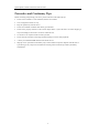
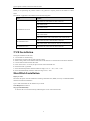
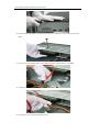
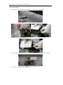
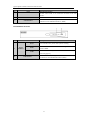
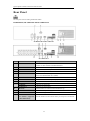
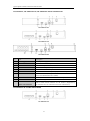
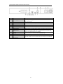
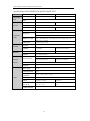
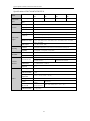
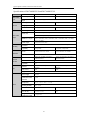
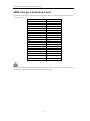
Network Video Recorder Quick Operation Guide UD.6L0202B1935A01 Quick Operation Guide of Network Video Recorder TABLE OF CONTENTS NVR Installation .............................................................................................................................................. 6 Hard Disk Installation ..................................................................................................................................... 6 Front Panel ....................................................................................................................................................... 9 DS-8600NI-E8 ................................................................................................................................... 9 DS-7700NI-E4(/P) ........................................................................................................................... 11 DS-7600NI-E1/E2 Series ................................................................................................................. 13 Rear Panel ...................................................................................................................................................... 14 DS-8600NI-E8, DS-7700NI-E4 and DS-7700NI-E4/P .................................................................... 14 DS-7600NI-E1, DS-7600NI-E1/4N, DS-7600NI-E2 and DS-7600NI-E2/8N ................................. 15 DS-7600NI-E1/4P and DS-7600NI-E2/8P ....................................................................................... 15 Peripheral Connections ................................................................................................................................. 17 Wiring of Alarm Input .............................................................................................................................. 17 Wiring of Alarm Output ........................................................................................................................... 17 Using of Alarm Connectors ...................................................................................................................... 17 Specifications .................................................................................................................................................. 18 Specifications of DS-8600NI-E8 ............................................................................................................. 18 Specifications of DS-7700NI-E4 ............................................................................................................. 19 Specifications of DS-7700NI-E4/P .......................................................................................................... 20 Specifications of DS-7600NI-E2 ............................................................................................................. 21 Specifications of DS-7600NI-E1 ............................................................................................................. 22 Specifications of DS-7604NI-E1/N and DS-7608NI-E2/N ...................................................................... 23 Specifications of DS-7616&7632NI-E2/N............................................................................................... 24 Specifications of DS-7604NI-E1/P and DS-7608NI-E2/P ....................................................................... 25 Specifications of DS-7616&7632NI-E2/P ............................................................................................... 26 HDD Storage Calculation Chart ................................................................................................................... 27 Menu Operation ............................................................................................................................................. 28 Menu Structure......................................................................................................................................... 28 Startup and Shutdown .............................................................................................................................. 28 Setting the Admin Password .................................................................................................................... 29 Login and Logout ..................................................................................................................................... 30 User Login ....................................................................................................................................... 30 User Logout ..................................................................................................................................... 30 Live View ................................................................................................................................................. 31 Adding IP Cameras .................................................................................................................................. 31 Recording ................................................................................................................................................. 34 Instant Recording ............................................................................................................................. 34 All-day Recording ............................................................................................................................ 34 Playback ................................................................................................................................................... 34 Backup ..................................................................................................................................................... 36 VCA Detection ......................................................................................................................................... 37 VCA Search ............................................................................................................................................. 38 Accessing by Web Browser ............................................................................................................................ 39 Logging In................................................................................................................................................ 39 Live View ................................................................................................................................................. 40 Recording ................................................................................................................................................. 41 Playback ................................................................................................................................................... 43 1 Quick Operation Guide of Network Video Recorder Quick Start Guide COPYRIGHT ©2015 Hangzhou Hikvision Digital Technology Co., Ltd. ALL RIGHTS RESERVED. Any and all information, including, among others, wordings, pictures, graphs are the properties of Hangzhou Hikvision Digital Technology Co., Ltd. or its subsidiaries (hereinafter referred to be “Hikvision”). This user manual (hereinafter referred to be “the Manual”) cannot be reproduced, changed, translated, or distributed, partially or wholly, by any means, without the prior written permission of Hikvision. Unless otherwise stipulated, Hikvision does not make any warranties, guarantees or representations, express or implied, regarding to the Manual. About this Manual This Manual is applicable to Network Video Recorder (NVR). The Manual includes instructions for using and managing the product. Pictures, charts, images and all other information hereinafter are for description and explanation only. The information contained in the Manual is subject to change, without notice, due to firmware updates or other reasons. Please find the latest version in the company website (http://overseas.hikvision.com/en/). Please use this user manual under the guidance of professionals. Trademarks Acknowledgement and other Hikvision’s trademarks and logos are the properties of Hikvision in various jurisdictions. Other trademarks and logos mentioned below are the properties of their respective owners. Legal Disclaimer TO THE MAXIMUM EXTENT PERMITTED BY APPLICABLE LAW, THE PRODUCT DESCRIBED, WITH ITS HARDWARE, SOFTWARE AND FIRMWARE, IS PROVIDED “AS IS”, WITH ALL FAULTS AND ERRORS, AND HIKVISION MAKES NO WARRANTIES, EXPRESS OR IMPLIED, INCLUDING WITHOUT LIMITATION, MERCHANTABILITY, SATISFACTORY QUALITY, FITNESS FOR A PARTICULAR PURPOSE, AND NON-INFRINGEMENT OF THIRD PARTY. IN NO EVENT WILL HIKVISION, ITS DIRECTORS, OFFICERS, EMPLOYEES, OR AGENTS BE LIABLE TO YOU FOR ANY SPECIAL, CONSEQUENTIAL, INCIDENTAL, OR INDIRECT DAMAGES, INCLUDING, AMONG OTHERS, DAMAGES FOR LOSS OF BUSINESS PROFITS, BUSINESS INTERRUPTION, OR LOSS OF DATA OR DOCUMENTATION, IN CONNECTION WITH THE USE OF THIS PRODUCT, EVEN IF HIKVISION HAS BEEN ADVISED OF THE POSSIBILITY OF SUCH DAMAGES. REGARDING TO THE PRODUCT WITH INTERNET ACCESS, THE USE OF PRODUCT SHALL BE WHOLLY AT YOUR OWN RISKS. HIKVISION SHALL NOT TAKE ANY RESPONSIBILITES FOR ABNORMAL OPERATION, PRIVACY LEAKAGE OR OTHER DAMAGES RESULTING FROM CYBER ATTACK, HACKER ATTACK, VIRUS INSPECTION, OR OTHER INTERNET SECURITY RISKS; HOWEVER, HIKVISION WILL PROVIDE TIMELY TECHNICAL SUPPORT IF REQUIRED. SURVEILLANCE LAWS VARY BY JURISDICTION. PLEASE CHECK ALL RELEVANT LAWS IN YOUR JURISDICTION BEFORE USING THIS PRODUCT IN ORDER TO ENSURE THAT YOUR USE CONFORMS THE APPLICABLE LAW. HIKVISION SHALL NOT BE LIABLE IN THE EVENT THAT THIS PRODUCT IS USED WITH ILLEGITIMATE PURPOSES. IN THE EVENT OF ANY CONFLICTS BETWEEN THIS MANUAL AND THE APPLICABLE LAW, THE LATER PREVAILS. 2 Quick Operation Guide of Network Video Recorder Regulatory Information FCC Information FCC compliance: This equipment has been tested and found to comply with the limits for a digital device, pursuant to part 15 of the FCC Rules. These limits are designed to provide reasonable protection against harmful interference when the equipment is operated in a commercial environment. This equipment generates, uses, and can radiate radio frequency energy and, if not installed and used in accordance with the instruction manual, may cause harmful interference to radio communications. Operation of this equipment in a residential area is likely to cause harmful interference in which case the user will be required to correct the interference at his own expense. FCC Conditions This device complies with part 15 of the FCC Rules. Operation is subject to the following two conditions: 1. This device may not cause harmful interference. 2. This device must accept any interference received, including interference that may cause undesired operation. EU Conformity Statement This product and - if applicable - the supplied accessories too are marked with "CE" and comply therefore with the applicable harmonized European standards listed under the EMC Directive 2004/108/EC, the RoHS Directive 2011/65/EU. 2012/19/EU (WEEE directive): Products marked with this symbol cannot be disposed of as unsorted municipal waste in the European Union. For proper recycling, return this product to your local supplier upon the purchase of equivalent new equipment, or dispose of it at designated collection points. For more information see: www.recyclethis.info 2006/66/EC (battery directive): This product contains a battery that cannot be disposed of as unsorted municipal waste in the European Union. See the product documentation for specific battery information. The battery is marked with this symbol, which may include lettering to indicate cadmium (Cd), lead (Pb), or mercury (Hg). For proper recycling, return the battery to your supplier or to a designated collection point. For more information see: www.recyclethis.info Industry Canada ICES-003 Compliance This device meets the CAN ICES-3 (B)/NMB-3(B) standards requirements. 3 Quick Operation Guide of Network Video Recorder Safety Instruction These instructions are intended to ensure that user can use the product correctly to avoid danger or property loss. The precaution measure is divided into “Warnings” and “Cautions” Warnings: Serious injury or death may occur if any of the warnings are neglected. Cautions: Injury or equipment damage may occur if any of the cautions are neglected. Warnings Follow these Cautions Follow to these safeguards to prevent serious precautions prevent injury or death. potential injury or material damage. Warnings ● Proper configuration of all passwords and other security settings is the responsibility of the installer and/or end-user. ● In the use of the product, you must be in strict compliance with the electrical safety regulations of the nation and region. Please refer to technical specifications for detailed information. ● Input voltage should meet both the SELV (Safety Extra Low Voltage) and the Limited Power Source with 100~240 VAC or 12 VDC according to the IEC60950-1 standard. Please refer to technical specifications for detailed information. ● Do not connect several devices to one power adapter as adapter overload may cause over-heating or a fire hazard. ● Please make sure that the plug is firmly connected to the power socket. If smoke, odor or noise rise from the device, turn off the power at once and unplug the power cable, and then please contact the service center. 4 Quick Operation Guide of Network Video Recorder Preventive and Cautionary Tips Before connecting and operating your device, please be advised of the following tips: • • • • • Ensure unit is installed in a well-ventilated, dust-free environment. Unit is designed for indoor use only. Keep all liquids away from the device. Ensure environmental conditions meet factory specifications. Ensure unit is properly secured to a rack or shelf. Major shocks or jolts to the unit as a result of dropping it may cause damage to the sensitive electronics within the unit. • • • • Use the device in conjunction with an UPS if possible. Power down the unit before connecting and disconnecting accessories and peripherals. A factory recommended HDD should be used for this device. Improper use or replacement of the battery may result in hazard of explosion. Replace with the same or equivalent type only. Dispose of used batteries according to the instructions provided by the battery manufacturer. 5 Quick Operation Guide of Network Video Recorder Thank you for purchasing our product. If there is any question or request, please do not hesitate to contact dealer. This manual is applicable to the models listed in the following table. Series Models DS-7604NI-E1, DS-7608NI-E1, DS-7616NI-E1 DS-7604NI-E1/4P DS-7604NI-E1/4N DS-7600NI-E1/E2 series DS-7608NI-E2, DS-7616NI-E2, DS-7632NI-E2 DS-7608NI-E2/8P, DS-7616NI-E2/8P, DS-7616NI-E2/16P, DS-7632NI-E2/8P DS-7608NI-E2/8N, DS-7616NI-E2/8N, DS-7632NI-E2/8N DS-7708NI-E4, DS-7716NI-E4, DS-7732NI-E4 DS-7700NI-E4 series DS-7708NI-E4/8P, DS-7716NI-E4/16P, DS-7732NI-E4/16P DS-8600NI-E8 series DS-8608NI-E8, DS-8616NI-E8, DS-8632NI-E8 NVR Installation During the installation of the NVR: 1. 2. 3. 4. 5. 6. 7. 8. Use brackets for rack mounting. Ensure there is ample room for audio and video cables. When routing cables, ensure that the bend radius of the cables are no less than five times than its diameter. Connect both the alarm and RS-485 cable. Allow at least 2cm (≈0.75-inch) of space between racks mounted devices. Ensure the NVR is grounded. Environmental temperature should be within the range of -10 ºC ~ 55 ºC, 14ºF ~ 131ºF. Environmental humidity should be within the range of 10% ~ 90%. Hard Disk Installation Before you start: Disconnect the power from the NVR before installing a hard disk drive (HDD). A factory recommended HDD should be used for this installation. Up to 8 SATA hard disks can be installed on your NVR. Tools Required: Screwdriver. Steps (for DS-8600NI-E8): 1. Remove the cover from the NVR by unfastening the screws on the back and side. 6 Quick Operation Guide of Network Video Recorder 2. Install the HDD in the HDD rack using the provided screws. Fasten the screws on the button to fix the HDD. 3. Connect one end of the data cable to the motherboard of NVR and the other end to the HDD. 4. Connect the power cable to the HDD. 5. Re-install the cover of the NVR and fasten screws. 7 Quick Operation Guide of Network Video Recorder Steps (for other models): 1. Remove the cover from the NVR by unfastening the screws on the rear and side panel. 2. Connect one end of the data cable to the motherboard of NVR and the other end to the HDD. 3. Connect the power cable to the HDD. 4. Place the HDD on the bottom of the device and then fasten the screws on the bottom to fix the HDD. 5. Re-install the cover of the NVR and fasten screws. 8 Quick Operation Guide of Network Video Recorder Front Panel DS-8600NI-E8 No. Name Function Description ALARM READY Turns red when a sensor alarm is detected. Ready LED is normally blue, indicating that the device is functioning properly. Turns blue when device is controlled by an IR remote. STATUS Turns red when controlled by a keyboard and purple when IR remote and keyboard is used at the same time. 1 Status HDD Indicators MODEM Tx/Rx Flashes red when data is being read from or written to HDD. Reserved for future usage. Flashes blue when network connection is functioning properly. Guard LED turns blue when the device is in armed status; at this time, an alarm is enabled when an event is detected. GUARD The LED turns off when the device is unarmed. The arm/disarm status can be changed by pressing and holding on the ESC button for more than 3 seconds in live view mode. 2 IR Receiver Receiver for IR remote 3 DVD-R/W Slot for DVD-R/W. Switch to the corresponding channel in Live view or PTZ Control mode. Input numbers and characters in Edit mode. 4 Alphanumeric Buttons Switch between different channels in Playback mode. The light of the button is blue when the corresponding channel is recording; it is red when the channel is in network transmission status; it is pink when the channel is recording and transmitting. 5 USB Interfaces ESC Universal Serial Bus (USB) ports for additional devices such as USB mouse and USB Hard Disk Drive (HDD). Back to the previous menu. Press for Arming/disarming the device in Live View mode. Enter the Manual Record setting menu. 6 Composite REC/SHOT Keys In PTZ control settings, press the button and then you can call a PTZ preset by pressing Numeric button. It is also used to turn audio on/off in the Playback mode. PLAY/AUTO ZOOM+ The button is used to enter the Playback mode. It is also used to auto scan in the PTZ Control menu. Zoom in the PTZ camera in the PTZ Control setting. 9 Quick Operation Guide of Network Video Recorder No. Name Function Description Adjust focus in the PTZ Control menu. A/FOCUS+ It is also used to switch between input methods (upper and lowercase alphabet, symbols and numeric input). Edit text fields. When editing text fields, it will also function as a Backspace button to delete the character in front of the cursor. On checkbox fields, pressing the button will tick the checkbox. EDIT/IRIS+ In PTZ Control mode, the button adjusts the iris of the camera. In Playback mode, it can be used to generate video clips for backup. Enter/exit the folder of USB device and eSATA HDD. MAIN/SPOT/ZOO Switch between main and spot output. M- In PTZ Control mode, it can be used to zoom out the image. Select all items on the list when used in a list field. In PTZ Control mode, it will turn on/off PTZ light (if F1/ LIGHT applicable). In Playback mode, it is used to switch between play and reverse play. Cycle through tab pages. F2/ AUX In synchronous playback mode, it is used to switch between channels. Press the button will help you return to the Main menu (after successful login). Press and hold the button for 5 seconds will turn off audible key MENU/WIPER beep. In PTZ Control mode, the MENU/WIPER button will start wiper (if applicable). In Playback mode, it is used to show/hide the control interface. Switch between single screen and multi-screen mode. PREV/FOCUS- In PTZ Control mode, it is used to adjust the focus in conjunction with the A/FOCUS+ button. Enter the PTZ Control mode. PTZ/IRIS- In the PTZ Control mode, it is used to adjust the iris of the PTZ camera. The DIRECTION buttons are used to navigate between different fields and items in menus. In the Playback mode, the Up and Down button is used to speed up and slow down recorded video. The Left and Right button DIRECTION will select the next and previous record files. In Live View mode, these buttons can be used to cycle through 7 Control channels. Buttons In PTZ control mode, it can control the movement of the PTZ camera. The ENTER button is used to confirm selection in any of the menu modes. ENTER It can also be used to tick checkbox fields. In Playback mode, it can be used to play or pause the video. In single-frame Playback mode, pressing the button will advance 10 Quick Operation Guide of Network Video Recorder No. Name Function Description the video by a single frame. In Auto-switch mode, it can be used to stop /start auto switch. Move the active selection in a menu. It will move the selection up and down. In Live View mode, it can be used to cycle through different channels. 8 JOG SHUTTLE Control In the Playback mode: The outer ring is used to speed up or slow down the record files and the inner ring is used to jump 30s forward/backward in records files. In PTZ control mode, it can control the movement of the PTZ camera. 9 POWER ON/OFF Power on/off switch. DS-7700NI-E4(/P) No. Name Function Description POWER Turns green when NVR is powered up. READY The LED is green when the device is running normally. The light is green when the IR remote control is enabled; 1 STATUS Status Indicators are used; The light is out when none of the above condition is met. ALARM 2 The light is red when the function of the composite keys (SHIFT) The light is red when there is an alarm occurring. HDD Blinks red when HDD is reading/writing. Tx/Rx Blinks green when network connection is functioning normally. DVD-R/W Slot for DVD-R/W. In menu mode, the direction buttons are used to navigate between different fields and items and select setting parameters. In playback mode, the Up and Down buttons are used to speed up DIRECTION and slow down record playing, and the Left and Right buttons are used to move the recording 30s forwards or backwards. In the image setting interface, the up and down button can adjust 3 Control the level bar of the image parameters. Buttons In live view mode, these buttons can be used to switch channels. The Enter button is used to confirm selection in menu mode; or used to check checkbox fields and ON/OFF switch. ENTER In playback mode, it can be used to play or pause the video. In single-frame play mode, pressing the Enter button will play the video by a single frame. In auto sequence view mode, the buttons can be used to pause or 11 Quick Operation Guide of Network Video Recorder No. Name Function Description resume auto sequence. Switch between the numeric or letter input and functions of the SHIFT composite keys. (Input letter or numbers when the light is out; Realize functions when the light is red.) 1/MENU Enter numeral “1”; Access the main menu interface. Enter numeral “2”; Enter letters “ABC”; 2/ABC/F1 The F1 button when used in a list field will select all items in the list. In PTZ Control mode, it will turn on/off PTZ light and when the image is zoomed in, the key is used to zoom out. Enter numeral “3”; Enter letters “DEF”; 3/DEF/F2 The F2 button is used to change the tab pages. In PTZ control mode, it zooms in the image. Enter numeral “4”; 4/GHI/ESC Enter letters “GHI”; Exit and back to the previous menu. Enter numeral “5”; Composite 4 Enter letters “JKL”; Keys 5/JKL/EDIT Delete characters before cursor; Check the checkbox and select the ON/OFF switch; Start/stop record clipping in playback. Enter numeral “6”; 6/MNO/PLAY Enter letters “MNO”; Playback, for direct access to playback interface. Enter numeral “7”; 7/PQRS/REC Enter letters “PQRS”; Open the manual record interface. Enter numeral “8”; 8/TUV/PTZ Enter letters “TUV”; Access PTZ control interface. 9/WXYZ/PRE V Enter numeral “9”; Enter letters “WXYZ”; Multi-channel display in live view. Enter numeral “0”; 0/A Shift the input methods in the editing text field. (Upper and lowercase, alphabet, symbols or numeric input). Double press the button to switch the main and auxiliary output. Move the active selection in a menu. It will move the selection up and down. 5 JOG SHUTTLE Control In Live View mode, it can be used to cycle through different channels. In the Playback mode, it can be used to jump 30s forward/backward in video files. 12 Quick Operation Guide of Network Video Recorder No. Name Function Description In PTZ control mode, it can control the movement of the PTZ camera. 6 POWER ON/OFF 7 USB Interfaces Power on/off switch. Universal Serial Bus (USB) ports for additional devices such as USB mouse and USB Hard Disk Drive (HDD). DS-7600NI-E1/E2 Series No. Name Description Power 1 Status Indicator Status Tx/Rx Power indicator turns yellow when system is running. Status indicator blinks red when data is being read from or written to HDD. Tx/Rx indictor blinks yellow when network connection is functioning properly. Universal Serial Bus (USB) ports for additional devices such 2 USB Interface as USB mouse and USB Hard Disk Drive (HDD). 13 Quick Operation Guide of Network Video Recorder Rear Panel The rear panel vaires according to different models. DS-8600NI-E8, DS-7700NI-E4 and DS-7700NI-E4/P DS-8600NI-E8 and DS-7700NI-E4 DS-7700NI-E4/P No. Item Description 1 LAN Interface 1 network interface provided for DS-7700NI-E4/P and 2 network interfaces for DS-7700NI-E4 and DS-8600NI-E8. 2 AUDIO OUT RCA connector for audio output. 3 LINE IN RCA connector for audio input. 4 HDMI HDMI video output connector. 5 USB 3.0 interface Universal Serial Bus (USB) ports for additional devices such as USB mouse and USB Hard Disk Drive (HDD). 6 RS-232 Interface Connector for RS-232 devices. 7 VGA DB9 connector for VGA output. Display local video output and menu. 8 RS-485 Interface Half-duplex connector for RS-485 devices. 9 ALARM IN Connector for alarm input. ALARM OUT Connector for alarm output. 10 GROUND Ground (needs to be connected when NVR starts up). 11 AC 100V ~ 240V 100V ~ 240V AC power supply. 12 Power Switch Switch for turning on/off the device. 13 Network Interfaces with PoE function (supported Network interfaces for the cameras and to provide power over Ethernet. by DS-7700NI-E4/P) 14 Quick Operation Guide of Network Video Recorder DS-7600NI-E1, DS-7600NI-E1/4N, DS-7600NI-E2 and DS-7600NI-E2/8N DS-7600NI-E1/E2 DS-7600NI-E1/4N DS-7600NI-E2/8N No. Item Description 1 Power Supply DC 12V power supply. 2 Audio In RCA connector for audio input. 3 HDMI Interface HDMI video output connector. 4 LAN Network Interface 1 10 /100 /1000 Mbps self-adaptive Ethernet interface 5 Audio Out RCA connector for audio output. 6 VGA Interface DB9 connector for VGA output. Display local video output and menu. 7 USB Interface Universal Serial Bus (USB) ports for additional devices such as USB mouse and USB Hard Disk Drive (HDD). 8 Ground Ground (needs to be connected when NVR starts up). 9 Power Switch Switch for turning on/off the device. 10 Network Interfaces with Built-in switch network interfaces for the cameras. (Supported by built-in switch function DS-7600NI-E1/4N, DS-7600NI-E2/8N and DS-7600NI-SN/N). DS-7600NI-E1/4P and DS-7600NI-E2/8P DS-7600NI-E1/4P 15 Quick Operation Guide of Network Video Recorder DS-7600NI-E2/8P No. Item Description 1 Power Supply 48V DC power supply for DS-7600NI-E1/4P and AC 100~240V for DS-7600NI-E2/8P. 2 Audio In RCA connector for audio input. 3 HDMI Interface HDMI video output connector. 4 LAN Network Interface 1 10 /100 /1000 Mbps self-adaptive Ethernet interface 5 Audio Out RCA connector for audio output. 6 VGA Interface DB9 connector for VGA output. Display local video output and menu. 7 USB Interface Universal Serial Bus (USB) ports for additional devices such as USB mouse and USB Hard Disk Drive (HDD). 8 Ground Ground (needs to be connected when NVR starts up). 9 Power Switch Switch for turning on/off the device. 10 Network Interfaces with PoE function Network interfaces for the cameras and to provide power over Ethernet. 16 Quick Operation Guide of Network Video Recorder Peripheral Connections This section is applicable for the DS-8600NI-E8, DS-7700NI-E4 and DS-7700NI-E4/P series only. Wiring of Alarm Input The alarm input is an open/closed relay. To connect the alarm input to the device, use the following diagram. If the alarm input is not an open/close relay, please connect an external relay between the alarm input and the device. Wiring of Alarm Output To connect to an alarm output (AC or DC load), use the following diagram: DC Load Connection Diagram AC Load Connection Diagram For DC load, the jumpers can be used within the limit of 12V/1A safely. To connect an AC load, jumpers should be left open (you must remove the jumper on the motherboard in the NVR). Use an external relay for safety (as shown in the figure above). There are 4 jumpers (JP1, JP2, JP3, and JP4) on the motherboard, each corresponding with one alarm output. By default, jumpers are connected. To connect an AC load, jumpers should be removed. Example: If you connect an AC load to the alarm output 3 of the NVR, then you must remove the JP 3. Using of Alarm Connectors To connect alarm devices to the NVR: 1. Disconnect pluggable block from the ALARM IN /ALARM OUT terminal block. 2. Unfasten stop screws from the pluggable block, insert signal cables into slots and fasten stop screws. Ensure signal cables are in tight. 3. Connect pluggable block back into terminal block. 17 Quick Operation Guide of Network Video Recorder Specifications Specifications of DS-8600NI-E8 Model Video/Audio input Network DS-8608NI-E8 DS-8616NI-E8 DS-8632NI-E8 IP video input 8-ch 16-ch 32-ch Two-way audio 1-ch, RCA (2.0 Vp-p, 1KΩ) Incoming bandwidth 80Mbps Outgoing bandwidth 80Mbps Remote connection 128 Recording resolution 6MP/5MP/3MP/1080P/UXGA/720P/VGA/4CIF/DCIF/2CIF/CIF/QCIF 160Mbps 160Mbps Main stream: 50 fps (P) / 60 fps (N) Frame rate Sub-stream: 50 fps (P) / 60 fps (N) Video/Audio output HDMI/VGA output 1-ch, resolution: 1920 ×1080 /60Hz, 1600 ×1200 /60Hz, 1280 ×1024 /60Hz, 1280 ×720 /60Hz, 1024 ×768 /60Hz Audio output 1-ch, RCA (Linear, 1KΩ) Live view / Playback resolution 6MP/5MP/3MP/1080P/UXGA/720P/VGA/4CIF/DCIF/2CIF/CIF/QCIF Decoding 8-ch@720P, 16-ch@4CIF, 12-ch@720P, 6-ch@1080P Capability 6-ch@1080P Hard disk External interface Others SATA 8 SATA interfaces for 4 HDDs + 1 DVD-R/W (default), or 8HDDs eSATA (Optional) 1 eSATA interface Capacity Up to 6TB capacity for each HDD Network interface 2 RJ-45 10 /100 /1000 Mbps self-adaptive Ethernet interfaces Serial interface RS-232 and RS-485 USB interface 2 ×USB 2.0 + 1 ×USB 3.0 Alarm in / out 16 / 4 (optionally can be expanded to 16 / 8) Power supply 100 ~ 240 VAC Consumption (without hard disk or DVD-R/W) ≤ 20 W Working temperature -10 ºC ~ +55 ºC (14ºF ~ 131ºF) Working humidity 10 % ~ 90 % Chassis 19-inch rack-mounted 2U chassis Dimensions (W × D × H) 445 ×470 ×70 mm ( 17.5"× 18.5" ×2.8") Weight (without hard disk or DVD-R/W ) ≤ 8 kg (17.6 lb) ≤ 20 W 18 ≤ 20 W Quick Operation Guide of Network Video Recorder Specifications of DS-7700NI-E4 Model Video/Audio input Network DS-7708NI-E4 DS-7716NI-E4 DS-7732NI-E4 IP video input 8-ch 16-ch 32-ch Two-way audio 1-ch, RCA (2.0 Vp-p, 1kΩ) Incoming bandwidth 80Mbps Outgoing bandwidth 80Mbps Remote connection 128 Recording resolution 6MP/5MP/3MP/1080P/UXGA/720P/VGA/4CIF/DCIF/2CIF/CIF/QCIF 160Mbps 160Mbps Main stream: 50 fps (P) / 60 fps (N) Frame rate Sub-stream: 50 fps (P) / 60 fps (N) Video/Audio output HDMI/VGA output 1-ch, resolution: 1920 ×1080 /60Hz, 1600 ×1200 /60Hz, 1280 ×1024 /60Hz, 1280 ×720 /60Hz, 1024 ×768 /60Hz Audio output 1-ch, RCA (Linear, 1KΩ) Live view / Playback resolution 6MP/5MP/3MP/1080P/UXGA/720P/VGA/4CIF/DCIF/2CIF/CIF/QCIF Decoding 8-ch@720P, 16-ch@4CIF, 12-ch@720P, 6-ch@1080P Capability 6-ch@1080P Hard disk External interface Others SATA 4 SATA interfaces for 2 HDDs + 1 DVD-R/W (default), or 4HDDs eSATA (Optional) 1 eSATA interface Capacity Up to 6TB capacity for each HDD Network interface 2 RJ-45 10 /100 /1000 Mbps self-adaptive Ethernet interfaces Serial interface RS-232 and RS-485 USB interface 2 ×USB 2.0 + 1 ×USB 3.0 Alarm in / out 16 / 4 (optionally can be expanded to 16 / 8) Power supply 100 ~ 240 VAC Consumption (without hard disk or DVD-R/W) ≤ 20 W Working temperature -10 ºC ~ +55 ºC (14ºF ~ 131ºF) Working humidity 10 % ~ 90 % Chassis 19-inch rack-mounted 1.5U chassis Dimensions (W × D × H) 445 ×390 ×70 mm ( 17.5"×15.3" ×2.8") Weight (without hard disk or DVD-R/W ) ≤ 4 kg (8.82 lb) ≤ 20 W 19 ≤ 20 W Quick Operation Guide of Network Video Recorder Specifications of DS-7700NI-E4/P Model Video/Audio input Network DS-7708NI-E4/8P DS-7716NI-E4/16P DS-7732NI-E4/16P IP video input 8-ch 16-ch 32-ch Two-way audio 1-ch, RCA (2.0 Vp-p, 1kΩ) Incoming bandwidth 80Mbps Outgoing bandwidth 80Mbps Remote connection 128 Recording resolution 6MP/5MP/3MP/1080P/UXGA/720P/VGA/4CIF/DCIF/2CIF/CIF/QCIF 160Mbps 160Mbps Main stream: 50 fps (P) / 60 fps (N) Frame rate Sub-stream: 50 fps (P) / 60 fps (N) Video/Audio output HDMI/VGA output 1-ch, resolution: 1920 ×1080 /60Hz, 1600 ×1200 /60Hz, 1280 ×1024 /60Hz, 1280 ×720 /60Hz, 1024 ×768 /60Hz Audio output 1-ch, RCA (Linear, 1KΩ) Live view / Playback resolution 6MP/5MP/3MP/1080P/UXGA/720P/VGA/4CIF/DCIF/2CIF/CIF/QCIF Decoding 8-ch@720P, 16-ch@4CIF, 12-ch@720P, 6-ch@1080P Capability 6-ch@1080P Hard disk External interface SATA 4 SATA interfaces for 2 HDDs + 1 DVD-R/W (default), or 4HDDs eSATA (Optional) 1 eSATA interface Capacity Up to 6TB capacity for each HDD Network interface 1 RJ-45 10 /100 /1000 Mbps self-adaptive Ethernet interface Serial interface RS-232 and RS-485 USB interface 2 ×USB 2.0 + 1 ×USB 3.0 Alarm in / out 16 / 4 (optionally can be expanded to 16 / 8) 8 independent 100 Interface 16 independent 100 Mbps PoE network interfaces interfaces PoE Others Mbps PoE network Max. Power 200W Supported standard AF and AT Power supply 100 ~ 240 VAC Consumption (without hard disk, DVD-R/W or PoE) ≤ 20 W Working temperature -10 ºC ~ +55 ºC (14ºF ~ 131ºF) Working humidity 10 % ~ 90 % Chassis 19-inch rack-mounted 1.5U chassis Dimensions (W × D × H) 445 ×390 ×70 mm ( 17.5"×15.3" ×2.8") Weight (without hard disk or DVD-R/W ) ≤ 4 kg (8.82 lb) 20 Quick Operation Guide of Network Video Recorder Specifications of DS-7600NI-E2 Model DS-7608NI-E2 DS-7616NI-E2 DS-7632NI-E2 16-ch 32-ch Video/Audio IP video input 8-ch input Two-way audio input 1-ch, RCA (2.0 Vp-p, 1KΩ) Incoming bandwidth 80Mbps Outgoing bandwidth 80Mbps Remote connection 128 Recording resolution 6MP/5MP/3MP/1080P/UXGA/720P/VGA/4CIF/DCIF/2CIF/CIF/QCIF Network 160Mbps 160Mbps Main stream: 50 fps (P) / 60 fps (N) Frame rate Sub-stream: 50 fps (P) / 60 fps (N) Video/Audio HDMI/VGA output 1-ch, resolution: 1920 ×1080 /60Hz, 1600 ×1200 /60Hz, 1280 ×1024 /60Hz, 1280 ×720 /60Hz, 1024 ×768 /60Hz Audio output 1-ch, RCA (Linear, 1kΩ) Live view / Playback resolution 6MP/5MP/3MP/1080P/UXGA/720P/VGA/4CIF/DCIF/2CIF/CIF/QCIF Capability 8-ch@720P, 6-ch@1080P SATA 2 SATA interfaces for 2 HDDs Capacity Up to 6TB for each disk Network interface 1 RJ-45 10 /100 /1000 Mbps self-adaptive Ethernet interface USB interface 1 ×USB 2.0 and 1 × USB 3.0 Alarm in/out (Optional) 4/1 Power supply 12V DC Consumption (without hard disk) ≤ 10W Working temperature -10 ºC ~ +55 ºC (+14 ºF~ + 131 ºF) Working humidity 10 % ~ 90 % Chassis 380 chassis Dimensions (W × D × H) 380 ×290 ×48mm (15.0" ×11.4" ×1.9") Weight (without hard disk) ≤ 1 kg (2.2 lb) output Decoding 16-ch@4CIF, 12-ch@720P, 6-ch@1080P Hard disk External interface Others 21 Quick Operation Guide of Network Video Recorder Specifications of DS-7600NI-E1 Model DS-7604NI-E1 DS-7608NI-E1 DS-7616NI-E1 8-ch 16-ch Video/Audio IP video input 4-ch input Two-way audio input 1-ch, RCA (2.0 Vp-p, 1KΩ) Incoming bandwidth 40Mbps Outgoing bandwidth 80Mbps Remote connection 32 Recording resolution 6MP/5MP/3MP/1080P/UXGA/720P/VGA/4CIF/DCIF/2CIF/CIF/QCIF Network 80Mbps 160Mbps 128 128 Main stream: 50 fps (P) / 60 fps (N) Frame rate Video/Audio Sub-stream: 50 fps (P) / 60 fps (N) HDMI/VGA output 1-ch, resolution: 1920 ×1080 /60Hz, 1600 ×1200 /60Hz, 1280 ×1024 /60Hz, 1280 ×720 /60Hz, 1024 ×768 /60Hz Audio output 1-ch, RCA (Linear, 1kΩ) Live view / Playback resolution 6MP/5MP/3MP/1080P/UXGA/720P/VGA/4CIF/DCIF/2CIF/CIF/QCIF Capability 4-ch@1080P SATA 1 SATA interface for 1 HDD Capacity Up to 6TB for each disk Network interface 1 RJ-45 10 /100 /1000 Mbps self-adaptive Ethernet interface USB interface 1 ×USB 2.0 and 1 × USB 3.0 Alarm in/out (Optional) 4/1 Power supply 12V DC Consumption (without hard disk) ≤ 10W Working temperature -10 ºC ~ +55 ºC (+14 ºF~ + 131 ºF) Working humidity 10 % ~ 90 % Chassis Standalone 1U chassis Dimensions (W × D × H) 315 ×230 ×45 mm (12.4" × 9.0" ×1.8") Weight (without hard disk) ≤ 1 kg (2.2 lb) output Decoding 8-ch@720P, 6-ch@1080P 16-ch@4CIF, 12-ch@720P, 6-ch@1080P Hard disk External interface Others 22 Quick Operation Guide of Network Video Recorder Specifications of DS-7604NI-E1/N and DS-7608NI-E2/N Model DS-7604NI-E1/4N DS-7608NI-E2/8N 8-ch Video/Audio IP video input 4-ch input Two-way audio input 1-ch, RCA (2.0 Vp-p, 1kΩ) Incoming bandwidth 40Mbps Outgoing bandwidth 80Mbps Remote connection 32 Recording resolution 6MP/5MP/3MP/1080P/UXGA/720P/VGA/4CIF/DCIF/2CIF/CIF/QCIF Network 80Mbps 128 Main stream: 50 fps (P) / 60 fps (N) Frame rate Video/Audio Sub-stream: 50 fps (P) / 60 fps (N) HDMI/VGA output 1-ch, resolution: 1920 ×1080 /60Hz, 1600 ×1200 /60Hz, 1280 ×1024 /60Hz, 1280 ×720 /60Hz, 1024 ×768 /60Hz Audio output 1-ch, RCA (Linear, 1kΩ) Live view / Playback resolution 6MP/5MP/3MP/1080P/UXGA/720P/VGA/4CIF/DCIF/2CIF/CIF/QCIF Capability 4-ch@1080P 8-ch@720P, 6-ch@1080P SATA 1 SATA interface for 1 HDD 2 SATA interfaces for 2 HDDs Capacity Up to 4TB for each disk output Decoding Hard disk 1 RJ-45 10 /100 /1000 Mbps self-adaptive Ethernet interface Network interface 4 independent 100 Mbps built-in switch network interfaces USB interface 1 ×USB 2.0 and 1 × USB 3.0 Alarm in/out (Optional) 4/1 Power supply 12V DC Consumption (without hard disk) ≤10W Working temperature -10 ºC ~ +55 ºC (+14 ºF~ + 131 ºF) Working humidity 10 % ~ 90 % Chassis Standalone 1U chassis 380 chassis Dimensions (W × D × H) 315×230×45mm (12.4"×9.1"×1.8") 380 ×290 ×48mm (15.0" ×11.4" × 1.9") Weight (without hard disk) ≤ 1 kg (2.2 lb) External interface Others 23 8 independent 100 Mbps built-in switch network interfaces Quick Operation Guide of Network Video Recorder Specifications of DS-7616&7632NI-E2/N DS-7616NI-E2/ DS-7632NI-E2/ DS-7616NI-E2/ DS-7632NI-E2/ 8N 8N 16N 16N 32-ch 16-ch 32-ch Model Video/Audio IP video input 16-ch input Two-way audio input 1-ch, RCA (2.0 Vp-p, 1kΩ) Incoming bandwidth 160Mbps Outgoing bandwidth 80Mbps Remote connection 128 Recording resolution 6MP/5MP/3MP/1080P/UXGA/720P/VGA/4CIF/DCIF/2CIF/CIF/QCIF Network Main stream: 50 fps (P) / 60 fps (N) Frame rate Video/Audio Sub-stream: 50 fps (P) / 60 fps (N) HDMI/VGA output 1-ch, resolution: 1920 ×1080 /60Hz, 1600 ×1200 /60Hz, 1280 ×1024 /60Hz, 1280 ×720 /60Hz, 1024 ×768 /60Hz Audio output 1-ch, RCA (Linear, 1kΩ) Live view / Playback resolution 6MP/5MP/3MP/1080P/UXGA/720P/VGA/4CIF/DCIF/2CIF/CIF/QCIF Capability 16-ch@4CIF, 12-ch@720P, 6-ch@1080P SATA 2 SATA interfaces for 2 HDDs Capacity Up to 6TB for each disk output Decoding Hard disk 1 RJ-45 10 /100 /1000 Mbps self-adaptive Ethernet interface Network interface 8 independent 100 Mbps built-in switch network interfaces USB interface 1 ×USB 2.0 and 1 × USB 3.0 Alarm in/out (Optional) 4/1 Power supply 12V DC Consumption (without hard disk) ≤10W Working temperature -10 ºC ~ +55 ºC (+14 ºF~ + 131 ºF) Working humidity 10 % ~ 90 % Chassis Standalone 1U chassis 380 chassis Dimensions (W × D × H) 315×230×45mm (12.4"×9.1"×1.8") 380 ×290 ×48mm (15.0" ×11.4" ×1.9") Weight (without hard disk) ≤ 1 kg (2.2 lb) External interface Others 24 16 independent 100 Mbps built-in switch network interfaces Quick Operation Guide of Network Video Recorder Specifications of DS-7604NI-E1/P and DS-7608NI-E2/P Model DS-7604NI-E1/4P DS-7608NI-E2/8P 8-ch Video/Audio IP video input 4-ch input Two-way audio input 1-ch, RCA (2.0 Vp-p, 1kΩ) Incoming bandwidth 40Mbps Outgoing bandwidth 80Mbps Remote connection 32 Recording resolution 6MP/5MP/3MP/1080P/UXGA/720P/VGA/4CIF/DCIF/2CIF/CIF/QCIF Network 80Mbps 128 Main stream: 50 fps (P) / 60 fps (N) Frame rate Video/Audio Sub-stream: 50 fps (P) / 60 fps (N) HDMI/VGA output 1-ch, resolution: 1920 ×1080 /60Hz, 1600 ×1200 /60Hz, 1280 ×1024 /60Hz, 1280 ×720 /60Hz, 1024 ×768 /60Hz Audio output 1-ch, RCA (Linear, 1kΩ) Live view / Playback resolution 6MP/5MP/3MP/1080P/UXGA/720P/VGA/4CIF/DCIF/2CIF/CIF/QCIF Capability 4-ch@1080P 8-ch@720P, 6-ch@1080P SATA 1 SATA interface for 1 HDD 2 SATA interfaces for 2 HDDs Capacity Up to 6TB for each disk Network interface 1 RJ-45 10 /100 Mbps self-adaptive Ethernet interface USB interface 1 ×USB 2.0 and 1 × USB 3.0 Alarm in/out (Optional) 4/1 Interface 4 independent 100 Mbps PoE network interfaces 8 independent 100 Mbps PoE network interfaces Max. Power 50W 120W Supported standard AF and AT Power supply 12V DC Consumption (without hard disk and PoE) ≤10W Working temperature -10 ºC ~ +55 ºC (+14 ºF~ + 131 ºF) Working humidity 10 % ~ 90 % Chassis 1U chassis 19-inch rack-mounted 1U chassis Dimensions (W × D × H) 315 ×230 ×45mm (12.4"×9.1"×1.8") 445 ×290 ×45mm (17.5" ×11.4" × 1.8") Weight (without hard disk) ≤ 1 kg (2.2 lb) output Decoding Hard disk External interface PoE Others 25 1 RJ-45 10 /1000 Mbps self-adaptive Ethernet interface Quick Operation Guide of Network Video Recorder Specifications of DS-7616&7632NI-E2/P DS-7616NI-E2/ DS-7632NI-E2/ DS-7616NI-E2/ DS-7632NI-E2/ 8P 8P 16P 16P 32-ch 16-ch 32-ch Model Video/Audio IP video input 16-ch input Two-way audio input 1-ch, RCA (2.0 Vp-p, 1kΩ) Incoming bandwidth 160Mbps Outgoing bandwidth 80Mbps Remote connection 128 Recording resolution 6MP/5MP/3MP/1080P/UXGA/720P/VGA/4CIF/DCIF/2CIF/CIF/QCIF Network Main stream: 50 fps (P) / 60 fps (N) Frame rate Video/Audio Sub-stream: 50 fps (P) / 60 fps (N) HDMI/VGA output 1-ch, resolution: 1920 ×1080 /60Hz, 1600 ×1200 /60Hz, 1280 ×1024 /60Hz, 1280 ×720 /60Hz, 1024 ×768 /60Hz Audio output 1-ch, RCA (Linear, 1kΩ) Live view / Playback resolution 6MP/5MP/3MP/1080P/UXGA/720P/VGA/4CIF/DCIF/2CIF/CIF/QCIF Capability 16-ch@4CIF, 12-ch@720P, 6-ch@1080P SATA 2 SATA interfaces for 2 HDDs Capacity Up to 6TB for each disk Network interface 1 RJ-45 10 /100 /1000 Mbps self-adaptive Ethernet interface USB interface 1 ×USB 2.0 and 1 × USB 3.0 Alarm in/out (Optional) 4/1 Interface 8 independent 100 Mbps PoE network interfaces 16 independent 100 Mbps PoE network interfaces Max. Power 120W 200W Supported standard AF and AT Power supply 100~240V AC Consumption (without hard disk and PoE) ≤10W Working temperature -10 ºC ~ +55 ºC (+14 ºF~ + 131 ºF) Working humidity 10 % ~ 90 % Chassis 380 chassis Dimensions (W × D × H) 380 ×290 ×48mm (15.0" ×11.4" ×1.9") Weight (without hard disk) ≤ 1 kg (2.2 lb) output Decoding Hard disk External interface PoE Others ≤15W 26 Quick Operation Guide of Network Video Recorder HDD Storage Calculation Chart The following chart shows an estimation of storage space used based on recording at one channel for an hour at a fixed bit rate. Bit Rate 96K 128K 160K 192K 224K 256K 320K 384K 448K 512K 640K 768K 896K 1024K 1280K 1536K 1792K 2048K Storage Used 42M 56M 70M 84M 98M 112M 140M 168M 196M 225M 281M 337M 393M 450M 562M 675M 787M 900M 4096K 1.8G 8192K 3.6G 16384K 7.2G Please note that supplied values for storage space used is just for reference. The storage values in the chart are estimated by formulas and may have some deviation from actual value. 27 Quick Operation Guide of Network Video Recorder Menu Operation Menu Structure The menu structure is shown as follows: Menu Playback Export VCA Search Manual HDD Record Camera Configuration Maintenance Shutdown Normal Normal Behavior Search Record General Schedule Camera General System Info Logout Event Event Face Search Alarm Advanced Parameters OSD Network Log Information Shutdown Reboot Tag People Counting Advanced Image Alarm Import/ Export Smart Heat Map Holiday PTZ RS-232 Upgrade Motion Live View Default Privacy Mask Exceptions Net Detect Video Tampering User HDD Detect Video Loss Hot Spare Sub-periods External File VCA The RS-232 is not available by the menu of DS-7600NI-E1/E2 series NVR. Startup and Shutdown Proper startup and shutdown procedures are crucial to expanding the life of the NVR. To start your NVR: Steps: 1. Check the power supply is plugged into an electrical outlet. It is HIGHLY recommended that an Uninterruptible Power Supply (UPS) be used in conjunction with the device. The Power button (for the DS-8600 series NVR) on the front panel should be red, indicating the device gets the power supply. 2. Press the POWER button on the front panel. The Power LED should turn blue (for the DS-8600-E8 series NVR) or green (for the DS-7700NI-E4(P) and DS-7600NI-E1/E2 series NVR). The unit will begin to start. After the device starting up, the wizard will guide you through the initial settings, including modifying password, date and time settings, network settings, HDD initializing, and recording. To shut down the NVR: Steps: 1. Enter the Shutdown menu. Menu > Shutdown 28 Quick Operation Guide of Network Video Recorder 2. Select the Shutdown button. 3. Click the Yes button. 4. Turn off the power switch on the rear panel when the attention pops up. Setting the Admin Password Purpose: For the first-time access, you need to activate the device by setting an admin password. No operation is allowed before activation. You can also activate the device via Web Browser, SADP or Client Software. Steps: 1. Input the same password in the text field of Create New Password and Confirm New Password. STRONG PASSWORD RECOMMENDED– We highly recommend you create a strong password of your own choosing (using a minimum of 8 characters, including upper case letters, lower case letters, numbers, and special characters) in order to increase the security of your product. And we recommend you reset your password regularly, especially in the high security system, resetting the password monthly or weekly can better protect your product. 2. Click OK to save the password and activate the device. For the old version device, if you update it to the new version, the following dialog box will pop up once the device starts up. You can click YES and follow the wizard to set a strong password. 29 Quick Operation Guide of Network Video Recorder Login and Logout User Login Purpose: If NVR has logged out, you must login the device before operating the menu and other functions. Steps: 1. Select the User Name in the dropdown list. 2. Input Password. 3. Click OK to log in. The device gets locked for 60 seconds if the admin user performs 7 failed password attempts (5 attempts for the guest/operator). User Logout Purpose: After logging out, the monitor turns to the live view mode and if you want to do some operation, you need to enter user name and password tog in again. Steps: 1. Enter the Shutdown menu. Menu > Shutdown 30 Quick Operation Guide of Network Video Recorder 2. Click Logout. After you have logged out the system, menu operation on the screen is invalid. It is required to input a user name and password to unlock the system. Live View Some icons are provided on screen in Live View mode to indicate different camera status. These icons include: Live View Icons In the live view mode, there are icons at the upper-right corner of the screen for each channel, showing the status of the record and alarm in the channel, so that you can find problems as soon as possible. Alarm (video loss, tampering, motion detection, VCA or sensor alarm) Record (manual record, continuous record, motion detection, VCA and alarm triggered record) Alarm & Record Event/Exception (event and exception information, appears at the lower-left corner of the screen.) Adding IP Cameras Purpose: Before you can get a live view or record of the video, you should add the network cameras to the connection list of the device. Before you start: Ensure the network connection is valid and correct, and the IP camera to add has already been activated. Please refer to the User Manual for activating the inactive IP camera. You can select one of the following three options to add the IP camera. OPTION 1: Steps: 1. Click to select an idle window in the live view mode. 2. Click the icon in the center of the windw to pop up the adding IP camera interface. 31 Quick Operation Guide of Network Video Recorder 3. Select the detected IP camera and click the Add button to add it directly, and you can click the Search button to refresh the online IP camera manually. Or you can choose to custom add the IP camera by editing the parameters in the corresponding textfiled and then click the Add button to add it. OPTION 2: Steps: 1. Select the Add IP Camera option from the right-click menu in live view mode or click Menu> Camera> Camera to enter the IP camera management interface. 2. The online cameras with same network segment will be detected and displayed in the camera list. 3. Select the IP camera from the list and click the button to add the camera. Or you can click the One-touch Adding button to add all cameras from the list. OPTION 3: Steps: 1) On the IP Camera Management interface, click the Custom Adding button to pop up the Add IP Camera (Custom) interface. 32 Quick Operation Guide of Network Video Recorder 2) You can edit the IP address, protocol, management port, and other information of the IP camera to be added. 3) Click Add to add the camera. For the successfully added IP cameras, the Security status shows the security level of the password of camera: strong password, weak password and risk password. Explanation of the icons Icon Explanation Icon Edit basic parameters of the camera Explanation Add the detected IP camera. The camera is disconnected; you can click the icon to get the exception Delete the IP camera information of camera. Play the live video of the connected Advanced settings of the camera. camera. Show the security status of the camera Upgrade the connected IP camera. Security to be active/inactive or the password strength (strong/medium/weak/risk) 33 Quick Operation Guide of Network Video Recorder Recording Before you start: Make sure that the HDD has already been installed. If not, please install a HDD and initialize it. You can refer to the user manual for detailed information. Purpose: Two kinds of record types are introduced in the following section, including Instant Record and All-day Record. And for other record types, you may refer to the user manual for detailed information. After rebooting all the manual records enabled are canceled. Instant Recording On the live view window of each channel, there is a quick setting toolbar which shows on the bottom of the window when you click on it. Click the icon to enable the record, and the icon turns to then the icon turns to . And click icon to disable the record, . All-day Recording Steps: 1. On the live view window, right lick the window and move the cursor to the Start Recording option, and select Continuous Record or Motion Detection Record on your demand. 2. And click the Yes button in the popup Attention message box to confirm the settings. Then all the channels will start to record in the selected mode. Playback Play back the record files of a specific channel in the live view menu. Channel switch is supported. Option 1: Choose a channel under live view using the mouse and click the button in the shortcut operation menu. Only record files recorded during the past five minutes on this channel will be played back. 34 Quick Operation Guide of Network Video Recorder Option 2: Steps: 1. Enter the Playback menu. Mouse: right click a channel in live view mode and select Playback from the menu. Front Panel (not applicable for the DS-7600NI-E1/E2 series): press PLAY button to play back record files of the channel under single-screen live view. Under multi-screen live view, record files of the selected channel will be played back. Pressing numerical buttons will switch playback to related channels during playback process. 2. Playback management. The toolbar in the bottom part of Playback interface can be used to control playing process. 35 Quick Operation Guide of Network Video Recorder Just check the channel or channels if you want to switch playback to another channel or execute simultaneous playback of multiple channels. Backup Recorded files can be backed up to various devices, such as USB flash drives, USB HDDs or a DVD writer. Steps: 1. Enter Video Export interface. Choose the channel(s) you want to back up and click on the Quick Export button. 2. Enter Export interface, choose backup device and click Export button to start exporting. 3. Check backup result. 36 Quick Operation Guide of Network Video Recorder VCA Detection Purpose: The NVR supports the VCA detection alarm (face detection, vehicle detection, line crossing detection and intrusion detection, region entrance detection, region exiting detection, loitering detection, people gathering detection, fast moving detection, parking detection, unattended baggage detection, object removal detection, audio loss exception detection, sudden change of sound intensity detection, and defocus detection) sent by IP camera. The VCA detection must be enabled and configured on the IP camera settings interface first. Steps: 1. Enter VCA Alarm interface of Camera Management and select a camera you want to detect VCA alarm. Menu > Camera > VCA 2. Enable the VCA detection and configure the rule settings. Please refer to the User Manual for detailed instructions. VCA detection is only supported by DS-7700NI/E4(P) and DS-8600NI-E8. For detailed steps, please refer to the User Manual for detailed instructions to set the VCA rules. 37 Quick Operation Guide of Network Video Recorder VCA Search The NVR supports the VCA search for the behavior analysis, face capture, people counting and heat map. Face Search: Search the captured face picture results triggered by face detection. Behavior Search: Search and view the behavior detection (including the line crossing detection, intrusion detection, unattended baggage detection, etc.) results in pictures and video files. Plate Search: You can search and view the matched captured vehicle plate picture and related information according to the plate searching conditions including the start time/end time, country and plate No.. People Counting: Calculate the number of people entered or exited from a certain configured area and show in chart of daily/weekly/monthly/annual report. Heat Map: Analyze the visit times and dwell time of customers in a configured area. The heat map is a graphical representation of data represented by colors. VCA search is only supported by DS-7700NI/E4(P) and DS-8600NI-E8. For detailed steps, please refer to the User Manual for detailed instructions of VCA Search. 38 Quick Operation Guide of Network Video Recorder Accessing by Web Browser You shall acknowledge that the use of the product with Internet access might be under network security risks. For avoidance of any network attacks and information leakage, please strengthen your own protection. If the product does not work properly, please contact with your dealer or the nearest service center. Logging In You can get access to the device via web browser. You may use one of the following listed web browsers: Internet Explorer 6.0, Internet Explorer 7.0, Internet Explorer 8.0, Internet Explorer 9.0, Internet Explorer 10.0, Apple Safari, Mozilla Firefox, and Google Chrome. The supported resolutions include 1024*768 and above. Steps: 1. Open web browser, input the IP address of the device and then press Enter. 2. Login to the device. If the device has not been activated, you need to activate the device first before login. 1) Set the password for the admin user account. 2) Click OK to login to the device. STRONG PASSWORD RECOMMENDED– We highly recommend you create a strong password of your own choosing (using a minimum of 8 characters, including upper case letters, lower case letters, numbers, and special characters) in order to increase the security of your product. And we recommend you reset your password regularly, especially in the high security system, resetting the password monthly or weekly can better protect your product. If the device is already activated, enter the user name and password in the login interface, and click the Login button. 3. Install the plug-in before viewing the live video and managing the camera. Please follow the installation 39 Quick Operation Guide of Network Video Recorder prompts to install the plug-in. You may have to close the web browser to finish the installation of the plug-in. Live View The live view interface appears by default when you log in the device. 2 1 4 3 The live view interface may differ according to different models. Interface Introduction No. Name 1 Channel List 2 3 Live View Window Play Control Bar Description Displays the list of channels and the playing and recording status of each channel. Displays the image of channel, and multi-window division is supported. Play control operations are supported. Pan, tilt, zoom operations are supported, as well as preset editing and 4 PTZ Control calling. PTZ function can only be realized if the connected camera supports PTZ control. The PTZ control is supported by the DS-8600NI-E8 and DS-7700NI-E4(P) series NVR only. Start Live View Steps: 1. In the live view window, select a playing window by clicking the mouse. 2. Double click a camera from the device list to start the live view. 3. You can click the button on the toolbar to start the live view of all cameras on the device list. Refer to the following table for the description of buttons on the live view window: 40 Quick Operation Guide of Network Video Recorder Icon Description Icon Select the window-division mode / Start/Stop all live view / Description / Capture pictures in the live view Start/Stop all recording / Previous/Next page / Start/Stop two-way Audio Adjust volume mode / Open/Close audio Enable/Disable digital zoom Full screen Select different stream type for live view by clicking the icon : live view in main stream; : live view in sub stream; Recording Before you start Make sure the device is connected with HDD or network disk, and the HDD or network disk has been initialized for the first time to use. Two recording types can be configured: Manual and Scheduled. The following section introduces the configuration of scheduled recording. Steps: 1. Click Configuration > Storage > Schedule Settings to enter Schedule Settings interface. 2. Select the camera to configure the record schedule. 3. Check the checkbox of Enable to enable recording schedule. 4. Choose the day in a week configure the recording schedule. 1) Click a day to set the start time and end time for recording. 41 Quick Operation Guide of Network Video Recorder 2) Select the Record Type for the period. The record type can be Schedule, Motion, Alarm, Motion & Alarm, Motion | Alarm and Event. 3) Click Save to save the settings. 4) Click the required. 5) Click OK to save the settings. icon of the day to copy the settings of current day to other days of the week if 5. Click Advanced to configure advanced record parameters, and click the OK button to save the settings. 6. You can click to configure advanced record parameters to copy the schedule of current camera to other cameras. 7. Click Save to activate the above settings. 42 Quick Operation Guide of Network Video Recorder Playback The playback interface may differ according to different models. Interface Introduction No. Name Description 1 Channel List Displays the list of channels and the playing status of each channel. Playback Displays the image of channel. 2 Window 3 Play Control Bar Play control operations are supported. 4 Time Line Displays the time bar and the records marked with different colors. 5 Playback Status 6 Calendar Displays the playback status, including channel number and playback speed. You can select the date to play. Start Playback Steps: 1. Click Playback on the menu bar to enter playback interface. 2. Click the camera from the device list for playback. 3. Select the date from the calendar and click Search. 4. Click the Play button to play the video file searched on the current date. 5. Use the buttons on the toolbar to operate in playback mode. Button Description Button / Play/Pause Stop Speed down Speed up Play by single frame Capture 43 Description Quick Operation Guide of Network Video Recorder Button Description Button Stop all playback / Download Start/Stop video clipping / Full screen 6. Description Open/Close audio Reverse playback You can drag the progress bar with the mouse to locate the exact playback point. You can also input the time in the textbox and click button to locate the playback point. The color of the video on the progress bar stands for the different video types. 0303001050324 44 Quick Operation Guide of Network Video Recorder 0300061040722 45