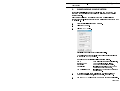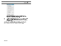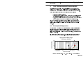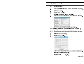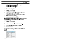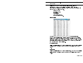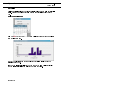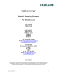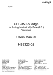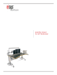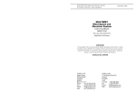
1
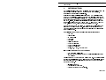
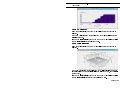
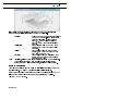
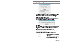
December 2001 Rainfall Logging System User Manual RAINFALL LOGGING SYSTEM V12 Application Software User Manual HB 3207-08 COPYRIGHT The copyright in this document which contains proprietary information is vested in CASELLA CEL. The contents of this document must not be used for purposes other than that for which it has been supplied or reproduced or disclosed wholly or in part without the prior written permission of CASELLA CEL CASELLA CEL Regent House Wolseley Road Kempston Bedford MK42 7JY U.K. Telephone: +44 (0) 1234 844 100 Fax: +44 (0) 1234 841 490 E-mail [email protected] Web: www.casellagroup.com CASELLA USA 17 Old Nashua Road #15 Amherst NH 03031 U.S.A. Toll Free: +1 800 366 2966 Fax: +1 603 672 8053 E-mail: [email protected] Web: www.casellaUSA.com Contents Rainfall Logging System User Manual CONTENTS . . . . . . . . . . . . . . . . PAGE 1. 2. INTRODUCTION . . . . . . . . . . . . . . . . . . . . . . . . . . . TM INSTALLATION / UN-INSTALLATION ON WINDOWS 98, ME, NT 4 & 2000 3 95, . . . . . . . . . . . . . . . . . . . . . . . . 5 . . . . . . . . . . . . . . . . . . . . . . . . . 5 2.1 Installation 2.2 Un-Installation . . . . . . . . . . . . . . . . . . . . . . . 6 2.3 Starting the System for the First Time . . . . . . . . . . . 6 3. CONFIGURING YOUR SYSTEM . . . . . . . . . . . . . . . . . . 7 4. THE TIPPING BUCKET RAIN GAUGE . . . . . . . . . . . . . . . . 9 5. 4.1 Principles of Operation . . . . . . . . . . . . . . . . . . . 4.2 Construction 4.3 Preparing the Rain Gauge for Use . . . . . . . . . . . . . . . . . . . . . . . CONNECTING BETWEEN RAIN GAUGE AND PC 5.1 7. . . . . . . . . 10 13 Temporary Connection Between a Rain Gauge and Laptop PC 5.2 6. . . . . . . . . . . . . 9 10 . . . . . . . . . . . . . . . . . . . . . . 13 Permanaent Connection Between a Rain Gauge and PC 14 OPERATION . . . . . . . . . . . . . . . . . . . . . . . . . . . . 15 6.1 Displaying the Current Rain Gauge Status . . . . . . . . 15 6.2 Downloading Data 16 6.3 Initialising the Rain Gauge . . . . . . . . . . . . . . . . 16 6.4 Viewing Data . . . . . . . . . . . . . . . . . . . . . . . 16 6.5 File Menu Options 6.6 Maintenance SERVICING Page 2 of 24 . . . . . . . . . . . . . . . . . . . . . . . . . . . . . . . . . . . . . . . . 21 . . . . . . . . . . . . . . . . . . . . . . . 22 . . . . . . . . . . . . . . . . . . . . . . . . . . . . 23 Rainfall Logging System - Introduction User Manual 1. INTRODUCTION The Casella Rainfall Logging System application software provides users with a powerful and versatile Windows program for the accumulation, processing and presentation of rainfall data. Replacing the earlier Casella rainfall logging system RLS (Rainfall Logging System) DOS application, Version 12 has been completely rewritten to take advantage of the 32 bit facilities available from current versions of Windows and provide greater ease of use. The software integrates the functions of data down- loading, archiving and historical presentation into an easily used package. It is designed to run on Windows 95, Windows 98, Windows NT 4, Windows ME, Windows 2000 and Windows XP. The software can be used on a laptop PC that is taken to the location of the rain gauge to download stored data. It can also be used in arrangements where the rain gauge is permanently connected directly to a PC located in a nearby sheltered area. The application software offers the following presentation features: ¤ Summary ¤ Minute table ¤ 15 Minute table ¤ Hour table ¤ Day table ¤ Daily hour histogram ¤ Month day histogram ¤ Month hourly rain graph ¤ Maximum hourly rate ¤ Totals, Day, Week, Month and Year Plus the following features for User Convenience: ¤ Comprehensive on-line help ¤ Import of data (.dat) files produced by earlier rainfall logging system RLS versions Data files created by the software have a binary format. For more information on using the rainfall logging system, please refer to the help available via the software help buttons. The following steps are recommended for getting your system started. ¤ Install the software, ¤ Configure it for your system, ¤ Specify the data you want to display. Page 3 of 24 Introduction Rainfall Logging System User Manual Page 4 of 24 Installation Rainfall Logging System User Manual 2. INSTALLATION / UN-INSTALLATION ON WINDOWSTM 95, 98, ME, NT 4 & 2000 CASELLA CEL licence this software for single-site use. For the convenience of the user, the software may be copied for back-up purposes, and installed simultaneously on one desk-top computer (the site) and one portable computer. SFT-4 System Requirements: TM IBM compatible PC with Pentium II or better processor, At least 8 MB of free RAM space, Microsoft Windows 98/ME/2000 and NT 4/95 with IE4 or later, Hard drive with at least 5 MB of free space, 1 3 /2 high density (1.4 MB) floppy disk drive for program installation, Super VGA colour monitor (1024 x 768 16 M colours recommended), Mouse or other Windows compatible pointing device, Printer - optional. Before installation, it is recommended that a back-up copy be made of the program disks. Keep the originals in a safe place and use the copies to install the software. It is also advisable to ensure that no other applications are running while installation takes place. The Setup program for the rainfall logging system will install files in the specified Program directory and the Windows\System directory. It will also add an icon to the desktop and a new folder and item to your Programs menu, either of which can be used to start the software. The application software is supplied on three 3.5" floppy disks. 2.1 Installation 1. Start Windows. 2. Insert Rainfall Logging System Disk 1 into the floppy disk drive. 3. Click the 4. Type a:\setup, where a identifies the floppy disk drive, then press Enter. 5. Start button on the task bar, then click the Run… option. Wait for the Casella welcome screen to be displayed, then follow the on-screen instructions. Once installation is complete, you will find the Rainfall Logging System icon on your Windows desktop. Page 5 of 24 Installation Rainfall Logging System User Manual 2.2 Un-Installation 1. Click the 2. Select the 3. Double click on 4. Start button on the task bar. Settings… option and click on the Control Panel option. Add/Remove Programs icon. In the list of installed software, select Rainfall Logging System and click the Add/Remove button. 5. Follow the on-screen instructions. 2.3 Starting the System for the First Time Start the Rainfall Logging System by double clicking on its desktop icon, or by using the Start\Programs... option. The Rainfall Logging System top level window will be displayed, as shown in Figure 1. As the cursor is moved to each button, the relevant function will be displayed on the message line at the bottom left of the display. When this is the first time you open newly installed software, the software must be configured to identify the rain gauge, as described in Chapter 3. Figure 1: Top level window Page 6 of 24 Configuration Rainfall Logging System User Manual 3. CONFIGURING YOUR SYSTEM Before using rainfall logging system to display data from your system, the software must be configured to recognise the rain gauge so they function together correctly. This chapter explains how to configure your system so it identifies the gauges connected. It is not necessary to have a rain gauge connected to your PC at this time. 1. Start your rainfall logging system software. 2. Select the 3. Click the File menu. New… option. This displays the Rain Gauge Configuration dialog. When rain gauges have previously been defined their data files can be opened via File/Open options. The Rain Gauge Configuration dialog offers five options. Name Used to identify the gauge or its location, Logger number A number selected in the logger, Bucket size Must match the actual bucket size, Synoptic time Identifies the start time of the 24 hour measurement day to be used, Communications Port Identifies the PC port used to connect to the rain gauge. 4. To configure the rain gauge, give it a name, edit the settings to match the particular gauge, as in the example, then click 5. Use the OK. Save as... option on the File menu to save the configuration. Page 7 of 24 Installation Rainfall Logging System User Manual Once the configuration has been saved, the rain gauge can be interrogated as described in Chapter 4 to give information on its status and to download data from its store. 6. File/Open option to obtain a Open dialog, highlight the file name of the gauge to be deleted, click the right mouse button then use the Delete option on To delete an existing rain gauge, use the standard the pop-up menu. The Rain Gauge Configuration dialog can be displayed, and edited, at any time by means the Page 8 of 24 Properties... option on the Edit menu. Tipping Bucket Rainfall Logging System User Manual 4. THE TIPPING BUCKET RAIN GAUGE Casella Tipping Bucket Rain Gauges are reliable and extremely robust devices. Some versions have a built-in logger to store rainfall data while others can have a heater fitted to the base of the unit to prevent freezing. Three main versions of tipping bucket rain gauge are available: ¤ Standard non-heated version, ¤ Standard heated version for those customers who require accurate and reliable rainfall data under more severe weather conditions, ¤ Non-heated version constructed to meet the framework directive of the UK Environment Agency for tipping bucket rain gauges. This User Manual covers only non heated Tipping Bucket Rain Gauges equipped with a built-in logger. For specific information about the other versions, please refer to the Tipping Bucket Rain Gauge User Manual: HB3166. 4.1 Principle Of Operation The rain gauges comprise a light weight injection moulded plastic divided tipping bucket assembly with stainless steel pivot pins that rest upon stainless steel pins in the support assembly. The use of pins produces a rolling rather than pivoting motion when the bucket tips, which reduces the likelihood of friction. Rain collects in one side of the bucket, which tips once a predetermined volume of water has been collected. The tipping action discharges the Tipping Bucket Rain Gauge Accuracy / 100 Tips Error Per 100 Tips 25 Max U.K recorded Devon 20 15 0.1mm Tip 0.2mm Tip 10 0.5mm Tip 5 0 1 Light Moderate Heavy Classification 10 100 Rain fall in mm/Hr 1000 WMO 5% Figure 2: Accuracy of 0.1 mm, 2.0 mm and 0.5 mm tip versions Page 9 of 24 Tipping Bucket Rainfall Logging System User Manual collected water and positions the other side of the bucket under the discharge nozzle ready for filling. Each time the bucket is tipped, a magnet within the bucket moulding closes a reed switch in the support assembly. The use of a sealed reed switch, capable of indefinite operation, ensures the instrument has a long working life. Each contact closure pulse represents a discrete amount of rainfall appropriate to the instruments calibration. These tipping pulses may be counted or recorded using a variety of methods, as described in Chapter 6. The tipping bucket mechanism is mounted inside the body on a cast aluminium-alloy base, incorporating a built-in spirit level to facilitate correct positioning. Both body and funnel are manufactured from aluminium alloy, 2 with an accurately machined septum ring with an aperture of 400 cm . The measurement accuracy for the various tip sizes is shown in Figure 2. 4.2 Construction The rain gauge is manufactured entirely from non-corrosive materials. The base and septum ring are cast in Aluminium Alloy LM25, heat treated and protectively coated. The outer ring and funnel are fabricated from aluminium alloy sheet and again protectively coated. Stainless steel mesh is employed to protect the inlet and outlet ports from the ingress of foreign bodies. 4.3 Preparing The Rain Gauge for Use Each instrument is delivered ready calibrated to indicate either 0.1 mm, 0.2 mm or 0.5 mm of rainfall each time the bucket tips. It is recommended that the rain gauge be installed in a location or enclosed compound away from access by the general public. Prepare a reasonably level site for the rain gauge paying due regard to the following points: ¤ No object should be nearer than four times its own height from the bucket. ¤ Do not locate the rain gauge in a hollow or on top of a hill. ¤ Tall buildings or belts of trees can cause turbulence and gusts which can increase or decrease the rain collected. ¤ The surrounding soil should be capable of allowing the discharged water to drain away freely. Page 10 of 24 Tipping Bucket Rainfall Logging System User Manual Warning ! The septum ring has a sharp edge and should be treated with care whenever handling the instrument. 1. Release the two catches securing the outer cover to the base of the rain gauge. 2. 3. Carefully lift off the cover and stand it in a safe place. With the base plate mounted in its correct location on site, adjust the three levelling screws until the built-in spirit level indicates that the unit is level. 4. 5. Once the unit is level secure the locknuts. It is advisable to secure the base unit permanently to a firm foundation using the two holding lugs provided. These accept either 9.5 mm or 3/8" rawl bolts. Do not over tighten the fixings. A restriction, such as an elastic band, may have been fitted to prevent the bucket from moving during transit. 6. Carefully remove any restriction and check that the bucket pivots freely. 7. Replace the outer cover of standard versions, with the catches engaged in the cutouts in the base plate. 8. Replace the outer cover of versions that meet the Environmental Agency Framework Directive, then use an Allen Key to lock the three screws that secure the cover to the base. The rain tipping bucket gauge is now ready for connection (Chapter 5) and operation (Chapter 6). Page 11 of 24 Tipping Bucket Rainfall Logging System User Manual Page 12 of 24 Connection Rainfall Logging System User Manual 5. CONNECTING BETWEEN RAIN GAUGE AND PC The link between rain gauge and PC may be temporary when a laptop PC is connected for downloading, or it can be in the form of a permanent cable connection to a PC located in some nearby sheltered area. 5.1 1. Temporary Connection Between a Rain Gauge and Laptop PC Release the two catches securing the outer cover to the base of the rain gauge. 2. 3. Carefully lift off the cover and stand it in a safe place. Unscrew the captive cover plug from the output socket on the logging module (Figure 3). 4. Use the communication cable supplied to connect between the output socket and the 9-lead communication port on your PC. The output socket has a pip to ensure correct alignment. 5. Download data from the rain gauge, display the current status and initialise the rain gauge as described in Chapter 6. When these operations are complete, disconnect the cable, replace the cover plug, then replace and re-secure the rain gauge outer cover. Output Connector to PC Captive Cover Plug Rubber Grommet RAINFALL LOGGING SYSTEM 6. Communication with PC 01087 Figure 3: The logging module Page 13 of 24 Connection Rainfall Logging System User Manual 5.2 Permanent Connection Between a Rain Gauge and PC For permanaent connection, the user can extend the communication cable up to a maximum length of 25 m. Use a suitable screened cable such as -W4/0724 and a junction box configuration. 1. Use an extended version of the communications cable, long enough to connect between the output socket on the logging module and the 9-lead communication port on your PC. 2. Release the two catches securing the outer cover to the base of the rain gauge. 3. Carefully lift off the cover and stand it in a safe place. 4. Remove and split the rubber gromet shown in Figure 3. 5. Pass the smaller connector of the extended communications cable through the grommet hole in the base plate to reach the output connector on the logging unit. 6. 7. Fit the the split grommet around the cable. Refit the grommet in its hole in the base plate, and seal it with silicone rubber compound. 8. Unscrew the captive cover plug from the output socket on the logging module (Figure 3). 9. Connect the cable to the output socket on the logging module. The output socket has a pip to ensure correct alignment. 10. Seal all weather connections using a silicone rubber compound. 11. Replace and re-secure the rain gauge outer cover. 12. Connect the other end of the extended cable to the 9-lead communication port on the PC. 13. Download data from the rain gauge, display the current status and initialise the rain gauge as described in Chapter 6. Page 14 of 24 Operation Rainfall Logging System User Manual 6. OPERATION 1. Start your rainfall logging system software as described in Chapter 2. 2. Select the 3. Click the File menu. Open… option. This displays a standard Windows Open dialog. 4. Select and open the configuration file for the connected rain gauge. The Summary for the selected rain gauge is displayed. Communication, download and data presentation can now be performed. 6.1 Displaying the Current Rain Gauge Status 1. Select the 2. Click the Instrument menu. Status… option. A window showing the current status of the rain gauge is displayed. It contains the following information. Logger number: 0 - 255, Page 15 of 24 Operation Rainfall Logging System User Manual Battery state: OK or Low, Bucket size: 0.1mm, 0.2mm or 0.5mm, Date/time of first record in the logger, Date/time of last record in the logger, Number of records in the logger, 6.2 Downloading Data 1. Select the 2. Click the Instrument menu. Download… option. All data stored in the rain gauge logger will be downloaded and merged with the data in the current data file. 3. After the download is complete, you will be offered the option to initialise the logger (see Section 6.3). 6.3 Initialising the Rain Gauge This operation (after confirmation) clears the rain gauge logger store, and sets the logger real-time clock to the date/time of the PC clock and sets the bucket size in the logger. 1. Select the 2. Click the Instrument menu. Initialise… option. A dialog is opened asking for confirmation of the option. Yes to confirm the command (or NO to abort). 3. Click 6.4 Viewing Data Once data has been downloaded, the following viewing possibilities are available. Summary Page 16 of 24 Rainfall Logging System - Operation User Manual Displays the Summary for the currently active data file, either by creating a new window or by bringing an existing window into view. This provides the following basic information on the rain gauge and the data that has been downloaded from it. Rain gauge name Logger ID number Bucket size Synoptic time Data date/time range Number of data records. Minute table The Minute Rainfall Table for the currently active data file displays all the one minute rainfall totals, a running total for the day and a cumulative total for the whole of the data range on view, in a tabular format. When this table is first displayed, it contains all the data in the file, however by changing the date/time range with the menu option View / View Range, only data from the given range will be displayed. 15 Minute table Displays a similar table to the Minute Rainfall Table, but for 15 minute rainfall totals. Data from a selected date/time range can be displayed in the same way. Hour table Displays a similar table to the Minute Rainfall Table, but for one hour rainfall totals. Data from a selected date/time range can be displayed in the same way. Page 17 of 24 Operation Rainfall Logging System User Manual Day table Displays a similar table to the Minute Rainfall Table, but for whole day rainfall totals. Data from a selected date/time range can be displayed in the same way. Daily hour histogram This menu option displays a Day To View dialog so that a day can be selected from a calendar menu. The Day Hourly Histogram for the selected day will be displayed as the rainfall for each hour. Tick the Cumulative rainfall check box on the Day To View dialog to display the cumulative rainfall for the selected day (see opposite). Page 18 of 24 Rainfall Logging System - Operation User Manual Month day histogram This menu option displays a Month To View dialog so that a month can be selected. The Month Daily Histogram for the selected month will be displayed as the rainfall for each day. Tick the Cumulative rainfall check box on the Month To View dialog to display the cumulative rainfall for the selected month. Month hourly rain graph This menu option displays a Month To View dialog so that a month can be selected. The Month Hourly graph for the selected month will be displayed as a threedimensional graph of the hourly rainfall for the selected month, as the rainfall for each hour. Tick the Cumulative rainfall check box on the Month To View dialog to display the cumulative rainfall for each day of the selected month. Page 19 of 24 Operation Rainfall Logging System User Manual It is possible to rotate, translate, scale and zoom the three-dimensional graphs so that details of interest can be seen more clearly. Rotation: Hold down both mouse buttons and either: move the mouse anti-clockwise to rotate the graph clockwise (or visa versa) or press x, y, z or e to select an axis and then move the mouse perpendicular to the axis. Translation: Press Shift and hold down both mouse buttons, then move the mouse to shift the graph. Scaling: Press Ctrl and hold down both mouse buttons, then move the mouse down to zoom in or up to zoom out. Zooming: Press Ctrl and hold down the left mouse button, then move the mouse to select Note: the area to zoom into. Translation, scaling and zooming (not rotation) can be removed by pressing r. When using a three button mouse, use either the left and right buttons together or just the middle button to rotate, translate and scale the graph. Maximum hourly rate Use this menu option to find the maximum rainfall recorded in any hour of a specified period. A Maximum Hourly Rate dialog will be displayed. Enter the date and time of the start of the period to be inspected in the fields and the date and time of the end of the period in the Click the Calculate button. Page 20 of 24 To fields. From Operation Rainfall Logging System User Manual The application then calculates the maximum hourly rainfall rate and displays it together with the start time of the hour. To repeat the calculation for another period change the search period and click Calculate again. Totals, Day, Week, Month and Year These menu options allow you to select a day, week, month or year, for which the application will calculate the total recorded rainfall. View Range This menu option allows you to select the range of the data in the currently active data view. The dialog box displayed will depend on the active view type. Select the date or date/time range required and click on 6.5 OK. File Menu Options The following additional options are available from the File menu: Export Allows the current file to be exported to other software in CSV (comma separated values) format. Import Allows data from the earlier Casellas RLS software to be merged with the data in the currently active rain gauge file. Page 21 of 24 Operation Rainfall Logging System User Manual 6.6 Maintenance Warning ! The septum ring has a sharp edge and should be treated with care whenever cleaning or handling the instrument. Periodically check for debris in the funnel and blockage of the inlet and outlet ports. Remove any debris present and clean the meshes. The water outlet on the underside of the funnel can be unscrewed allowing the inlet mesh to be removed and cleaned. If necessary, bucket surfaces can be cleaned using a mild detergent solution. Page 22 of 24 Rainfall Logging System - Servicing User Manual 7. SERVICING To ensure its conformity with the specification, this instrumentation and software is thoroughly inspected and its accuracy verified prior to dispatch. Test information is filed under the instrument serial number, which should, therefore, be quoted in any correspondence. Casella CEL undertake to rectify any defect in the instrument that is directly attributable to faulty design or assembly, and which becomes apparent during the warranty period. In order to take advantage of this warranty, the instrument must be returned, carriage paid, to the Casella CEL factory or accredited agent, where necessary repairs will be carried out. The warranty period for hardware runs for 12 months from the date of receipt of goods, with exceptions on certain specialised components supplied by other manufacturers which may be warranted for shorter or longer periods by their actual manufacturers. In all such cases, the benefit of these undertakings will be passed on to the user. Casella CELs liability is limited to items of their own manufacture, and they do not accept liability for any loss resulting from the operation or interpretation of the results from this equipment. To obtain repair under warranty or for servicing, the instrument should be packed and returned in its original packing or an equivalent to the Service Department at Bedford. Insure to full value and ship pre-paid. For repair or service outside the United Kingdom, please return to our appointed distributor. Please include a letter giving full details with your packing list. It should contain the following information: Instrument Type(s) and Serial Number(s), Customer name and address, Contact name and phone number, Details of any PC and Software involved, including Version Number(s), Reason for returning the equipment with a detailed description of the fault, List of any error messages that may have been displayed. The necessary adjustments or repairs will be carried out, and the instrument returned as soon as possible. Page 23 of 24 Servicing Rainfall Logging System User Manual Page 24 of 24