1
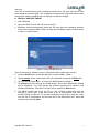
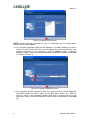
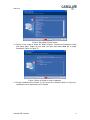
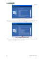
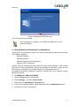
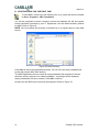
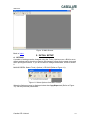
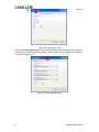
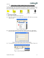
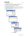
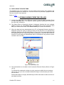
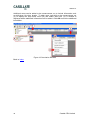
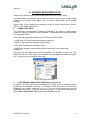
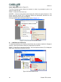
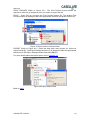
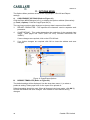
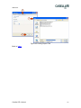
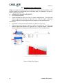
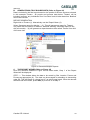
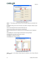
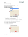
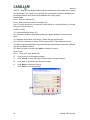
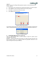
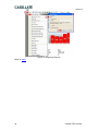
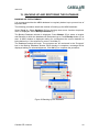
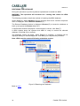
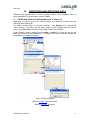
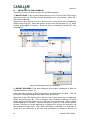
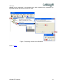
dB36 SOFTWARE INSTALLATION
AND USER MANUAL
Go to Index
CASELLA CEL
Regent House,
Wolseley Road,
Kempston,
Bedford,
MK42 7JY, U.K.
Phone: +44 (0) 1234 844 100
Fax: +44 (0) 1234 841 490
E-mail: [email protected]
Web: www.casellacel.com
CASELLA USA
17 Old Nashua Road,
# 15, Amherst,
NH 03031,
U.S.A.
Toll Free: +1 (800) 366 2966
Fax: +1 (603) 672 8053
E-mail: [email protected]
Web: www.casellaUSA.com
CASELLA ESPANA S.A.
Polígono Európolis
Calle C, nº4B
28230 Las Rozas - Madrid
Spain
Phone: + 34 91 640 75 19
Fax: + 34 91 636 01 96
E-mail: [email protected]
Web: www.casella-es.com
OCTOBER 2008
HB3342-01
HB3342-01
2
Casella CEL Limited
HB3342-01
TABLE OF CONTENTS
Back to Cover
SECTION
TITLE
PAGE
1
Before You Start
5
2
Introduction
5
3
Minimum Specification
6
4
Software Application
6
5
Initial Setup
13
6
Creating a Tree View for Data Storage
15
7
Downloading from the CEL-6X0
17
8
View Measured Data
19
9
Action Level Exceedences
25
10
Printing Data
27
11
Options Menu
30
12
Generating Reports
32
13
Backing Up and Restoring the Database
39
14
Export and Import Data
41
15
Software Warranty
44
Casella CEL Limited
3
HB3342-01
4
Casella CEL Limited
HB3342-01
1. BEFORE YOU START
Please take the time to read this section as it clarifies the terms and conventions
used in this handbook.
A. TERMINOLOGY
CEL-6X0: The CEL-6X0 sound level meter used to monitor and record noise levels.
The ‘X’ represents the instrument model e.g. CEL-620.
dB36:
The Windows application produced by Casella CEL to interface with the
instruments.
B. WINDOWS, DIALOG BOXES, BUTTONS and MENUS
Throughout this handbook the following conventions are used:
Names of buttons, menus and related items are written in Italics to distinguish them
from the surrounding text, whereas window and dialog names are written with initial
capital letters, for example:
Click the OK button to save the changes made in the Configuration dialog.
The vertical bar icon (|) is used to denote the path for hierarchical menu items, for
example:
From the Main Menu select View | Properties…
C. KEYBOARD and Mouse
Throughout this handbook the following conventions are used:
Key names are spelled with an initial capital and are underlined. A plus sign denotes
a key combination, for example:
Press Ctrl+A to select all the text in the window.
When a mouse click is indicated, the default is always a left-click unless otherwise
specified, for example:
Right-click and select Properties...
Back to Index
2. INTRODUCTION
dB36 is Casella CEL’s PC based software solution for the CEL-6X0 family of sound
level meters. It provides users with a powerful and versatile Windows based
application for the accumulation, processing, managing and presentation of noise
data.
The software integrates the functions of data downloading, archiving and octave
frequency data presentation into one easy to use package.
dB36 is built using the latest technologies from MicrosoftTM. The application itself is
designed to take advantage of the ".NET framework" and all database functions have
been implemented using SQLite.
dB36 offers the following features:
•
Cumulative record display
•
Octave data presentation
•
Tree database structure
•
Exporting of data in text and graphical formats
Casella CEL Limited
5
HB3342-01
Data managed by this application is stored in a database. This allows the raw data to
be easily migrated into other packages.
The following steps are recommended for getting your system started:
•
Prepare the Instrument as detailed in the Operator’s Manual for the CEL-6X0;
•
Install the dB36 software;
•
Configure the dB36 software for your system;
•
Specify the data you want to display.
Back to Index
3. MINIMUM PC SPECIFICATION
A. HARDWARE SPECIFICATION:
•
Pentium III - 1 GHz;
•
256 MB memory;
•
20 GB hard drive;
•
CD drive for program installation;
•
Super VGA colour monitor (1024 x 768 16M colours recommended);
•
USB communication port.
B. OPERATING SYSTEM:
• Windows Vista (service pack 1);
•
Windows XP Home or Professional;
•
Windows 2000 (service pack 4).
Back to Index
4. SOFTWARE APPLICATION
This Chapter is presented in four Sections: Install dB36 Software; Redistribution of
Microsoft Components; Uninstall dB36 Software; Starting dB36 for the First Time.
Before commencing Software Installation, it is recommended that a back-up copy be
made of the program CD. Keep the original program CD in a safe place and use the
copy to install the software. It is also advisable to ensure that no other applications
are running while installation takes place.
A full installation of dB36 together with all required components can take several
minutes depending on the speed of the PC. There may be periods of time during the
installation when nothing appears to be happening, however looking at the hard-disk
activity light should show that the installation is busy copying/updating the Windows
installation.
If an error or warning message is displayed, make a note of it and continue with the
installation.
DO NOT, if prompted restart the PC during the installation. Once everything has
been installed the PC can be restarted.
6
Casella CEL Limited
HB3342-01
If the PC is restarted during the installation process then the user will need to start
the installation process again. The Installation Requirements dialog will detect those
components already installed and not attempt to install them again.
A. INSTALL dB36 SOFTWARE
1. Start Windows.
2. Insert the dB36 CD into the CD drive of the PC.
3. Windows should automatically detect the CD and start the installation process.
Click on the ‘Software dB36’ button to begin the installation and the wizard shown
in Figure 1 will be shown.
Figure 1 Setup Wizard Screen
If this is the case go directly to step 6, otherwise continue with steps 4 and 5.
4. Click the Start button on the task bar then select the Run... option.
5. Type x:\setup, where x denotes the CD drive identifier and press the Enter key.
6. Click on the ‘Software dB36 ’ to launch the dB36 installer package.
7. Click Next to proceed through the install wizard. The Licence Agreement window
will be displayed. You must accept the Licence Agreement to continue with
Software Installation. Check the “Accept” box to enable the Next button.
8. The dB36 installer will check the PC for any required components that are
missing or out of date. It will then show a list of Components that must be
installed. Refer to Figure 2. To see the description of each item, pass the cursor
over the list of Components and read the text in the Description box. Select the
Components and click Next.
Casella CEL Limited
7
HB3342-01
Figure 2 Required Components
NOTE: Unless otherwise instructed by your IT department do not change these
selections, just click on Next.
10. The program destination folder will be displayed. The dB36 Installer will offer a
location on the PC Hard Disc Drive (A) and display the space required (B). If the
program destination is not satisfactory, click the Browse button to select a
different location. When the program destination has been selected, press Next
(C). (Refer to Figure 3)
Figure 3 Program Destination Screen
11. The programs already installed on your PC Hard Disc Drive will be displayed.
The dB36 Installer will offer a name for the Start Menu Folder (A) – Refer to
Figure 4. If this is not acceptable delete it and enter a preferred name for the
Start Menu Folder. When the Start Menu Folder name is satisfactory, press Next
(B).
8
Casella CEL Limited
HB3342-01
Figure 4 Start Menu Folder Screen
12. Setup is now ready to install the dB36 Program. Check the Destination Folder
and Setup Menu Folder (A) are what you want and press Next (B) to begin
Installation (Refer to Figure 5).
Figure 5 Setup is Ready to begin Installation
13. During Installation the buttons on the screen are disabled (Refer to Figure 6).
Installation time is dependent on PC speed.
Casella CEL Limited
9
HB3342-01
Figure 6 Installation
14. A screen is displayed indicating the Setup was completed successfully when the
Installation is complete (Refer to Figure 7). Click Next to continue.
Figure 7 Installation Complete Screen
15. The screen confirming a successful installation is displayed. To acknowledge the
installation, press Finish (Refer to Figure 8).
10
Casella CEL Limited
HB3342-01
Figure 8 Installation Finished Screen
16. The Setup is now complete.
Once installation is complete, you will find the dB36 icon on your
Windows desktop.
B. REDISTRIBUTION OF MICROSOFT COMPONENTS
Casella CEL Ltd redistributes some or all of the following Microsoft products as part
of the dB36 installation:
Microsoft Explorer;
Microsoft Installer;
Microsoft Data Access Components;
Microsoft .NET Framework;
Casella CEL Ltd redistributes these under the terms and conditions of the relative
"End User Licence Agreements" (EULA) as stipulated by Microsoft. Copies of each
EULA can be obtained from the Microsoft web site "www.microsoft.com".
No additional warranty is offered or implied by Casella CEL Ltd in relation to these
Microsoft products.
C. TO UNINSTALL dB36 SOFTWARE
1. Click the Start button on the task bar.
2. Select Settings... and then Control Panel.
3. Double-click on Add/Remove Programs icon.
4. In the list of installed software, select dB36 and click the Add/Remove button.
5. Follow the on-screen instructions.
Casella CEL Limited
11
HB3342-01
D. STARTING dB36 FOR THE FIRST TIME
To start dB36, double click the desktop icon or by select the shortcut located
in Start | Programs | CEL Soundtrack
You will be prompted to select a directory where the database file will be located.
Unless otherwise instructed by your IT department, use the default directory offered
by dB36. Refer to Figure 9.
NOTE: We recommend this directory be backed up on a regular basis to keep data
secure.
Figure 9 Select Directory
Click Save to select the highlighted directory. Do not move the above database file
as this will prevent dB36 from working.
The dB36 application will now create an empty database then populate it with the
minimum entries required for a usable installation. A message will be displayed
stating a database has been created. Click OK to continue.
At this point the dB36 main screen will be displayed. Refer to Figure 10.
12
Casella CEL Limited
HB3342-01
Figure 10 Main Screen
Back to Index
5. INITIAL SETUP
A. OPTIONS
A number of settings can be changed using the Tools | Options menu. dB36 is set to
default settings which should not need to be changed, except for the paper size used
when printing documents. If you do not wish to change the defaults, move to section
6.
MAIN SCREEN: Select Tools | Options | CEL-6X0 (Refer to Figure 11).
Figure 11 Select Options from Main Screen
When the Options screen is displayed select the Copy Export tab (Refer to Figure
12). Set the preferred parameters.
Casella CEL Limited
13
HB3342-01
Figure 12 Copy Export Tab
Select the Printing/Report tab. The default settings will be displayed. Use the drop
down menu to select a preferred setting. Select paper size for reports to be printed
on (Refer to Figure 13).
Figure 13 Printing/Report Tab
14
Casella CEL Limited
HB3342-01
6. CREATING A TREE VIEW FOR DATA STORAGE
The Data Storage Tree view is designed to provide an easy and convenient way to
store and manage data according to a relevant place, person or process etc. Data
can be stored in different folders as represented by specific icons shown below:
Folder
Site
Location
Process
Person
A. STARTING THE TREE
1. ADD A NEW FOLDER (Refer to Figure 14)
(A). Right click anywhere in the blank space below the CEL-6X0 icon and select
‘Add new folder’.
Figure 14 Add a New Folder
(B). Give New Folder a Name and Description (Refer to Figure 15) – The default
title will be New Folder. Add a new name and description. Click OK to continue.
Figure 15 Give New Folder a Name and Description
(C). The new folder is listed in the left hand below the CEL-6X0. (Refer to Figure 16)
Figure 16 New Folder below the CEL-6X0
Casella CEL Limited
15
HB3342-01
2. ADD SITE (Refer to Figure 17).
(A). Right click anywhere in the blank space below the CEL-6X0 icon, or on an
existing tree node (location, process, etc) and select ‘Add Site.’
(B)
The Site Records window will be displayed. Click New.
(C)
The Add New Site window is displayed. Type in the site name and add any
notes as appropriate. Click OK.
(D)
The Site Records window is displayed. Click New (1) to add another site. Click
Edit (2) to make changes to a site. Click Delete (3) to remove a site. Click
Select (4) to add the named site.
(E)
The new site will be listed below the CEL-6X0.
Figure 17 Add Site
16
Casella CEL Limited
HB3342-01
B. DEVELOPING THE NEW TREE
The database tree can be added to, or have details removed from it by repeating the
procedures explained in Section 6A. This can be done for processes, people etc until
the tree structure is as required.
Back to Index
7. DOWNLOADING FROM THE CEL-6X0
A. Connect the CEL-6X0 to the USB port of the PC with the cable provided. Press
the CEL-6X0 ON button. If an explorer window appears showing the contents of
the CEL-6X0, minimise it.
B. The Select Runs to Download window is displayed showing the runs available
(Refer to Figure 18). Click Select All (1) to highlight the runs for download. Click
OK (2) to download the data. Click Select None (3) to cancel the selection.
C. When the data has been downloaded to the PC a Download Summary window is
displayed giving the option to keep the data on the CEL-6X0 or to permanently
delete the data from the CEL-6X0 (Refer to Figure 23). The downloaded data will
be displayed under the ‘Downloaded data (unassigned)’ icon at the top of the tree
structure. At this stage the downloaded data is unassigned to any person or place
created in the tree view.
Figure 18 Download a Run
D. The downloaded run is added to the Cumulative Records Screen (Refer to Figure
19 [1]).
To allocate the measured run data to a site, person etc within the tree structure,
click on the run (2) in the cumulative table and drag it to the relevant part of the
tree structure.
Downloaded data is uniquely identified by the CEL-6X0 serial number and the run
start date and time.
Casella CEL Limited
17
HB3342-01
Additional notes can be added to the measurement run to include information such
as shift times, job roles, breaks. To add a note, right click on the measurement run
(3) to display the drop down menu (B) and select ‘Add note’ (4). A window is
displayed where additional information can be added. Click OK to save the additional
information.
Figure 19 Cumulative Records
Back to Index
18
Casella CEL Limited
HB3342-01
8. VIEWING MEASURED DATA
There are two distinct types of data downloaded from the CEL-6X0 family.
Cumulative Data corresponds to the measured values over the entire measurement
duration, this includes, times, dates, noise levels etc. (CEL-620A and CEL-620B
models).
Octave Data is the average and maximum levels for each Octave band 16Hz to
16KHz. (CEL-620B models only).
A. CUMULATIVE DATA
The instrument simultaneously measures parameters for different measurement
protocols, making it suitable for use worldwide. Downloaded data can be presented
in five separate views:
- ISO View (for measurements based on EU Directive 2003/10/EC);
- OSHA View (for USA based measurement protocols);
- ACGIH View (American Industrial Hygiene USA)
- DOD View (Department of Defence USA)
- USER View (bespoke measurement protocol not based on any particular
legislation).
Changing the view determines which parameters are available to the user. The
default view is ISO. Other views are selectable from the View menu (Refer to Figure
20). The active view is indicated with a ‘tick’.
Figure 20 Default ISO View
1.
CUSTOMISING CUMULATIVE VIEW (Refer to Figure 21)
By default, only the main relevant parameters for each view are displayed. Other
parameters are available if required. For example, when in ISO view, the main ISO
parameters are initially displayed (LAeq, LCpeak etc), but other parameters such as
calibration times and LAmax can be included at any time. To change the viewed data,
select View | Properties to display the View Properties window.
Casella CEL Limited
19
HB3342-01
Figure 21 Customizing Cumulative Data
By selecting the relevant tab (ISO, OSHA, ACGIH, DOD, USER) the parameters for
that view can be changed. Use the left hand window (Available Fields) to
select/deselect individual parameters. Only ticked parameters will be shown. Use the
Selected Fields window to specify the column order of the selected parameters. Click
and drag individual fields up and down as required. The top field will be displayed in
the left hand column of the cumulative data view.
2.
CRITERION TIME
Criterion times are used in the calculation of some dose values (Lavg, TWA). The
criterion times applied to dose values can be changed as required. Once changed,
the relevant dose data (Projected Lex,8h, Lepd and TWA) subsequently viewed will
have criterion times applied automatically. (Refer to Figure 22 [A]).
Figure 22 Thresholds and Criterions
The criterion time is the overall time during a working day an individual is exposed to
the measured noise. It is therefore used to project forward if only a partial
measurement of a working day was taken.
20
Casella CEL Limited
HB3342-01
3.
COPYING DATA
If data is required in other applications it may be transferred using the clipboard.
Click in the field (1) to highlight the rows to be copied. Click Copy (2) to send the data
to the clipboard. Alternatively - Click Edit in the menu and select Copy to Clipboard.
The data in the current view will be copied to the clipboard together with the relevant
column headings.
Figure 23 Copying Cumulative Data
If octave data is available, a table of the octave data is on the left of the bar graph
(Refer to Figure 24) and drop down arrow (A) is used to select a parameter to be
displayed. It can be copied in the same method as described above. Use the mouse
to move the Cursor (B) across the graph to see the dB level of each bar. Right click
on the bar graph and select Copy to place the graph on the clipboard.
Figure 24 Octave Bar Graph
Casella CEL Limited
21
HB3342-01
B. CUSTOMISING OCTAVE DATA
The view can be changed from the default display showing the Table and Graph
together as in Figure 25. Just the Table, or just the Graph can be selected. (Refer to
Figure 26).
Figure 25 Customising Octave Data – Table
Figure 26 Customising Octave Data – Graph
22
Casella CEL Limited
HB3342-01
As with the cumulative view, the Octave view allows data to be displayed according
to specific specifications such as ISO, OSHA ACGIH and DOD. These can be
selected using the View menu. (Refer to Figure 27)
Figure 27 Select ISO, OSHA
Each of these views can be altered by going to View | Properties.
Properties window will be displayed (Refer to Figure 28).
The View
Select a specification from the Active View drop down menu (1). Click on the tabs (2)
to see the parameters selected. The individual views can be selected using the tabs
and then customised as required, altering data displayed on the graph and table.
Use Available Fields (3) to select/deselect individual parameters. Only ticked
parameters will be shown. Use the Selected Fields window (4) to specify the order of
the selected parameters. Click and drag individual fields up and down as required.
The top field will be displayed in the left hand column of the profile table. Click OK (5)
to close the window and save changes.
Figure 28 View Properties
Casella CEL Limited
23
HB3342-01
C. COPYING OCTAVE DATA
The table or graph of the profile data can be copied. This can then be pasted directly
into other applications.
Click the top left cell of the table (1) to highlight the row to be copied (2). Click Copy
(3) to send the data to the clipboard. Alternatively - Click Edit on the top button bar
and select Copy Table to Clipboard, or Copy Chart to Clipboard as required.
The data in the current view will be copied to the clipboard together with the relevant
column headings.
Figure 29 Copying Octave Data
D. OCTAVE GRAPH OPTIONS
Right click on the octave graph (1) to access the options menu. The chart can be
copied to the clipboard for pasting into other applications.
Figure 30 Profile Graph Options
Click on the vertical (dB) axis of the graph (2) to display the options menu. Make
selection from auto range (default), fixed range or measurement range. The fixed
range limits can also be set accordingly.
Back to Index
24
Casella CEL Limited
HB3342-01
9. ACTION LEVEL EXCEEDENCE
Data can be automatically colour-coded within the cumulative data table to show
which measurements have exceeded specific noise action levels.
Press this icon on the top button bar to colour the data according to the current
settings. These action level exceedence levels are determined by the view currently
selected, ISO, OSHA, ACGIH, DOD or USER.
Figure 31 Colour Coded data According to Action Level
If the action levels colours or levels need to be changed, click the button (A) to
display the Action Level Control Window. Click button (A) again to close the Action
Level Control Window.
Figure 32 Action Level Control Window
Casella CEL Limited
25
HB3342-01
The control will then be displayed (Refer to Figure 33). To make any changes:
1.
Uncheck the tick box (A) next to ‘Locked’ to allow changes to be made.
2.
To change from ISO, ACGIH, DOD, OSHA or USER click the dropdown menu
(B). Select ISO, OSHA or specific USER settings. Action level colours can now
be configured according to the selection made.
3.
The colours used to highlight the cumulative data table can be altered by left or
right clicking the relevant coloured box (C). Left click for background colour,
right for text colour.
4.
This will open the colour palette window (D).
5.
Make changes and click OK (E) to close the colour palette window and save
changes.
Figure 33 Action Level Control Window Unlocked
The action levels can be changed for Dose Level (A) and Peak Level (B) by selecting
the appropriate tabs. (Refer to Figure 34). The new values and colouring are applied
to the cumulative data table by pressing the traffic light icon on the tool bar.
Figure 34 Eight Hour Dose and Peak Colour Levels
NOTE: The ‘8 hour dose’ values highlight data based upon measured average
values (Leq or Lavg), independently of inputted criterion times and projected Lepd,
Lex,8h and TWA values.
Back to Index
.
26
Casella CEL Limited
HB3342-01
10.
PRINTING DATA
A. PRINTING CUMULATIVE DATA
Cumulative data can be printed in a tabular form. The data printed will be the
parameters selected in the current view together with any notes. To select the data
that you require printed follow the procedure detailed in Chapter 8 Section A (1)
Customising Cumulative Data to alter the viewed data as required. Only highlighted
measurements will be printed. Highlight the cumulative data that is to be printed by
clicking on the grey box at the left of the row (Refer to Figure 35).
Figure 35 Highlight Data To Be Printed
MAIN MENU - Select File | Print Preview or File | Print as appropriate (Refer to
Figure 36). When the data is sent directly to the printer, the printer dialogue box will
be displayed and the installed printer(s) can be selected and the settings changed as
required.
Figure 36 Printing the data
Casella CEL Limited
27
HB3342-01
PRINT PREVIEW (Refer to Figure 37)
The Print Preview screen allows the operator to select to go straight to print or to
select to export the file.
PRINT – Press the Print button (A).
EXPORT – Press the drop down menu button (B). Select an export format (C). The
Export Settings window (D) is displayed. Make the appropriate selections on the
Export Settings window and press OK (E).
For more details about the export option refer to Chapter 14.
Figure 37 Print Preview of cumulative data
B. PRINTING OCTAVE DATA
To select the data that you require printed follow the procedure detailed in Chapter 8
Section 3 (B) Octave Data to alter the viewed data as required.
PRINT – Press File (A) and then Print (B). The Print Options window (C) is displayed.
Make print selections and press Print (D).
Figure 38 Select Data to Print
28
Casella CEL Limited
HB3342-01
PRINT PREVIEW (Refer to Figure 39) – The Print Preview screen allows the
operator to select to go straight to print or to select to export the file.
PRINT – Press File (A) and then the Print Preview button (B). The Octave Print
Preview window is displayed. Make the appropriate selection and press Preview (D).
Figure 39 Print Preview of Octave Data
EXPORT (Refer to Figure 40) – Press the drop down menu button (A). Select an
export format (B). The Export Settings window (C) is displayed. Make the appropriate
selections on the Export Settings window and press OK (D).
For more details about the export option refer to Chapter 14.
Figure 40 Export Octave Data
Back to Index
Casella CEL Limited
29
HB3342-01
11. OPTIONS MENU
The Options Menu provides access to the Copy/Export, CEL-6X0 and Report
settings.
A. COPY/EXPORT OPTIONS (Refer to Figure 41)
Click the Show dB36 Dialogue icon (1) to display the Options window (Alternatively
go Tools | Options). Click the Copy/Export tab (2).
The copy/export options allow changes to the way data is exported from dB36.
3.
DELIMIT CHARACTER - This specifies the character used to separate each
parameter.
4.
CHART/BITMAP - This option determines the resolution of the exported chart
image. (web pages use 75DPI (Dots Per Inch), whereas documents use
300DPI).
If more changes are required, click on the CEL-6X0 tab.
5.
If no further changes are required click OK to close the window and save
changes.
1
2
3
4
5
Figure 41 Copy/Export Options
B.
REPORT TEMPLATE (Refer to Figure 42)
The default settings will be displayed. Use the drop down menu (1) to select a
preferred setting. Select paper size for the report to be printed on.
Default templates should be used. When all changes have been made, click OK (2)
to close the window and save changes. Click Cancel to close without saving
changes.
30
Casella CEL Limited
HB3342-01
C
1
2
Figure 42 Printing Report Tab
Back to Index
Casella CEL Limited
31
HB3342-01
12. GENERATING REPORTS
Single run reports will print both the cumulative and octave data (if available). This
will also include any notes added to the cumulative data. An example of a single run
report is shown in Figure 43.
A.
1.
GENERATE A SINGLE RUN REPORT
Click the Report button.
2.
Select ‘Preview run report’ or ‘Print run report’ as appropriate. The report will
either be previewed as shown in Figure 43, or if ‘Print run report’ is selected,
the print dialogue box will appear allowing selection of the relevant printer.
Alternatively:
3.
Right click on the relevant measurement run (Refer to Figure 43);
4.
Select Preview Run Report or ‘Print run report’ as appropriate. The report will
either be previewed as shown in Figure 43, or if ‘Print run report’ is selected,
the print dialogue box will appear allowing selection of the relevant printer.
Figure 43 Single Run Report
32
Casella CEL Limited
HB3342-01
B. GENERATE MULTIPLE RUN REPORTS (Refer to Figure 44)
Data is included in the final report based on the portion of the tree structure selected,
in this example Theatre. All people and process data below ‘Theatre’ will be
included, however, any individuals from ‘Live Show’ and all other data from ‘Bedford’
will not be included.
REPORT GENERATION
Right click on Theatre (1). Alternatively use the ‘Report’ Menu (2).
Select ‘Generate report for this site…’ (3). This will generate a report for ‘Theatre’
only under the tree section of ‘Bedford’, whereas selecting ‘Generate report for this
site (all records)…’ (4) will generate a report based on sites called ‘Theatre’ from ALL
of the tree view.
Figure 44 Generate Multiple Reports
C. THE REPORT WIZARD (Refer to Figure 45)
Once the selection detailed in Figure 45 has been made, ‘Step 1’ of the Report
Wizard will be displayed.
STEP 1 – This window allows the data to be sorted by Site, Location, Person and
Process as appropriate (A). The data can be arranged in ascending or descending
order (B). Tick the Break on change box (C) to add a page break. Once the relevant
selection has been made, press Next (D) to move on to Step 2.
Casella CEL Limited
33
HB3342-01
Figure 45 Report Wizard Step 1
STEP 2 – This window allows selection of the cumulative data to be included in the
report.
As a default setting, the current cumulative view (Refer to Chapter 8 Section A) will
be used.
Click on the drop down menu to select a Data Type (A).
Check the boxes (B) to select the data to be displayed.
Click and drag the fields up or down the list (C) to arrange the order of displayed
data.
Click Cancel (D) to close the Report Wizard without saving changes.
Click Prev.(E) to go back to the Previous screen.
Click Next (F) to continue to Step 3.
Click Finish (G) to end the process.
Figure 46 Report Wizard Step 2
STEP 3 - Step 3 of the Report Wizard allows the selection of the Octave Data for
your Report.
34
Casella CEL Limited
HB3342-01
Select format of the Chart (A).
Check this box (B) if the report must include records with no Octave Data.
Click Cancel (C) to close the Report Wizard without saving changes.
Click Prev.(D) to go back to the Previous screen.
Click Next (E) to continue to Step 4.
Click Finish (F) to finish the process.
Figure 47 Report Wizard Step 3
STEP 4 - Step 4 of the Report Wizard allows the date range of reports to be selected.
A.
Dates – Include all Dates: The date selectors in paragraph (B) are disabled. All
stored reports will be included in the reports.
Specify Dates: Check this box to enable date selectors in paragraph (B).
B.
Select dates – Use the drop down menu to select a date ‘From’ and a date ‘To’.
All reports generate between these two dates will be included.
C.
Click Cancel to close the Report Wizard without saving changes.
D.
Click Prev. to go back to the Previous screen.
E.
Click Next to continue to Step 5.
F.
Click Finish to end the process.
Figure 48 Report Wizard Step 4
Casella CEL Limited
35
HB3342-01
STEP 5 – Step 5 of the Report Wizard allows customisation the pages of the reports.
If check boxes A, B, C and D are checked the customisation facility is disabled and
the default Header and Footer will be added to the report pages.
Page Header
Line 1: Enter the Header (A).
Line 2: Add secondary Header information (B).
Logo: Click the check-box to accept the Logo offered or use the Browser (C) to load
the logo stored in memory.
LOAD A LOGO
(1). Click the Browser button (C).
(2). A browser window is displayed showing the paths available to locate stored
logos.
(3). Navigate the browser to locate file / folder with the stored logos.
(4). It may be necessary to select All Files form the File Type drop down menu.
(5). Select the preferred Report Logo and click the Open button to load the selected
logo into the Report Wizard.
(6). When the logo is loaded, click Next to continue to step 6.
Page Footer
Line 1: Enter the Footer details (D).
E.
Check this box to add page numbers.
F.
Click Cancel to close the Report Wizard without saving changes.
G.
Click Prev. to go back to the Previous screen.
H.
Click Next to continue to Step 6.
I.
Click Finish to end the process.
Figure 49 Report Wizard Step 5
36
Casella CEL Limited
HB3342-01
STEP 6 – Step 6 of the Report Wizard gives the options to view the Reports or to
Print the Reports.
A.
Print Preview / Print: Check a box to select Print Preview or to Print the reports.
B.
Click Cancel to close the Report Wizard without saving changes.
C.
Click Prev. to go back to the Previous screen.
D.
Click Finish to end the process.
Figure 50 Report Wizard Step 6
The quantity of data used in the report will determine the time taken to generate the
report. During the preparation time a window will be displayed (Refer to Figure 51).
Figure 51 Preparing Report
D. EXPORTING REPORTS (refer to Figure 52)
When the Print Preview option is used as shown in Figure 50, reports can be
exported in other formats.
EXPORT – Press the drop down menu button (A). Select an export format (B). The
Export Settings window (C) is displayed. Make the appropriate selections on the
Export Settings window and press OK (D).
Casella CEL Limited
37
HB3342-01
Figure 52 Exporting Reports
Back to Index
38
Casella CEL Limited
HB3342-01
13. BACKING UP AND RESTORING THE DATABASE
BACKING UP THE DATABASE
It is recommended that the dB36 database be regularly backed up to prevent loss of
important data.
The following procedure details the method of backing up the dB36 database.
Select Tools (A). Select Database (B) from the drop down menu. Another drop down
menu is displayed. Select Backup database (C).
The Backup Database window is displayed. Press Browse (D) to select a location
and filename to which the database will be backed up to. Press Backup button (E) to
start. A dB36 window is displayed asking for confirmation the correct database is
being backed up. If the selection is correct, click Yes (F).
The database backup will begin. The progress can be monitored in the “Progress”
box in the Backup Database window. When backup is complete a message will be
displayed asking for acknowledgement. Click OK (G) to complete the procedure.
Figure 53 Backing Up the Database
Casella CEL Limited
39
HB3342-01
RESTORING THE DATABASE
During this procedure a previously backed up database is loaded into dB36.
WARNING: This operation will overwrite ALL existing data within the dB36
application.
The following procedure details the method of restoring the dB36 database.
Select Tools (A). Select Database (B) from the drop down menu. Another drop down
menu is displayed. Select Restore database (C).
The Restore Database window is displayed. Browse (D) to locate the database to
back up and press the Restore button (E).
A confirmation window is displayed. If the selection is correct, click Yes (F).
A dB36 window alerts the operator that dB36 is ready to restore the selected
database. Click Yes (G) to continue.
The database restore will begin. When Restore is complete, a message will be
displayed asking for acknowledgement. Click OK (H) to complete the procedure.
Note: dB36 must be restarted following a database restore.
Figure 54 Restoring the Database
Back to Index
40
Casella CEL Limited
HB3342-01
14.
EXPORTING AND IMPORTING DATA
Exporting and importing data is used to transfer portions of the database, either to
other applications or to alternative copies of dB36.
A. EXPORTING FROM THE DATABASE (Refer to Figure 55)
Right-click on the part of the tree view to export, e.g. Bedford (A) and select the
relevant Export Option (B).
The Export Wizard (Step 1) will then be shown. Use Browse (C) to specify the
export location. If required, the file name prefix can be changed from the default
value. Press Next (D) to continue and go back to the Export Wizard.
Export Wizard (Step 2) offers Export to dB36 or Other (F). Check the box for the
required format and click Finish (G). The Export Successful window is displayed.
Click OK (H) to complete the task.
Figure 55 Exporting Data
Back to Chapter 10 Print Preview
Back to Chapter 10 Export
Casella CEL Limited
41
HB3342-01
B.
IMPORTING TO THE DATABASE
There are 2 sources of data to import into the dB36 database:
1) IMPORT RUNS. From run data copied directly to a PC from the CEL-6X0 memory
where there will be a .CSV file for each measurement run (see section I within CEL6X0 manual HB3340).
Right click on the CEL-6X0 (A) icon in the tree view. A drop down menu is displayed.
Select Import Runs (B). Select the location of the runs to be imported e.g. (C). When
located, press OK(D) to continue. Runs can then be individually selected (E), then
press OK (F).
A
B
C
D
E
F
G
Figure 56 Importing runs to the Database
2) IMPORT RECORDS. From data exported from another installation of dB36 as
described above in section 14.
Data previously exported in dB36 format can be imported back into dB36. This can
be used to exchange data with other dB36 users as required.
Right click on the CEL-6X0 (A) icon in the tree view. A drop down menu is displayed.
Select Import Records (B). Then a dialogue box is displayed showing an import
wizard. Use the browse button (C) to locate the file to be imported. When located,
press Finish (D) to continue. Records will then be imported. Any records without
persons, locations etc will be displayed in a dialogue box as they are imported, and
they should be written down. Then, when the import is complete, it is necessary to
create any new references to the tree view as detailed in Chapter 6 Section (A)
42
Casella CEL Limited
HB3342-01
exactly as they appeared in the database they were exported from; otherwise any
imported data will not be seen in the tree view.
Figure 57 Importing records to the Database
Back to Index
Casella CEL Limited
43
HB3342-01
15 SOFTWARE WARRANTY
The manufacturers undertake to replace any disk containing significant errors that
are directly attributable to faulty design or manufacture that make the program
unusable, and which become apparent during the warranty period. In order to take
advantage of this warranty, the disk or disks must be returned, carriage paid, to the
manufacturer’s factory or accredited agent. The warranty period runs for three
months from the date of receipt of goods.
Casella CEL Ltd's liability is limited to items of their manufacture and they do not
accept liability for any loss resulting from the operation of, or the interpretation of
results obtained by using this software. All technical information for individual sets of
software is filed under the version and issue number given on the installation disks,
therefore the version and issue numbers should be quoted in any correspondence
concerning this software. In the event of a malfunction appearing during the warranty
period, the disk or disks should be returned either to Casella CEL Ltd’s local agent or
to the Casella CEL Ltd’s Customer Services Department at Bedford. Please include
the following information:
Instrument type(s), serial number(s) and firmware version number(s);
Customer name and address;
Contact name and phone number;
Details of any PC and software involved, including version number(s);
Reason for returning the equipment with a detailed description of the fault;
List of any error messages that may have been displayed.
Back to Index
44
Casella CEL Limited