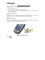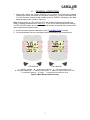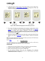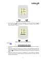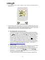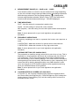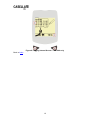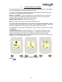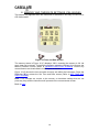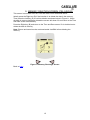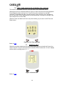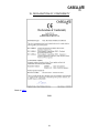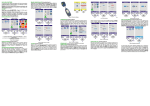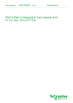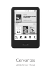
1
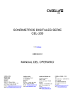
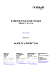
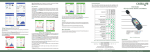
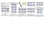
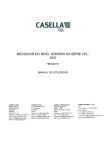
CEL-200 SERIES DIGITAL SOUND
LEVEL METERS
Go to Preface
HB3348-01
OPERATOR’S MANUAL
CASELLA CEL
Regent House
Wolsley Road
Kempston
Bedford
MK42 7JY, U.K.
Phone: +44 (0) 1234 844 100
Fax: +44 (0) 1234 841 490
E-mail:
[email protected]
Web:
www.casellameasurement.com
CASELLA USA
17 Old Nashua Road,
# 15, Amherst
NH 03031
USA
Toll Free: +1 (800) 366
2966
Fax: +1 (603) 672 8053
E-mail:
[email protected]
Web: www.casella USA.com
CASELLA ESPANA S.A.
Polígono Európolis
Calle C, nº4B
28230 Las Rozas - Madrid
Spain
Phone: + 34 91 640 75 19
Fax: + 34 91 636 01 96
E-mail:
online@ casella-es.com
Web: www.casella-es.com
CASELLA CHINA(中国)
地址
北京东城区东方广场W1座911室
邮编: 100738
电话: 0086 10 85183141
传真: 0086 10 85183143
电子邮件:
[email protected]
网址: www.casellachina.cn
PREFACE
Back to Cover
1.
MANUAL CONVENTIONS
This section of the manual details the priority of Warnings, Cautions and Notes that
may apply throughout this manual.
2.
INTRODUCTION
This section of the manual gives a brief overview of the equipment.
PREPARATION FOR USE
3.
This section of the manual describes the first steps to using the CEL-200 Series
Digital Sound Level Meter.
4.
GENERAL OPERATION
This section of the manual describes the basic operating procedures.
CALIBRATION
5.
This section of the manual details the Calibration method.
6.
INSTRUMENT SETTINGS
This section of the manual describes the how to use the Instrument Settings.
7.
CONFIGURATION MENU
This section of the manual describes how to make changes to three specific settings.
TIME AND DATE (CEL-242/246 ONLY)
8.
This screen displays the time and date.
9.
MEMORY DELETION (CEL-242/246 ONLY)
This section details how to delete all loggings from the instrument memory.
10. SET TIME AND DATE (CEL-242/246 ONLY)
This section details how to set the time and date.
11. SWITCH OFF
This section of the manual describes the shut down procedure.
12. EQUIPMENT SPECIFICATION
This section of the manual gives the Specifications and Characteristics for the CEL200 Series Digital Sound Level Meter.
13. SERVICE AND WARRANTY
This section of the manual explains Casella’s after sales policy on the instruments
covered in this manual.
14. ENVIRONMENTAL CONSIDERATIONS
This section of the manual stipulates the environmental policies Casella have
committed to for the manufacture of instruments.
15. DECLARATION OF CONFORMITY
This section shows the declaration of conformity for the CEL-200 series instrument.
2
1.
MANUAL CONVENTIONS
PRIORITY ONE
PERSONAL SAFETY.
When a WARNING is included in the text, the WARNING will always precede the text
it applies to.
WARNING: Indicates personal injury will result if proper precautions are not
followed.
PRIORITY TWO
EQUIPMENT PROTECTION.
A CAUTION will always precede the text it applies to.
CAUTION: Indicates equipment damage can result, if proper precautions are not
taken.
Note(s). Notes usually follow the text to which they apply. Notes can contain advice,
hints, extra information and explanations.
Back to Index
3
2. INTRODUCTION CEL-240, 242, 244 and CEL-246
Congratulations on your purchase of a CEL-200 Series Digital Sound Level Meter,
subsequently referred to as the ‘instrument’. The instrument has been designed to
perform accurate noise measurements through a wide range. It is a completely
digital sound level meter, designed for stable, reliable performance, fully compliant
with international sound level meter standards.
This instruction manual is to help you get the most benefit from your CEL-200
Series Digital Sound Level Meter and to ensure accurate noise measurements.
The CEL-200 Series range comprises of 4 models, the features are summarised in the table
below.
The instrument is illustrated in Figure 1.
4
Figure 1 CEL-200 Series Digital Sound Level Meter
1. Microphone. 2. Power ON / OFF key. 3. Display. 4. Left Key. 5. Right Key.
6. USB PC Output. 7. Auxiliary socket (2.5mm Stereo).
Back to Index
5
3.
PREPARATION FOR USE
PROCEDURE (Refer to Figure 2)
1. Open the Battery Cover.
2. Check the battery compartment is clean and dry.
3. Fit three new AA Alkaline (or NiMH) batteries according to the polarity in the
battery compartment.
4. Close the Battery Cover.
Notes:
If there is evidence of leakage from previously installed batteries, contact Casella
at the address given in Contact Details before using the instrument.
Caution:
Do not mix battery types.
Always fit new batteries when the battery indicator (A) shows battery strength is
low to prevent the instrument switching OFF while in use.
Figure 2 Preparations for Use
Back to Index
6
4.
GENERAL OPERATION
1. Press and release the Power ON/OFF key to switch ON. During the software
initiation the screen will display the firmware version (e.g. V035-05 indicates issue
5 of the firmware) and the serial number (such as 0108121) followed by the Main
Measurement screen. (Refer to Figure 3).
Note: During power-up, CEL-242 and CEL-246 models will display time/date and
memory settings as described in Section 8. If you do not wish to alter these settings
on CEL-242/246 models do not press any keys and the instrument will proceed to the
main measurement shown below.
2. If the instrument requires calibration, refer to CALIBRATION for details.
3. Fit the windshield over the microphone before attempting any measurement.
CEL-240/242
CEL-244/246
A. – Battery Indicator. B. – Over Range Indicator. C. – Sound Pressure Level.
D. Analogue Display Bar. E. Measurement Scale. F. Maximum Sound Pressure Level.
G. Instrument Settings. H. Reset. I. Average Sound Pressure Level.
Figure 3 Main Measurement Screen
7
4. A Bargraph (Refer to Figure 4 [A]) or Time History (Refer to Figure 4 [B]) will be
displayed. Refer to INSTRUMENT SETTINGS to change the Time and
Frequency Weightings, or to change the type of display.
CEL-240/242
CEL-244/246
Figure 4 CEL-200 Series Bargraph and Time History Screens
5. The screen will display the instantaneous and maximum sound pressure levels
along with the relevant Time and Frequency Weighting. Refer to Instrument
Settings to change these settings. Additionally, CEL-244 and CEL-246
instruments will display the average level (Leq or Lavg) since the reset button
was pressed. To reset the maximum sound pressure level and average level,
key.
press and release the
6. When the required measurements have been taken, press and hold the Power
ON/OFF key (Refer to Switch Off) for three seconds to switch the instrument
OFF.
Note: The ‘press and hold for three seconds’ feature prevents the CEL-200 Series
being accidentally switched OFF during use.
Back to Index
5.
CALIBRATION
It is recommended that an acoustic calibration using a CEL-110/2 (or CEL-110/1)
calibrator be performed before and after taking measurements.
PROCEDURE
1. Switch ON the Acoustic Calibrator (Refer to the Calibrator Instruction Manual).
2. Check the Acoustic Calibrator has a 114dB (or 94dB) output.
3. Make sure the instrument is set to the 60-130dB range.
4. Fit the Acoustic Calibrator firmly over the microphone. The instrument
automatically detects a 1kHz tone from a 94 or 114dB Calibrator and enters
Calibration Mode (Refer to Figure 5).
8
Figure 5 Calibration Mode Screen
to perform a calibration, or press the right key (B)
to
5. Press left key (A)
Exit. When calibration is complete, the Calibration Complete screen will be
displayed (Refer to Figure 6).
Figure 6 Calibration Complete Screen
Back to Index
6.
INSTRUMENT SETTINGS
1. The Instrument Settings can be changed from the Measurement screen (Refer to
Figure 7).
2. Press and release the Left key (A). An Arrow (X) will be displayed beside the
Settings key indicating the Settings Menu has been enabled. Note that the reset
symbol
will be replaced by the relevant settings to be changed as described
below.
3. Press and release the Left key (A) repeatedly to cycle through the Settings
screens. Note that the screens displayed will be dependent on which CEL-200
series model purchased.
9
4. Press Right key (B) to make changes to each setting as described below in
sections A - G.
Figure 7 Instrument Settings
5. Current settings will be saved when the instrument is switched OFF. Note that if
no keys are pressed for approximately 5 seconds the CEL-200 Series will exit the
settings screen and return to the normal measurement screen. This will be
evident as the arrow (X) will not be beside the spanner symbol.
A.
RECORDING DATA (CEL-242/246 ONLY)
On the CEL-242 and CEL-246 models the option to record (store) data to
the memory is available. This is the first option available when the settings
key
is pressed. The symbol REC
will be shown and when Right
key (B) is pressed data will be stored in the memory. The CEL-242 will
store 1 second sound pressure levels and the CEL-246 will store levels at a
selectable logging interval as described in section G below. The symbol
will then change to display the current run number e.g. 3
shows it is run
number 3. Pressing the (B) button again will stop the run and store the
results to memory. A maximum of 100 runs can be stored before memory
is full and dB24 software must be used to view the stored measurements. If
the memory is full this settings option will not appear. Please refer to
MEMORY AND TIME/DATE SETTINGS.
B.
DISPLAY TYPE
The Main Display can be toggled between Bargraph and Time History
(Refer to Figure 4 (A) and (B) respectively) by pressing the (B) key.
TIME HISTORY – This setting displays how the maximum sound pressure
has varied over the last 1 minute
or 5 minutes.
e.
BARGRAPH – The Bargraph
well as the sound pressure levels.
displays an analogue bar graph as
To toggle between these three options press and release the Right key (B).
10
C.
MEASUREMENT RANGE (30 – 100dB or 60 – 130dB)
Care should be taken to select the correct measurement range depending
on the noise climate being measured. Make sure the noise being measured is
within the range selected. If the Over Range indicator ( ) is displayed the
incorrect range has been selected. (Refer to Figure 7 [C]). If the noise level is
lower than the selected measurement range ‘--.-dB’ will be displayed.
D.
TIME WEIGHTINGS
FAST - Use this setting for comparatively stable noise.
SLOW - Use this setting for noise with a slow variation.
IMP (Impulse) - Use this setting for noise with rapid variation and impulsive
noise.
Note: If unsure please refer to your local legislation and application
standards.
E.
FREQUENCY WEIGHTINGS
Frequency weightings are used to represent the human ears response to
noise.
A WEIGHTING - Make this selection for general noise measurements.
C WEIGHTING - Make this selection for very high noise levels.
Note: If unsure please refer to your local legislation and application
standards.
F.
AVERAGE SETTING (CEL-244/246 ONLY)
The parameter to measure average noise can be set to Leq or Lavg. This is
dependent on local legislation which sets the exchange rate (Q) to either 3
or 5 respectively. The Q value determines the increase in dB associated
with the doubling of risk to hearing damage. Q=3 means that the increase in
hearing damage risk doubles every 3dB increase in noise, respectively Q=5
means that risk to hearing damage doubles every 5dB increase in noise
level. Use Leq (Q=3) for EU based workplace noise regulations and Lavg
(Q=5) for US/OSHA based noise legislation.
Note: If unsure please refer to your local legislation and application
standards.
G.
LOGGING INTERVAL SCREEN (CEL-246 ONLY)
In Figure 8 (C), the currently selected logging interval is displayed and is
also shown above the Right key (B). Press the Right key (B) to change the
logging interval. Press Left key (A) to exit the settings menu and return to
the measurement screen.
11
Figure 8 Logging Interval Screen – CEL-246 only
Back to Index
12
7.
CONFIGURATION MENU
The Configuration Menu (Refer to Figure 9) is used to make changes to the Display
Contrast, Calibration Level and the Signal Input Source.
To access the Configuration Menu press and hold the Right key when switching the
instrument on (by pressing the Power ON key).
DISPLAY CONTRAST – [Figure 9 Reference X]. Press Right key (B) to adjust the
Contrast. When the contrast is considered ideal press Left key (A) to accept the
changes and progress to the Calibration Level screen.
SIGNAL INPUT SOURCE – [Figure 9 Reference Y].
Note: This option is for the use of acoustic laboratories only.
This screen allows the Signal Input to be routed from the inbuilt microphone, or from
an external signal connected via the auxiliary 2.5mm headphone socket. Press Right
key (B) to toggle between microphone input and alternating current input.
The default Power-Up selection is Microphone Input. Press the Left key (A) to confirm
any changes.
CALIBRATION LEVEL – [Figure 9 Reference Z]. This screen is used to set the
nominal output level of the acoustic calibrator e.g. 114.0dB. Press Right key (B) to
adjust the calibration level. Refer to the calibration certificate for the acoustic
calibrator for the calibrator output level. Press Left key (A) to accept the changes and
progress to the main measurement screen.
Figure 9 Configuration Menu
Back to Index
13
8. MEMORY AND TIME/DATE SETTINGS (CEL-242/246)
This screen only appears when the instrument is switched on and only on CEL-242 or
CEL-246 models.
Figure 10 Time and Date Screen
The memory status in Figure 10 (C) displays 100%, meaning the memory is full. No
more data can be stored. To delete the memory press the Left key (A) to access the
Memory Deletion Screen (Refer to MEMORY DELETION SCREEN). Ensure any
measurements are downloaded via dB24 prior to deletion.
Figure 10 (D) shows the time and date currently set within the instrument. Press the
Right key (B) to access the Set Time and Date screen (Refer to SET TIME AND
DATE SCREEN).
Note: If no changes are require to the memory or time/date settings then do not
press any keys and the instrument will proceed to the measurement screen.
Back to Index
14
9. MEMORY DELETION SCREEN (CEL-242/246)
This screen is accessed from the Time and Date screen described above.
Initially press the Right key (B) if the intention is to delete the data in the memory.
Then press the Left key (A) to confirm deletion as shown below in Figure 11. When
the data in memory has been deleted the screen will show 0% and return to the Time
and Date screen automatically.
Press the Right key (B) and return to the Time and Date screen if it is decided not to
delete the data in memory.
Note: Ensure and saved results are downloaded via dB24 before deleting the
memory.
Figure 11 Memory Discharge Screen
Back to Index
15
10. SET TIME AND DATE SCREEN CEL-242/246
This screen is accessed from the Time and Date screen described above.
When this screen is accessed (Refer to Figure 13) the HH (hours) will be highlighted.
Press Right key (B) to set the hour. Press Left key (A) to advance to the MM
(minutes). Press Right key (B) to set the minutes. Press Left key (A) to advance to
the SS (seconds). Press Right key (B) to set the seconds. Use keys (A and B) in the
same sequence to set the date.
When the time and date have been set press Left key (A) to return to the Time and
Date screen.
Figure 13 Set Time and Date
Back to Index
11.
SWITCH OFF
When the required measurements have been taken, press and hold the Power Key,
refer to Figure 14 (A) for three seconds to switch OFF the instrument. A ‘door’ display
will be shown counting down 3, 2, 1.
Figure 14 Switch OFF
Back to Index
16
12. EQUIPMENT SPECIFICATION
SPECIFICATION
CHARACTERISTICS
STANDARDS
IEC 61672-1 2002-5 (Electro-Acoustics – Sound Level
Meters) Group ‘X’ instruments, Performance Class 2. IEC
60651: 1979 Type 2 .ANSI S1.4 type 2A Specification for
Sound Level Meters.
CEL-244/246 Models: IEC 60804: 2000 Type 2, ANSI
S1.43: 1997 (R2007) Type 2
RANGE:
Display range: 30 -130dB(A) RMS, available in 2 ranges,
30 -100dB and 60 -130dB. Linear operating range 10dB
above noise floor.
RMS FREQUENCY
WEIGHTINGS
A and C filter weightings, satisfying IEC 61672-1: 2002
Class 2, ANSI S1.4 Type 2A.
NOISE F LOOR
Total noise floor typically <33dB(A).
FREQUENCY RESPONSE
Overall frequency response as per IEC 61672-1: 2002
Class 2, ANSI S1.4 Type 2A.
TIME WEIGHTINGS
Fast, Slow and Impulsive according to IEC 61672-1:
2002, ANSI S1.4 Type 2A.
REFERENCE CONDITIONS
o
20 C air temperature, 65% relative humidity, 101.325kPa
atmospheric pressure. Nominal reference level = 114.0dB
at 1kHz. Free field perpendicular incidence.
OPERATING ENVIRONMENTAL CONDITIONS
Humidity
5 to 90% RH in the absence of condensation.
Temperature Range
0 – 40oC.
Pressure
65 to 108kPa.
Effects of Humidity
Less than ±0.5dB over the range 30 to 90% relative
humidity (non-condensing), relative to the value at
reference conditions.
STORAGE ENVIRONMENTAL CONDITIONS
Humidity
0 to 90% RH in the absence of condensation.
Temperature Range
o
-20 to +60 C.
Pressure
65 to 108kPa.
MICROPHONE
Internal electret capsule 10mV/Pa nom +/-3dB within ½”
preamplifier.
CALIBRATION
Auto calibration by application of 1kHz @ 114 or 94dB
calibrator (CEL-110/2 or CEL-110/1). ±1dB calibration
range.
POWER SUPPLY
External DC
5VDC (via US B 5 pin mini B).
Batteries
3x AA, Rechargeable NiMH or Alkaline cells.
17
Battery Life
Typically 35 hours.
Power Consumption
~65mA.
ELECTROMAGNETIC COM PATIBILITY
Instrumentation is designed and tested to comply with the following EMC and ESD
Standards:
IEC 61000-4-2
Testing and Measuring Techniques - Electrostatic
discharge immunity tests.
IEC 61000-4-3
Electrom agnetic compatibility (EMC) - Radiated
electromagnetic field tests.
IEC 61000-4-6
Electrom agnetic compatibility (EMC) - Immunity to
conducted disturbances induced by radio frequency
fields. Tested at 10V/m or greater.
EFFECTS OF AC POWER
FREQUENCY FIELDS
Less than ±0.5dB change in 74dB(A) 925Hz reference
level when subjected to 80A/m AC magnetic field at 50
and 60Hz.
DISPLAY
Resolution
128x128 Mono Graphics LCD.
Update Rate
0.5 seconds update rate.
CONNECTIVITY
USB
USB 2.0 via ‘mini B’ socket. For SPL output (software
required) weighted as per selected frequency and time
weightings.
AUX Socket (2.5mm stereo)
AC output provided for DAT tape / PC wav file recording
or headphone applications. Approx 0.5V RMS Full Scale
Deflection (FSD) ‘A’ weighted output on selected range.
Minimum load impedance 22kΩ. (Optional DC Output via
internal configuration, 0 to 3.3V DC for FSD on selected
range. Output corresponds to selected weighting, 2kΩ
Output impedance).
AC input used for electrical calibration, switched on via
configuration menu.
DATA STORAGE (CEL-242 & CEL-246 Models only)
Memory Size
419,000 Data Points.
Number of Measurements
100.
Maximum Data Points Per
Measurement
65,515.
File Storage Format
.CSV file compatible with MS Excel.
Parameters Stored
CEL-242: 1s sound pressure levels.
CEL-246: 1-10s average value, either Leq or Lavg
dependent on settings.
Back to Index
18
13. SERVICE AND WARRANTY
The manufacturer undertakes to rectify any defect in the instrument directly
attributable to faulty design or assembly and which becomes apparent during the
warranty period. In order to take advantage of this warranty, the instrument must
be returned, carriage paid, to the manufacturer’s factory or accredited agent, where
necessary repairs will be carried out.
The warranty period runs for 24 months from the date of receipt of goods, with
exceptions on certain specialised components supplied by other manufacturers that
may be warranted for shorter or longer periods by their actual manufacturers. In all
such cases, the benefit of these undertakings will be passed on to the user.
CASELLA CEL’s liability is limited to items of their own manufacture, and they do not
accept liability for any loss resulting from the operation or interpretation of the results
from this equipment. To obtain repair under warranty, the instrument should be
packed and returned in it’s original packing or an equivalent either to CASELLA CEL’s
local agent, or in the case of U.K. domestic sales, to the CASELLA CEL Service
Department at Bedford., UK. Please include the following information:
Instrument Type(s), Serial Number(s) and Firmware Version Number(s), Customer
name and address, Contact name and phone number, details of any PC and
Software involved, including Version Number(s), reason for returning the equipment
with a detailed description of the fault and a list of any error messages that m ay
have been displayed.
Back to Index
19
14. ENVIRONMENTAL CONSIDERATIONS
WEEE DIRECTIVE
The WEEE directive aims to raise the level of recycling of electrical and electronic
equipment (EEE) and encourages designers to create products with recycling in
mind. Potentially, a key part of this directive is to make all parties aware and
more responsible for collection, treatment and recovery of WEEE.
CASELLA MEASUREMENT AND WEEE
All Casella products shipped from 13th August 2005 and thereafter will be
marked in accordance with the European standard EN 50419:2005 to indicate
“new EEE waste”. “Historical EEE waste” sold before this date will be handled
according to national legislation in European countries.
RoHS LEGISLATION
The RoHS is a directive from the European Union (EU) and bans the use of
certain substances used in the making of certain electrical and electronic
equipment after July 2006. There are six major substances on the list; lead,
cadmium, mercury, polybrominated biphenyls (PBB's), polybrominated diphenyl
ethers (PBDE's), and hexavalent chromium (Cr (VI)). This directive stems from
the impact these substances have to humans and the environment from both
extraction of raw materials and their eventual disposal as well as occupational
exposure and exposure following disposal. In Europe, over 90% of
electrical/electronic equipment goes into landfill sites which amounts to about 6
million tons of waste every year. Removal of these substances will reduce both
health risks and damage to the environment.
CASELLA MEASUREMENT AND RoHS
Products manufactured by Casella are classified under Category 9, “Monitoring
and control instruments” as per Annex IA of the WEEE directive and as such are
exempt from the requirements of RoHS. As an ‘environmental’ company, Casella
is committed to minimising the full life cycle impact of its products and actions on
the environment. Although Casella products are exempt, we are committed to
working towards the directive and as such are actively involved in a program to
work towards our core product ranges being fully compliant to the demands of the
RoHS directive by 2010. If the scope of the directive changes during this period
we will revise our strategy to ensure full compliance with the directive at all times.
Back to Index
20
15. DECLARATION OF CONFORMITY
Back to Index
END
21