1
PROCESSOR TECHNOLOGY CORPORATION
Sol OPERATING PROCEDURES
7.1
SECTION VII
INTRODUCTION
Information in this section will help you to become familiar
with the operation of your Sol Terminal ComputerTM. Following brief
explanations of the operating controls and the two basic operating
modes, you will put your Sol through some simple operations. This
should sufficiently acquaint you with the keyboard and control
switches so that you will feel at ease with your Sol. In addition,
you will have performed functional tests of all Sol sections except
the parallel data interface.
Detailed descriptions of the control switches are also
provided to allow you to gain greater proficiency in their use. For
the same reason, individual keyboard key descriptions are also given.
They are intended to be used along with the BASIC/5 and SOLOS Users'
Manuals (or if applicable the CONSOL description in Section IX of
this manual).
The balance of this section supplies instructions for 1)
connecting typical peripheral devices to the serial and parallel data
interfaces (J1 and J2), 2) using audio cassette recorders, and 3)
changing the fuse.
7.2
THE OPERATING CONTROLS
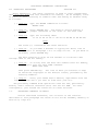
Sol operating controls are identified and their functions
briefly defined in Table 7-1 on Page VII-2. Unless noted otherwise,
the location of each control is shown on the Sol-PC assembly drawing
in Section X, Page X-3.
7.3
7.3.1
BASIC OPERATING MODES
Command Mode
In this mode Sol operates as a stand alone computer under
control of the program (software) contained in the personality module
and additional software that is stored in the Sol, stored either in a
read only memory (ROM) that is plugged into the computer or the Sol
random access memory (RAM). (For a description of the CONSOL and
SOLOS Personality Modules, refer to Section IX in this manual and the
SOLOS Users' Manual respectively.)
With the SOLOS Personality Module installed, the computer is
in the command mode when power is applied to the Sol. Command mode
is a sort of "home base" from which excursions may be made into other
programs. An analysis of three levels of programs will make the
concept of command mode more understandable.
At the lowest level of software are the instructions which the
8080 CPU (central processing unit), the brains of the computer,
VII-1
PROCESSOR TECHNOLOGY CORPORATION
Sol OPERATING PROCEDURES
SECTION VII
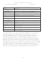
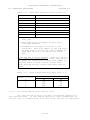
Table 7-1. Sol Operating Controls and Their Functions.
CONTROL
FUNCTION
ON-OFF Switch
Connects and disconnects primary power to Sol.
(See Figure 7-1)
RST (Restart)
Permits manual restart of Sol without turning
Switch, S1-1
power off. (Useful for test purposes.)
BLANK Switch,
Determines if control characters are displayed
S1-3
or not.
POLARITY Switch,
Selects normal (white characters on black
S1-4
background) or reverse video display.
BLINK-SOLID
Selects blinking, nonblinking or no cursor.
Switches, S1-5 & 6
SSW0 – 7
Permits direct data entry to processor.
S2-1 through 8
BAUD RATE Switches,
Sets operating speed of serial data interface
S3-1 through 8
(SDI).
PS & PI Switches
Selects no parity, even parity or odd parity
S4-1 & 5
for SDI.
WLS-1 & 2 Switches,
Selects number of data bits in transmitted
S4-2 & 3
word for SDI.
SBS Switch,
Determines number of stop bits in transmitted
S4-4
word for SDI.
F/!H Switch,
Selects half or full duplex operation for SDI.
S4-6
Keyboard
Data entry, mode selection, command input and
(See Figure 7-4)
cursor control.
can understand and run. All programs must ultimately be reduced to
this basic level to be operated on by the computer. In the case of
the 8080 microprocessor, the program is in an "object code" or
"machine language", since the "machine" or 8080 CPU understands it.
The SOLOS program contained in the personality module is stored in
this machine language form, and the computer can therefore run
directly from this program. Since the SOLOS program is contained in
permanent ROM which is plugged directly into the computer, the SOLOS
program is always available, and is automatically selected whenever
the power switch of the Sol is turned on. There is also provision for
returning at all times to the command mode of SOLOS. From the command
mode other programs may be brought in for various operations or stored
on cassette tape. The contents of the computer's memory may be
displayed or changed. The command mode also performs "housekeeping"
functions such as setting the rate at which data is read from tape, or
the rate at which characters are displayed on the video monitor.
VII-2
PROCESSOR TECHNOLOGY CORPORATION
Sol OPERATING PROCEDURES
SECTION VII
The command mode allows the introduction of the second level
of software. This level includes higher-level language programs such
as BASIC/5 or FOCAL in which complex application programs may be more
easily written. These are called higher level languages because they
permit the user to write programs in a form much closer to human
languages such as English. However, programs written in these
languages must be translated into the more basic machine language
before they can be run. Besides higher level languages, this second
level of software includes programs such as the TREK 80 and GAMEPAC
video games and the ALS-8 program (a software package used for
developing programs), all of which are offered by Processor
Technology Corporation. Through the facilities of the command mode,
these second level programs are transferred (loaded) into memory from
cassette tape or other storage media, and then "executed" (used).
These programs may also exist in ROM or EPROM (erasable programmable
ROM) memory which is plugged into the computer to make them instantly
available like the SOLOS program. All first and second level
programs are stored in the computer as binary object code.
Let us illustrate the concept of the second level of programs
with an example, BASIC/5. Using the "XEQ" command available in the
SOLOS command mode, we load the BASIC/5 program into the computer's
memory from cassette tape. With this command BASIC/5 is ready for
use as soon as the tape has stopped moving. The control of the
computer is now taken over by the BASIC/5 program now in memory, and
SOLOS is no longer in command. All the features of BASIC/5 language
are now available to us, with a new set of commands and rules. Since
the CPU of the computer only understands the machine language of the
first level of software, the BASIC/5 program must translate the
commands and data we enter to this lower level. BASIC/5 does this as
we go. While we are using BASIC/5, we still have access to some of
the commands and features of SOLOS, although they may have a modified
form while we are in BASIC/5. We will load and use BASIC/5 later in
this section.
The third level of software consists of programs written
using the higher order languages of the second level programs. A
program written in BASIC/5 is on this third level. This program only
makes sense to the computer while the computer has BASIC/5 in memory
and control has been transferred to the BASIC/5 program. Third level
programs written in any high level language are often called
"applications programs" since they are usually written in order to
fit a specific application need.
The ALS-8 Program Development System is another second level
program. A program to be developed within ALS-8 would then be a
third-level application program. The ALS-8 also includes an
Assembler which takes a program written on the third level in
"assembly" language, and translates it to object code which the
computer can run. The object code version then resides in memory and
can be run in another operation. For a further discussion, of types
of software see the article "Your Personal Genie" in Appendix VIII of
this manual.
VII-3
PROCESSOR TECHNOLOGY CORPORATION
Sol OPERATING PROCEDURES
7.3.2
SECTION VII
Terminal Mode
Sol operates as a CRT terminal in this mode, capable of sending
keyboard data to an output port and displaying data received at the
serial input port on an external video monitor via the Sol video
display circuitry. When Sol is "hard-wired" to another computer or
connected to a modem, the terminal mode is used for data entry, data
retrieval, inquiry/response and monitoring and control applications.
Capabilities in the terminal mode depend on the personality
module used. Both CONSOL and SOLOS Personality Modules permit
operation as a CRT terminal. CONSOL 1) initializes Sol in the terminal
mode whenever you turn the power on or initiate a system reset, 2)
sends keyboard data to the serial data interface (SDI) only, and 3)
provides simple stand-alone computer capabilities. SOLOS, on the other
hand, 1) enters the terminal mode when given the "TERM" (terminal)
command, 2) sends keyboard data to any output port available with the
"SET 0" (set out) command, and 3) duplicates CONSOL functions while
providing additional capabilities.
7.4
GETTING ACQUAINTED WITH Sol
One of the best ways to get acquainted with your Sol is to use
it. After connecting a cassette recorder and video monitor to your
Sol, you will operate the system in the terminal mode to become
familiar with the keyboard and the functions of the video display
switches. You will then switch to the command mode and perform some of
the basic computer operations.
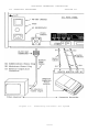
7.4.1
Monitor and Cassette Recorder Connections
The basic Sol system consists of the Sol, a video monitor for
display (e.g., the Processor Technology PT-872 TV-Video Monitor by
Panasonic) and a cassette recorder for external storage (e.g., the
Panasonic Model RQ-413S).
To connect these three system components, you will need the
following cables:
Audio In & Out Cables -- two cables of shielded wire fitted
with miniature phone plugs at both ends.
Motor 1 Cable -- one cable pair, such as speaker wire, fitted
with subminiature phone plugs at both ends. (An identical
cable for Motor 2 is needed if you use two recorders.)
Video Cable -- one RG59/U coaxial cable fitted with a PL259 UHF
male connector on one end and a monitor-compatible connector on
the other.
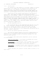
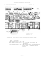
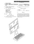
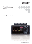
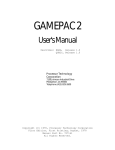
Connect the basic Sol system as follows (refer to Figure 7-1 on
Page VII-6):
VII-4
PROCESSOR TECHNOLOGY CORPORATION
Sol OPERATING PROCEDURES
( ) Step 1.
SECTION VII
Remove top and keyboard covers from Sol.
( ) Step 2. Plug one end of Audio In Cable into Audio IN jack
(J7) on Sol rear panel, and plug other end into MONITOR or
EARPHONE jack on recorder.
( ) Step 3. Plug one end of Audio Out Cable into Audio OUT jack
(J6) on Sol rear panel, and plug other end into AUXILIARY or
MICROPHONE jack on recorder. (The AUXILIARY input is
preferred and recommended over the MICROPHONE input.)
NOTE
If your recorder has only a microphone
jack, remove the I-to-J jumper installed
in Step 69 in Section III and install a
jumper between I and H.
( ) Step 4. Plug one end of Motor I Cable into Motor I jack (J8)
on Sol rear panel, and plug other end into REMOTE jack on
recorder.
( ) Step 5. Connect PL259 UHF connector on Video Cable to video
output connector on Sol rear panel, and connect other end to
video monitor input connector.
( ) Step 6. Make sure monitor, recorder and Sol power switches
are in their OFF position. Then connect AC power cord to AC
receptacle on Sol rear panel and connect Sol, monitor and
recorder to appropriate power source.
7.4.2
Terminal Mode Operation
The following procedure assumes your Sol is equipped with a
SOLOS personality module.
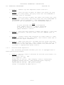
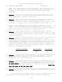
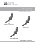
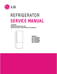
( ) Step 7. Set Sol control switches as follows (see Figure 7-2
on Page VII-7):
RST Switch (S1-1): OFF
S1-2 (spare): OFF
BLANK Switch (S1-3): OFF (display control characters)
POLARITY Switch (S1-4): OFF (reverse video display)
BLINK Switch (S1-5): OFF (solid cursor)
SOLID Switch (S1-6): ON (solid cursor)
(Step 7 continued on Page VII-7.)
VII-5
PROCESSOR TECHNOLOGY CORPORATION
Sol OPERATING PROCEDURES
Figure 7-1.
SECTION VII
Connecting the basic Sol system
VII-6
PROCESSOR TECHNOLOGY CORPORATION
Sol OPERATING PROCEDURES
SECTION VII
1 2 3 4 5 6 7 8
1 2 3 4 5 6
1 2 3 4 5 6 7 8
ON
6 5 4 3 2 1
Figure 7-2.
REAR
OF Sol
FRONT OF Sol
Sol control switch settings for terminal mode.
(Step 7 continued.)
SSW Switches (S2-1 - 8): OFF
BAUD RATE Switches (S3-1 - 8): S3-4 ON, all others OFF
(300 Baud)
SDI Switches (S4-1 - 6):
OFF (selects full duplex operation,
8 data bits, 2 stop bits and no
parity)
VII-7
PROCESSOR TECHNOLOGY CORPORATION
Sol OPERATING PROCEDURES
( ) Step 8.
SECTION VII
Turn Sol and monitor on.
( ) Step 9. If the monitor display raster is out of sync (black
horizontal bar moves slowly down screen, numerous black lines cut
across raster, or both), adjust monitor vertical and horizontal
hold controls for a stable raster.
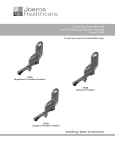
( ) Step 10. You should see a prompt character followed by the cursor
( >n ) in the upper left corner of the screen. If you don't,
adjust VRI and VR2 (see Figure 7-3) to move the prompt character
and cursor onto the screen. (With CONSOL, only the cursor will
appear on the screen.)
NOTE
Use VR1 (horizontal position) and VR2
(vertical position) to center the display
page (16 lines, 64 characters/line) on the
screen.
4- Left
Figure 7-3.
VRI (Horizontal)
Location of positioning adjustments, VRI and VR2.
( ) Step II. Enter terminal mode by 1) pressing UPPER CASE key
to turn the indicator light on (Alphabetic characters are
now entered as upper case, regardless of SHIFT key status,
but dual character keys do respond to SHIFT key.), 2) typing
TERM and 3) pressing RETURN key. (If your Sol is equipped
with CONSOL, it entered terminal mode when you turned the
Sol on.) "TERM" will appear on the screen as you type, and
the cursor will disappear when you press the. RETURN key.
VII-8
PROCESSOR TECHNOLOGY CORPORATION
Sol OPERATING PROCEDURES
SECTION VII
NOTE: All commands must be given in upper case characters in
order to be recognized, and the RETURN key must be pressed after a
command so that SOLOS can execute the command (MODE SELECT
excepted).
( ) Step 12. Set for local operation by pressing LOCAL key to turn
indicator light on. Set for lower case operation by pressing
UPPER CASE again (indicator light out).
( ) Step 13. Press each of the alphanumeric, punctuation and symbol
keys. As each is pressed, the lower case character in the
UNSHIFTED column of Table 7-4 should appear on the screen. Read
Section 7.7 on page VII-17 to become familiar with Table 7-4.
NOTE: If the MODE SELECT key is pressed, SOLOS will return to the
command mode and display a prompt character followed by the
cursor. In this case return to terminal mode by typing "TERM" in
upper case letters, followed by a carriage return.
( ) Step 14. Press SHIFT LOCK key to return keyboard to shifted
operation (indicator light will go out) and repeat Step 13. Each
corresponding upper case character should appear from the SHIFTED
column of Table 7-4.
( ) Step 15. Use the control sequences given in Table 7-4 on Page VII18 to generate the indicated control characters. Control
characters are generated by pressing the CTRL (control) key and,
while holding it depressed, pressing the desired key given in the
first column of the table. As the table shows in the last two
columns, the symbol generated by a control sequence depends on
whether a 6574 or 6575 character generator (U25) is installed in
your Sol. Two examples follow:
CONTROL SEQUENCE
CTRL and I
6574 SYMBOL
à
x
CTRL and 5 or %
6575 SYMBOL
HT
EQ
( ) Step 16. Change video display polarity by setting POLARITY Switch
(SI-4) to ON and observe the effect on the display. It should
change from black characters on a white background to white
characters on a black background.
( ) Step 17. Switch from non-blinking cursor to a blinking cursor by
setting SOLID Switch (SI-6) to OFF and BLINK Switch (SI-5) to ON
in that order. You should see a rectangular solid cursor that
blinks on and off approximately two times per second. Never put
SI-5 and SI-6 ON at the same time.
( ) Step 18. Blank control characters by setting BLANK Switch (SI-3)
to ON. Any control characters generated (refer to Step should not
appear on the screen.
Up to this point, keyboard data has been processed by the CPU,
transmitted out through the serial channel output, looped back
VII-9
PROCESSOR TECHNOLOGY CORPORATION
Sol OPERATING PROCEDURES
SECTION VII
to the serial channel input and then displayed on the video monitor.
You have consequently just "tested" the CPU, serial channel and display
section functions in your Sol.
7.4.3
Command Mode Operation
The following operations assume your Sol is equipped with a
SOLOS personality module.
Using the Cassette Recorder. The following procedure for loading a
program from cassette tape into Sol memory provides a good example of
how to use an audio cassette recorder with Sol. In this example you
will use the BASIC/5 cassette supplied with your Sol.
( ) Step 19.
Set POLARITY (S1-4) and BLANK (S1-3) Switches as desired.
( ) Step 20.
Replace top and keyboard covers.
( ) Step 21. Load BASIC/5 cassette in recorder. If required, fully
rewind tape. (This can be done by disconnecting the REMOTE plug from
the recorder and using the REWIND control on the recorder.) After
rewinding, reconnect REMOTE plug.
( ) Step 22. Set the following recorder controls and indicator, if so
equipped, as indicated:
Transport:
Volume:
Tone:
press STOP control
midrange
top of range (maximum treble)
Tape Counter:
0
( ) Step 23. Press PLAY control on recorder. The tape should not
move. If it does, there is a malfunction in the remote control
circuitry or cabling. (With the Sol off, there should be no continuity
between the REMOTE plug contacts.)
NOTE
The tape head must be clean to reliably read
a tape or write on tape.
( ) Step 24. If needed, press MODE SELECT key on Sol to enter command
mode. (Remember SOLOS initializes in the command mode while CONSOL
initializes in the terminal mode whenever Sol is turned on.) You
should see a prompt character followed by the cursor ( >n ) on the
left of the screen.
VII-10
PROCESSOR TECHNOLOGY CORPORATION
Sol OPERATING PROCEDURES
( ) Step 25.
SECTION VII
Type the XEQ command as follows:
XEQ BASIC
( ) Step 26. Press the RETURN key on Sol. The cursor should disappear
and the tape should advance. The display should not change
otherwise. NOTE: With certain cassette recorders or cassettes
there may be a misreading of the tape when the splice joining the
leader to the tape passes the tape head. In this case an ERROR
message will appear and the tape will stop. To resume tape
"loading", retype the XEQ BASIC command. If further difficulty is
encountered, try different cassette recorder volume settings until
a reliable setting is found.
( ) Step 27. If the tape has loaded successfully, in approximately two
minutes BASIC/5 will display five lines of text ending with:
SOL BASIC 5
READY
( ) Step 28. BASIC/5 is now ready for use. Refer to your BASIC/5
User's Manual. Become familiar with both BASIC/5 and the Sol
keyboard. Try some exercises in BASIC/5.
Dump Operation. The dump operation displays memory data in
hexadecimal on the video monitor. It can also be used with the
appropriate SET command to output memory data to a hard-copy device
(e.g., a printer). As an example, dump the first part of the SOLOS
personality module (C000 through C0E0) as follows:
( ) Step 29. Set UPPER CASE key so that the indicator is on. If you
are still in BASIC/5, type the BASIC/5 command "BYE" at the
beginning of a command line to re-enter SOLOS command mode.
BASIC/5 remains in memory and may be returned to by typing a
command line: "EXEC 0".
( ) Step 30.
Type the DUMP command as follows:
DUMP C000 C0E0
( ) Step 31. Press RETURN key. Lines of 16 bytes of hexadecimal data
will scroll (move) rapidly up the screen until the last address
(C0E0) is displayed. At this point the display will stop
scrolling.
VII-11
PROCESSOR TECHNOLOGY CORPORATION
Sol OPERATING PROCEDURES
SECTION VII
Enter Operation. The enter operation is used to enter hexadecimal
data from the keyboard into available Sol memory. As an example, enter
16 bytes of data, starting at address C900 and ending at address C90F,
as follows:
( ) Step 32.
Type the ENTER command as follows:
ENTER C900
( ) Step 33. Press RETURN key. The monitor should display a
colon (:) prompt character at the start of the next line.
( ) Step 34.
Type the following data:
II 22 33 44 55 66 77 88 99 00 AA BB CC DD EE FF/
NOTE
The slash (/) terminates the enter function.
( ) Step 35. If you made a mistake in typing the above line of
data, refer to Paragraph 7.8.3 on Page VII-25. If you made no
mistakes, press RETURN key.
The data entered in Step 34 now resides in locations C900
through C90F in the Sol memory.
( ) Step 36. To verify that the data did indeed enter Sol memory,
simply give your Sol this DUMP command:
DUMP C900 C90F
Then press RETURN key. The line of data you entered in Step
35 should be displayed on the monitor screen, preceded by the
starting address.
( ) Step 37. Using your SOLOS User's Manual, experiment with the
other commands until you feel at home with your Sol.
The preceding command mode operations used the CPU, personality
module, audio cassette interface (ACI) and the Sol RAM. You have
consequently just tested the functions of these sections.
7.5
OPERATING CONTROLS IN DEPTH
Unless indicated otherwise, the location of the controls
described in this paragraph are shown on the Sol-PC assembly drawing in
Section X, Page X-3.
VII-12
PROCESSOR TECHNOLOGY CORPORATION
Sol OPERATING PROCEDURES
7.5.1
SECTION VII
ON-OFF Switch (See Figure 7-1 on page VII-6.)
Push this switch in to turn your Sol on. In the ON position
the switch remains locked in its "in" position. To turn your Sol off,
push the switch again. This releases the locking mechanism, and the
switch will return to its OFF ("out") position.
7.5.2
Restart (RST) Switch, S1-1
This switch permits you to restart your Sol without turning the
power off. You should normally leave it in its OFF, or run, position.
Set it to ON and then OFF to initialize the Sol circuitry and reset the
CPU program counter to zero. (A manual restart with this switch
performs the same function as turning the power on or pressing a
keyboard generated restart: UPPER CASE key with REPEAT key.)
7.5.3
Control Character Blanking (BLANK) Switch, S1-3
Set this switch to its ON position if you do not want control
characters (see Table 7-4 on Page VII-18) to be displayed on the
screen. In the OFF position, control characters are displayed.
7.5.4
Video Display (POLARITY) Switch, S1-4
If you want a normal video display (white characters on a black
background), set this switch to its ON position. In the OFF position,
black characters will be displayed on a white background (reverse video
display).
7.5.5
Cursor Selection (BLINK, SOLID) Switches, S1-5 & 6
CAUTION
DO NOT SET S1-5 AND S1-6 TO THEIR ON
POSITIONS AT THE SAME TIME. TO DO SO MAY
DAMAGE YOUR Sol.
ON.
If you want the cursor to blink, set S1-6 to OFF and S1-5 to
The cursor will blink on and off about two times per second.
Set S1-5 to OFF and S1-6 to ON if you want a non-blinking
(solid) cursor.
With both S1-5 and S1-6 in their OFF positions, there will be
no cursor display.
7.5.6
Sense (SSW0 - 7) Switches, S2-1 through S2-8
These eight switches are normally left in the OFF position.
They are used to manually enter data into the CPU. (They serve the
same function as the front panel sense switches on the Altair 8800 and
IMSAI 8080.)
VII-13
PROCESSOR TECHNOLOGY CORPORATION
Sol OPERATING PROCEDURES
SECTION VII
S2-1 is the least significant data bit (D100) and S2-8 is the
most significant data bit (DIO7). To pull a DIO bit low (when the
program tests SSW0 - 7), set the switch associated with the bit to ON.
An open (OFF) switch pulls the associated DIO bit high when the program
tests SSW0 - 7.
NOTE
The configuration of SSW0 - 7 is tested
by the CPU only when it executes an
input port FF instruction. Otherwise,
the Sense Switches have no bearing on
Sol operation.
7.5.7
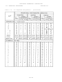
Baud Rate Switches, S3-1 through S3-8
The setting of the Baud Rate Switches determines the operating
speed of the Serial Data Interface (SDI). Assuming you have not
installed any of the K, L and M jumper options, you can select any one
of eight Baud rates. Table 7-2 on page VII-15 defines Baud rate as a
function of S3-1 through S3-8.
CAUTION
DO NOT SET MORE THAN ONE S3 SWITCH TO THE
ON POSITION AT THE SAME TIME. TO DO SO
CAN DAMAGE YOUR Sol.
7.5.8
Parity (PS, PI) Switches, S4-1 & 5
With these two switches you can select no parity, parity, even
parity or odd parity for data handled through the SDI (J1).
Set S4-5 (PI) to its ON position if you want a parity bit.
When OFF, there will be no parity bit. (A stop bit immediately follows
the data if no parity bit is selected.)
S4-1 (PS) selects even or odd parity if S4-5 is ON. It
otherwise has no affect. For even parity, set S4-1 to ON. Set S4-1
OFF for odd parity.
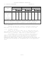
7.5.9
Data Word Length (WLS-I & 2) Switches, S4-2 & 3
Use these two, switches to select the number of bits, excluding
parity, in the transmitted word for the SDI. You have a choice of 5,
6, 7 or 8 bits. Table 7-3 defines word length as a function of S4-2
and S4-3.
7.5.10
Stop Bit Selection (SBS) Switch, S4-4
Set this switch to ON if you want one stop bit transmitted out
of the SDI. In the OFF position, two stop bits are transmitted unless
you have selected a five bit word length. In that case 1.5 stop bits
are transmitted.
VII-14
PROCESSOR TECHNOLOGY CORPORATION
Sol OPERATING PROCEDURES
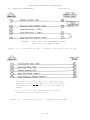
Table 7-2.
SECTION VII
Baud Rate Selection With Switch S3.
BAUD RATE
75
110**
150
300
600
1200
2400
4800***
SWITCH S3 CONFIGURATION*
S3-1
S3-2
S3-3
S3-4
S3-5
S3-6
S3-7
S3-8
ON,
ON,
ON,
ON,
ON,
ON,
ON,
ON,
all
all
all
all
all
all
all
all
others
others
others
others
others
others
others
others
OFF
OFF
OFF
OFF
OFF
OFF
OFF
OFF
*Set no more than one switch to ON at the
same time.
**Rate required by standard 8-level TTY’s
(Teletype Machine).
***Assumes K-to-M jumper on Sol-PC is not
installed. With K-M jumper in and L-M trace
on back side of Sol-PC cut, SDI operates at
9600 Baud when S3-8 is ON and all others
OFF.
NOTE FOR REV D Sol-PC BOARDS: With S3-7 ON and
all others OFF, Baud rate is either 2400 (K-toM jumper not installed) or 4800 (K-M jumper in
and L-M trace on back side of Sol-PC cut).
With S3-8 ON and all others OFF, Baud rate is
9600.
Table 7-3.
Word Length Selection With S4-2 & 3.
WORD LENGTH
(Number of Bits)
5
6
7
8
7.5.11
SWITCH SETTINGS
S4-2
S4-3
ON
ON
ON
OFF
OFF
ON
OFF
OFF
Full/Half Duplex (F/H) Switch, S4-6
Set this switch to ON if you want half duplex operation in
the terminal mode. In half duplex operation, data transmitted out
the SDI (J1) is "looped back" and received by the SDI for subsequent
VII-15
PROCESSOR TECHNOLOGY CORPORATION
Sol OPERATING PROCEDURES
SECTION VII
display on the monitor. Use this type of operation when your Sol works
with an external computer that does not "echo" data back to the Sol.
For full duplex: operation in the terminal mode, set S4-6 to
OFF. Only received data is displayed in full duplex operation. Use
full duplex when Sol's transmitted data need not be displayed. (Note
that transmitted data from the Sol, if echoed back, is displayed as
received data.)
NOTE
If no Baud rate is selected, data will not
be transmitted out of the SDI.
7.5.12
Keyboard
The keyboard is an output device that produces ASCII (American
Standard Code for Information Interchange) encoded data. It is
hardwired to an input port on the Sol and is used for data entry.
ASCII data is interpreted by the Sol as data and/or commands as
determined by the current system monitor program. The monitor program
may be in the personality module, ALS-8, Sol RAM memory or some memory.
7.6
THE KEYBOARD, GENERAL DESCRIPTION
The Sol Terminal Computer has ASCII 96-character keyboard. Its
key arrangment conforms with the QWERTY (standard typewriter) format.
As shown in the photo on page X-26, there are also 12 control keys
(including five basic cursor controls) and seven special function keys.
A 15-key arithmetic pad, available as an option on the Sol-10, is
provided as standard equipment on the Sol-20.
7.6.1
Operating Features
The Sol keyboard features N-key rollover. That is, several
keys can be pressed at the same time without loss of characters or
commands. Key entries, however, are in the order of actual key
closures. (The keyboard circuitry includes a scanning circuit that
prevents simultaneous key operation.)
7.6.2
Keyboard Indicators
Three keys (SHIFT LOCK, UPPER CASE and LOCAL) have indicator
lights to indicate keyboard/terminal status. When any of these keys is
pressed to turn an indicator light on, the light remains on after the
key is released to show that the status persists. Pressing the key
again turns the light out to indicate the change in status.
VII-16
PROCESSOR TECHNOLOGY CORPORATION
Sol OPERATING PROCEDURES
7.7
SECTION VII
INDIVIDUAL KEY DESCRIPTIONS
The exact function of most keys on the Sol keyboard is
determined by the software used (e.g., the personality module). Others
have predefined functions that are common to the CONSOL and SOLOS
Personality Modules. (Note that any key that generates a code can be
redefined by a program to perform a specific funstion.)
The code
generated by each key on the keyboard and the corresponding character,
or symbol, produced by the Sol's character generator (U25) are given in
Table 7-4 on Pages VII-18 through VII-21.
Table 7-4 has two main headings: 1) KEY which identifies the
keys on the Sol keyboard and 2) HEXADECIMAL CODE/CHARACTER GENERATION
which specifies for each key the hexadecimal code generated by the
keyboard and the symbol produced by the Sol's character generator. The
second heading is divided into three major categories: UNSHIFTED,
SHIFTED and CONTROL. UNSHIFTED defines the results when operating the
keys unshifted (lower case), SHIFTED provides the same information when
they are operated shifted (upper case), and CONTROL defines the results
of control sequences (refer to Paragraph 7.7.7 on Page VII-22). Within
each of these three categories you will find the hexadecimal code
generated and the symbol displayed in response to that code by either
of the two possible character generators that can be supplied with your
Sol, the 6574 and 6575. Some keys move the cursor without displaying a
new character.
Looking at the "W" entry on Page VII-18 and reading across the
table, we see that:
1.
Pressing "W" unshifted would generate the code 77 and
either character generator (6574 or 6575) produces a lower case "W"
(w). Do not actually press the keys at this point.
2.
Pressing "W" shifted would generate the code 57 and either
character generator would produce an upper case "W" (W).
3.
Pressing CTRL (control) and "W", whether shifted or
unshifted, generates the code 17 which causes the 6574 to produce the
graphic symbol “-|”) for the ASCII "end of transmission block" control
character and the 6575 to produce a two-character mnemonic (EB) for
that same control character.
In the following paragraphs, each key function is described in
terms of its role in the terminal mode only and assumes the control
character display option is enabled and the LOCAL indicator light is
on. Many key functions differ from these descriptions in SOLOS command
modes BASIC/5, ALS-8, etc. As an aid to learning each key location, we
suggest that you keep the keyboard photo, X-26, in view as you study
these functions.
7.7.1
Alphanumeric-Punctuation-Symbol Keys
These keys enter the applicable character into the Sol.
VII-17
PROCESSOR TECHNOLOGY CORPORATION
Sol OPERATING PROCEDURES
Table 7-4.
SECTION VII
Sol Keyboard Assignments.
VII-18
PROCESSOR TECHNOLOGY CORPORATION
Sol OPERATING PROCEDURES
Table 7-4.
SECTION VII
Sol Keyboard Assignments.
(Continued)
*See notes at end of this table. Page VII-21.
VII-19
PROCESSOR TECHNOLOGY CORPORATION
Sol OPERATING PROCEDURES
Table 7-4.
SECTION VII
Sol Keyboard Assignments.
(Continued)
VII-20
PROCESSOR TECHNOLOGY CORPORATION
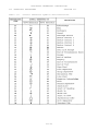
Sol OPERATING PROCEDURES
KEY#
SPECIAL KEYS
LOAD
MODE SELECT
↑
←
→
↓
HOME CURSOR
CLEAR
SECTION VII
HEXADECIMAL CODE/CHARACTER GENERATION
UNSHIFTED
SHIFTED
CONTROL
Symbol
Symbol
Symbol
HEX.
HEX.
HEX.
Displayed*
Displayed*
Displayed*
Code
Code
Code
6574 6575
6574 6575
6574 6575
8C
80
97
81
93
9A
8E
8B
None
None
None
None
None
None
None
None
FF
None
None
None
None
None
None
None
8C
80
97
81
93
9A
8E
8B
None
None
None
None
None
None
None
None
FF
None
None
None
None
None
None
None
8C
80
97
81
93
9A
8E
8B
None
None
None
None
None
None
None
None
FF
None
None
None
None
None
None
None
#Vertical line between characters indicates dual character key.
*Character generated is displayable and transmittable. “None” means no
code is generated or no symbol is displayed. Return is defined in
Section 7.7.11, and line feed in Section 7.7.12, on page VII-24.
7.7.2
Space Bar
Pressing the Space Bar, shifted or unshifted, generates the
ASCII space code (20) and moves the cursor one space to the right.
7.7.3
Arithmetic Pad Keys
Except for the division symbol key (), these keys enter the
applicable character into the Sol. The division symbol key enters a
forward slash (/) character. SHIFT does not affect these keys.
The arithmetic pad is useful for entering large amounts of
numerical data. Each key in the pad duplicates its corresponding
numeric, period (decimal point), dash (minus), plus (addition),
asterisk (multiplication) and forward slash (division) key in the
"typewriter" group of keys. That is, pressing one of the pad keys does
the same thing as pressing its corresponding key in the "type-writer"
group.
VII-21
PROCESSOR TECHNOLOGY CORPORATION
Sol OPERATING PROCEDURES
7.7.4
SECTION VII
ESCAPE Key
Pressing ESCAPE, shifted or unshifted, generates the ASCII
escape character (1B). The character is displayed.
7.7.5
BREAK Key
Pressing BREAK, shifted or unshifted, forces the SDI output
line to a space level for as long as the key is depressed. No
character is displayed. (Some communications systems use this
feature.)
7.7.6
TAB Key
Pressing TAB, shifted or unshifted, generates the ASCII
horizontal tab character (09). The character is displayed.
7.7.7
Control (CTRL) Key
CTRL, shifted or unshifted, is used with alphanumeric,
punctuation and symbol keys to initiate functions or generate the
characters defined in Table 7-4. Table 7-5 defines the ASCII control
characters. The characters in Table 7-5 are not always displayed on
the video monitor.
A control sequence (e.g., CTRL plus J, which produces ASCII
line feed) requires that CTRL be pressed first and held down while the
other key or keys are pressed in sequence.
7.7.8
SHIFT Key and SHIFT LOCK Key/Indicator
The SHIFT key generates no code and is thus not displayed. It
is interpreted as a direct internal operation, and when pressed
specifically shifts the keyboard from lower case to upper case and from
the lower to upper character on dual character keys as on a typewriter.
The keyboard remains in upper case as long as SHIFT is held down.
Pressing SHIFT LOCK to turn the indicator light on
electronically locks the SHIFT key in the upper case position. Again,
no code is generated and no character is displayed. Pressing SHIFT
returns the keyboard to lower case and causes the SHIFT LOCK indicator
light to go out.
7.7.9
UPPER CASE Key/Indicator
Pressing this key, shifted or unshifted, to turn the indicator
light on activates the upper case keyboard function so that all
alphabetic characters entered from the keyboard, regardless of SHIFT
key status, are transmitted as upper case characters.
(Dual character
keys, however, do respond to the SHIFT key.) With the indicator light
on, the Sol keyboard essentially simulates a teletype (TTY) keyboard.
Pressing UPPER CASE to turn the indicator light off returns the
keyboard to normal SHIFT key operation.
VII-22
PROCESSOR TECHNOLOGY CORPORATION
Sol OPERATING PROCEDURES
Table 7-5.
SECTION VII
Control Character Symbols and Definitions.
VII-23
PROCESSOR TECHNOLOGY CORPORATION
Sol OPERATING PROCEDURES
7.7.10
SECTION VII
LOCAL Key/Indicator
The LOCAL key internally connects the SDI output to the SDI
input and disables serial transmission. No character is displayed.
Pressing LOCAL, shifted or unshifted, to turn the indicator light on
sets Sol for local operation. Keyboard entries are not transmitted,
but they are "looped back" to the SDI input for display. That is, Sol
is not on "line". Pressing LOCAL to turn the light off ends local
operation. This corresponds to the local/line operation of a TTY.
7.7.11
RETURN Key
Pressing RETURN, shifted or unshifted, generates the ASCII
carriage return character (0D), which is not displayed, and moves the
cursor to the start of the line on which it resided prior to RETURN
being depressed. (This is the same action as a TTY carriage return.)
RETURN also erases all data in the line to the right of the cursor.
7.7.12
LINE FEED Key
Pressing LINE FEED, shifted or unshifted, generates the ASCII
line feed character (0A), which is not displayed, and moves the cursor
vertically downward one line. (This is the same action as a TTY line
feed.) Line feed action does not erase any data in the line to the
right of the cursor.
7.7.13
LOAD Key
The LOAD key character is displayed, but the key is nonfunctional with CONSOL and SOLOS. The code generated by this key is
8C, and it may be used by a program to meet a specific need.
7.7.14
REPEAT Key
The REPEAT key generates no character and is consequently not
displayed. Pressing REPEAT, shifted or unshifted, and another key at
the same time causes the other key to repeat at an approximate rate of
15 times per second as long as both keys are held down. Pressing
REPEAT at the same time as UPPER CASE performs a restart. See Section
7.5.2 on page VII-13.
7.7.15
MODE SELECT Key
Pressing this key, shifted or unshifted, generates the code 80
and causes Sol to enter the command mode.
7.7.16
CLEAR Key
Pressing CLEAR, shifted or unshifted, erases the entire screen
and moves the cursor to its "home" position (upper left corner of the
screen).
VII-24
PROCESSOR TECHNOLOGY CORPORATION
Sol OPERATING PROCEDURES
7.7.17
SECTION VII
Cursor Control (HOME CURSOR and Arrows) Keys
Five keys control basic cursor movement. They are HOME CURSOR
and the four keys with arrows. None are affected by SHIFT status, and
none are displayed or transmitted.
Pressing HOME CURSOR moves the cursor to its home position--the
first character position in the upper left corner of the screen.
To move the cursor up, down, left or right, press the
applicable "arrow" key. Each time you press a key the cursor moves one
unit in the direction you wish--one space horizontally or one line
vertically. These keys may be used with REPEAT. The cursor will not
move across any margin of the screen with these four keys.
7.8
BASIC OPERATIONS
7.8.1
Switching From Terminal To Command Mode
To switch from terminal to command mode, simply press the MODE
SELECT key. Sol enters the command mode, issues a prompt character
( > ) and waits for a command input.
7.8.2
Switching From Command To Terminal Mode
To switch from command to terminal mode, press UPPER CASE, TERM
and RETURN in that order. Sol enters the terminal mode and all
keyboard data will be sent to the SDI output and ail data received
(including "looped back" data) will appear on the screen.
7.8.3
Entering Commands In The Command Mode
The various commands for CONSOL and SOLOS are described in
Section IX of this manual and the SOLOS Users' Manual respectively.
You can place more than one command on the screen. For each
command, use the arrowed cursor control keys to position the cursor at
the start of a new line and begin the new command line with a prompt
character ( > ).
A command is executed when you press the RETURN key, and all
characters on the line to the left of the cursor are interpreted as the
command. This means that if more than one command line is on the
screen, you can execute any one of them as follows:
position the
cursor with the arrowed cursor control keys to the right of the desired
command and press RETURN.
Should you make a mistake when entering a command, there are
two ways to correct it:
(Paragraph 7.8.3 continued on Page VII-26.)
VII-25
PROCESSOR TECHNOLOGY CORPORATION
Sol OPERATING PROCEDURES
7.8.4
SECTION VII
1.
If you see the error immediately (the error is to the
immediate left of the cursor), press the DEL key
(unshifted) to erase the mistake. Then make the
correction.
2.
If the error is more than one character position to the
left of the cursor, use the arrowed cursor control keys
to position the cursor over the mistake.
Then make the
correction
Keyboard Restart
To perform a keyboard restart, press the UPPER CASE and REPEAT
keys at the same time. This key combination performs the same function
as a power on initialization or setting the RST switch to ON. Use the
keyboard restart to return to SOLOS/CONSOL from 1) a program which does
not recognize the MODE SELECT key or 2) a program that is stuck in an
endless loop.
7.9
Sol-PERIPHERAL INTERFACING
7.9.1
Audio Cassette Recorders
Your Sol is capable of controlling one or two recorders. The
interconnect requirements for one recorder were previously covered in
Paragraph 7.4.1 in this section.
Since the Sol has only one audio input and one audio output
jack, however, the interconnect requirements for two recorders are
somewhat different than for one.
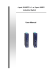
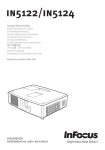
You will need two "Y" adapters, one to feed the single Sol
audio output to the AUXILIARY input of two recorders and the other to
feed the MONITOR output of two recorders to the single Sol audio input.
(If you intend to use the Audio In and Out cables described in
Paragraph 7.4.1 in this section, miniature phone jack-to-two miniature
phone plug adapters are required.) Since the recorder outputs are most
likely unbalanced, we also suggest that you incorporate 1000 ohm
resistors in the MONITOR adapter as shown in Figure 7-5 on Page VII-29.
Figure 7-5 also illustrates, in schematic form, how to connect two
recorders to your Sol.
When using two recorders you may read or write to both under
program control as well as read one tape while writing on the other.
If you intend to read one tape while writing on the other, however, you
may have to disconnect the MONITOR plug from the write unit, with the
need for disconnect being determined by the recorder design. The
MONITOR disconnect must be made if the recorder has a
VII-26
PROCESSOR TECHNOLOGY CORPORATION
Sol OPERATING PROCEDURES
SECTION VII
"monitor" output in the record mode.
do, for example.)
(Panasonic RQ-413S and RQ-309DS
NOTE 1
Recorders on which the "monitor" jack is
labeled MONITOR usually provide a monitor
output in the record mode. If the jack
is labeled EAR or EARPHONE, the recorder
usually does not provide a monitor output
in the record mode.
NOTE 2
To determine if your recorder provides a
monitor output in the record mode, install
a blank tape, plug earphone into "monitor
jack and microphone into MICROPHONE jack,
set recorder controls to record, and speak
into microphone while listening with the
earphone. If you hear yourself through
the earphone, your recorder does provide a
monitor output in the record mode.
Write Operations. Other than placing the recorder(s) in the
record mode, loading the cassette(s) and making sure that the head(s)
is on tape (not leader), no manual operations are needed to write on
tape.
In the case of two recorders, however. Unit 1 and 2 must be
specified in the SAVE command in order to select the desired recorder.
A default selects Unit 1. Refer to your SOLOS Users' Manual for
instructions on how to use tape commands.
Read Operations. In order to read a specific file on tape, you
must start the tape at least two seconds ahead of that file. This
delay allows the Sol audio cassette interface circuitry and the
recorder playback electronics to stabilize after power is turned on.
Since all file searches are in the forward direction, the simplest
approach is to fully rewind the cassette(s) before a read operation
unless you know that the file of interest is advanced at least two
seconds. (See Paragraph 7.4.3, Step 21 for instructions on how to
rewind the tape.)
For a read operation, proceed as follows:
1.
Load cassette(s) as just described.
2.
If only one recorder is used, set its volume control
at midrange. With two recorders, set both volume
controls at their high end.
VII-27
PROCESSOR TECHNOLOGY CORPORATION
Sol OPERATING PROCEDURES
Sol
CONNECTIONS
(J6)
Audio
OUT
SECTION VII
RECORDER
CONNECTIONS
CABLING
(A)
Shielded Cable
(A)
R1
(J7)
Audio
IN
AUXILIARY
Input
(A) (Unit 1)
(A)
AUXILIARY
Input
(A) (Unit 2)
MONITOR
(Unit 1)
(A)
MONITOR
(Unit 2)
R2
(J8) (B)
Motor
1
(J9) (B)
(B)
Speaker Wire
(B)
Motor
2
REMOTE
(Unit 1)
REMOTE
(Unit 2)
(A) Miniature Phone Plug
(B) Subminiature Phone Plug
R1 = R2 = 1000 ohms, 1/4 watt
Figure 7-5.
7.9.2
Connecting Sol to two cassette recorders
3.
Set recorder(s) tone control(s) at the top of the range
(maximum treble).
4.
Set PLAY control(s) for playback mode.
5.
Give Sol the GET or "GET, then Execute" command as
appropriate. (Refer to your SOLOS Users' Manual for
instructions on how to use tape commands.)
Serial Data Interface (SDI)
The Sol Serial Data Interface (J1) is capable of driving an RS232 device, such as a modem, or a current loop device, such as the
ASR33 TTY.
S3 (Baud Rate) and S4 (Parity, Word Length, Stop Bits and
Full/Half Duplex) are used to select the various serial interface
options as described in Paragraphs 7.5.7 through 7.5.11 in this
section.
VII-28
PROCESSOR TECHNOLOGY CORPORATION
Sol OPERATING PROCEDURES
SECTION VII
Set S3 switches to select the Baud rate required by the modem
or current loop device. (Standard 8-level TTY's operate at 110 Baud,
S3-2 ON and all other S3 switches OFF.) For standard 8-level TTY's and
most modems, set all S4 switches OFF. (This selects eight data bits,
two stop bits, no parity bit and full duplex operation for the SDI.
Figures 7-6 and 7-7 show examples of current loop and modem
interconnections to the Sol SDI connector (Jl). The ASR33 TTY is used
to illustrate a current loop interconnect, and the Bell 103 modem is
used to illustrate a modem interconnect.
When operating in the terminal mode and full duplex. Sol
keyboard data is transmitted out on Pin 2 of Jl and date received on
Pin 3 of Jl is displayed on the video monitor. In the command mode,
SOLOS set in and out commands can be used to channel output data and
input data through the SDI. (Refer to your SOLOS Users' Manual for
instructions on how to use the set commands.)
In either mode, the LOCAL key directly controls the SDI. With
the LOCAL indicator light on, received data is ignored and keyboard
data is not transmitted. It is, however, looped back for display on
the video monitor. With the LOCAL light off, received data is
displayed and keyboard data is transmitted but not displayed unless it
is echoed back.
7.9.3
Parallel Data Interface (PDI)
The Sol Parallel Data Interface (J2) is used to drive parallel
devices such as paper tape readers/punches and line printers. It
provides eight output data lines, eight input data lines, four
handshaking signals and three control signals. The latter allow up to
four devices to share the PDI connector.
(See Appendix VII for J2
pinouts.)
The port address for parallel input and output data is FD
(hexadecimal), and the control port address for the PDI is FA
(hexadecimal). PXDR is available at bit 2 of port FA. When this bit
is set to 0, the external device is ready to receive a byte of data.
PDR is available at bit I of port FA, with 0 indicating the external
device is ready to send a byte of data. Parallel Unit Select (PUS) is
controlled by bit 4 of port FA. The input and output enable lines are
available for tri-stating an external two-way data bus.
Use of the three control signals is optional and is unnecessary
when only one device is connected to the PDI connector.
(Paragraph 7.9.3 continued on Page 31.)
VII-29
PROCESSOR TECHNOLOGY CORPORATION
Sol OPERATING PROCEDURES
CAUTION:
Figure 7-6.
SECTION VII
PINS 1 AND 2 ON TTY BARRIER STRIP
CARRY 120 V ac LINE VOLTAGE.
Connecting Sol SDI to current loop device such as TTY.
*Available at bit 1 of port F8. Terminal mode
software (SOLOS et al) does not use this signal
and transmits data whether or not the modem is
ready.
**Sol is wired so that DTR indicates a ready
condition whenever power is on.
Figure 7-7.
Connecting Sol SDI to communications modem.
VII-30
PROCESSOR TECHNOLOGY CORPORATION
Sol OPERATING PROCEDURES
SECTION VII
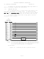
In Figure 7-8, the Oliver OP80 Manual Paper Tape Reader is
used to illustrate a typical PDI interconnect.
7.10
CHANGING THE FUSE
Sol is protected with a 3.0 amp Slo-Blo fuse housed on the
rear panel (see Figure 7-1 on Page VII-6). To remove the fuse,
turn Sol off, disconnect power cord, turn fuse post cap one quarter
turn counterclockwise, pull straight out and remove fuse from cap.
To install a fuse, insert fuse in cap, push in and turn
one-quarter turn clockwise.
(J2)
Sol PDI
CONNECTOR
Rev D* Rev E*
ID0
1
ID1
16
ID2
2
ID3
15
ID4
3
ID5
14
ID6
4
ID7
13
IAK
5
DR
6
-
2
POWER
SUPPLY
+
8
2
NOTE:
9
+5 V dc is not available at J2. The use of an external
+5 V dc power supply with its ground connected to Pin 1
of J2 (Sol chassis ground) is recommended.
*Sol-PC Board
Figure 7-8.
Connecting Sol PDI to parallel device.
VII-31