1
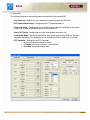
OPERATOR’S
MANUAL
English version 1.0
DHU500 SERIES
MPEG4 Networkable DVR
Copyright „ 2007 Digimerge Technologies Inc.
Thank You
PREFACE
Thank
Thank you for purchasing the DHU500 Series DVR. Digimerge is committed to
providing our customers with a high quality, reliable security product.
The DHU500 Series line of Pentaplex Network DVR’s offer a full-featured Networkable
video recording solution. Record in Real Time with 120 fps recording capability.
Images can be easily transferred using the built in CDRW optical drive or USB flash
drive. The system can be viewed and controlled over the internet from a remote
location with a password protected browser-based application. Easy access via the
Free Digimerge DDNS Service is included.
To learn more about this DHU500 Series DVR, and to learn about our complete range
of accessory products, please visit our website at:
http://www.digimerge.com
CAUTION
RISK OF ELECTRIC SHOCK
DO NOT OPEN
CAUTION: TO REDUCE THE RISK OF ELECTRIC SHOCK
DO NOT REMOVE COVER (OR BACK).
NO USER SERVICEABLE PARTS INSIDE.
REFER SERVICING TO A QUALIFIED SERVICE PERSONNEL
The lightning flash with arrowhead symbol, within an
equilateral triangle, is intended to alert the user to the
presence of uninsulated “dangerous voltage” within the
product’s enclosure that may be of sufficient magnitude
to constitute a risk of electric shock to persons.
The exclamation point within an equilateral triangle is
intended to alert the user to the presence of important
operating and maintenance (servicing) instructions in
the literature accompanying the appliance.
WARNING: TO PREVENT FIRE OR SHOCK HAZARD,
DO NOT EXPOSE THIS UNIT TO RAIN OR MOISTURE.
CAUTION: TO PREVENT ELECTRIC SHOCK, MATCH WIDE BLADE
OF PLUG TO WIDE SLOT, FULLY INSERT.
ii
OPERATORS MANUAL | Copyright © 2006 Digimerge Technologies Inc.
Important Safeguards
PREFACE
Important Safeguards
In addition to the careful attention devoted to quality standards in the manufacture process of your video
product, safety is a major factor in the design of every instrument. However, safety is your responsibility too.
This sheet lists important information that will help to assure your enjoyment and proper use of the video
product and accessory equipment. Please read them carefully before operating and using your video product.
Installation
1. Read and Follow Instructions - All the safety and
operating instructions should be read before the
video product is operated. Follow all operating
instructions.
2. Retain Instructions - The safety and operating
instructions should be retained for future reference.
3. Heed Warnings - Comply with all warnings on the
video product and in the operating instructions.
4. Polarization - Do not defeat the safety purpose of
the polarized or grounding-type plug.
A polarized plug has two blades with
one wider than the other.
A grounding type plug has two blades
and a third grounding prong.
The wide blade or the third prong are
provided for your safety.
If the provided plug does not fit into
your outlet, consult an electrician for
replacement of the obsolete outlet
5. Power Sources - This video product should be
operated only from the type of power source
indicated on the marking label. If you are not sure of
the type of power supply to your location, consult
your video dealer or local power company. For video
products intended to operate from battery power, or
other sources, refer to the operating instructions.
6. Overloading - Do not overload wall outlets of
extension cords as this can result in the risk of fire
or electric shock. Overloaded AC outlets, extension
cords, frayed power cords, damaged or cracked wire
insulation, and broken plugs are dangerous. They
may result in a shock or fire hazard. Periodically
examine the cord, and if its appearance indicates
damage or deteriorated insulation, have it replaced
by your service technician.
8.
Ventilation - Slots and openings in the case are
provided for ventilation to ensure reliable operation
of the video product and to protect it from
overheating. These openings must not be blocked
or covered. The openings should never be blocked
by placing the video equipment on a bed, sofa, rug,
or other similar surface. This video product should
never be placed near or over a radiator or heat
register. This video product should not be placed in
a built-in installation such as a bookcase or rack
unless proper ventilation is provided or the video
product manufacturer’s instructions have been
followed.
9. Attachments - Do not use attachments unless
recommended by the video product manufacturer as
they may cause a hazard.
10. Water and Moisture - Do not use this video product
near water. For example, near a bath tub, wash bowl,
kitchen sink or laundry tub, in a wet basement, near
a swimming pool and the like.
Caution: Maintain electrical safety. Powerline
operated equipment or accessories connected to
this unit should bear the UL listing mark of CSA
certification mark on the accessory itself and should
not be modified so as to defeat the safety features.
This will help avoid any potential hazard from
electrical shock or fire. If in doubt, contact qualified
service personnel.
11. Accessories - Do not place this video equipment
on an unstable cart, stand, tripod, or table. The video
equipment may fall, causing serious
damage to the video product. Use
this video product only with a cart,
stand, tripod, bracket, or table
recommended
by
the
manufacturer or sold with the video
product. Any mounting of the product
should follow the manufacturer’s
instructions and use a mounting accessory
recommended by the manufacturer.
7. Power-Cord Protection - Power supply cords should
be routed so that they are not likely to be walked on
or pinched by items placed upon or against them,
paying particular attention to cords at plugs,
convenience receptacles, and the point where they
exit from the video product.
Revision 1.0
iii
iii
Important Safeguards
PREFACE
Service
Use
13. Servicing - Do not attempt to service this video
equipment yourself as opening or removing covers
may expose you to dangerous voltage or other
hazards. Refer all servicing to qualified service
personnel.
19. Cleaning - Unplug the video product from the wall
outlet before cleaning. Do not use liquid cleaners or
aerosol cleaners. Use a damp cloth for cleaning.
14. Conditions Requiring Service - Unplug this video
product from the wall outlet and refer servicing to
qualified service personnel under the following
conditions.
A. When the power supply cord or plug is
damaged.
B. If liquid has been spilled or objects have fallen
into the video product.
C. If the video product has been exposed to rain
or water.
D. If the video product does not operate normally
by following the operating instructions. Adjust
only those controls that are covered by the
operating instructions. Improper adjustment of
other controls may result in damage and will often
require extensive work by a qualified technician
to restore the video product to its normal
operation.
20. Product and Cart Combination - Video and cart
combination should be moved with care. Quick
stops, excessive force, and uneven surfaces may
cause the video product and car combination to
overturn.
21. Object and Liquid Entry - Never push objects for
any kind into this video product through openings as
they may touch dangerous voltage points or
“short-out” parts that could result in a fire or electric
shock. Never spill liquid of any kind on the video
product.
22. Lightning - For added protection for this video
product during a lightning storm, or when it is left
unattended and unused for long periods of time,
unplug it from the wall outlet and disconnect the
antenna or cable system. This will prevent damage
to the video product due to lightning and power line
surges.
E. If the video product has been dropped or the
cabinet has been damaged.
F. When the video product exhibits a distinct
change in performance. This indicates a need for
service.
15. Replacement Parts - When replacement parts are
required, have the service technician verify that the
replacements used have the same safety
characteristics as the original parts. Use of
replacements specified by the video product
manufacturer can prevent fire, electric shock or other
hazards.
16. Safety Check - Upon completion of any service or
repairs to this video product, ask the service
technician to perform safety checks recommended
by the manufacturer to determine that the video
product is in safe operating condition.
17. Wall or Ceiling Mounting - The cameras provided
with this system should be mounted to a wall or
ceiling only as instructed in this guide, using the
provided mounting brackets.
18. Heat - The product should be situated away from
heat sources such as radiators, heat registers,
stoves, or other products (including amplifiers) that
produce heat.
iv
OPERATORS MANUAL | Copyright © 2006 Digimerge Technologies Inc.
General Precautions
PREFACE
NOTE
This equipment has been certified and found to comply with the limits regulated by FCC, EMC, and LVD. Therefore, it
is designated to provide reasonable protection against interference and will not cause interference with other appliance
usage.
However, it is imperative that the user follows this manuals guidelines to avoid improper usage which may result in
damage to the unit, electrical shock and fire hazard injury
In order to improve the feature functions and quality of this product, the specifications are subject to change without
notice from time to time.
FCC CLASS B NOTICE
Note:
This equipment has been tested and found to comply with the limits for a Class B digital device, pursuant to Part
15 of the FCC Rules. These limits are designed to provide reasonable protection against harmful interference in
a residential installation. This equipment generates, uses, and can radiate radio frequency energy and, if not installed and used in accordance with the instruction, may cause harmful interference to radio communications.
However, there is no guarantee that interference will not occur in a particular installation. If this equipment does
cause harmful interference to radio or television reception (which can be determined by turning the equipment on
and off), the user is encouraged to try to correct the interference by one or more of the following measures:
z
z
z
z
Reorient or relocate the receiving antenna
Increase the separation between the equipment and receiver
Connect the equipment into an outlet on a circuit different from that to which the receiver is
connected
Consult the dealer or an experienced radio or television technician for assistance
General Precautions
1. All warnings and instructions of this manual should be followed
2. Remove the plug from the outlet before cleaning. Do not use liquid aerosol detergents. Use a water dampened cloth
for cleaning
3. Do not use this unit in humid or wet places
4. Keep enough space around the unit for ventilation. Slots and openings in the storage cabinet should not be blocked
5. During lightning storms, or when the unit is not used for a long time, disconnect the power supply, antenna, and cables
to protect the unit from electrical surge
DIGIMERGE TECHNOLOGIES INC.
http://www.digimerge.com
Revision 1.0
v
v
Table of Contents
TOC
Table of Contents
Section 1 - Location and Control
DHU500 Series - Front .................................................................... 8
DHU500 Series - Back ................................................................... 10
Section 2 - Remote Control..................................................................... 14
Section 3 - Operating the DVR ............................................................... 15
Starting the DVR - Self Test Screens ............................................ 16
Starting the DVR - QUAD Display ................................................. 16
Powering Off the DVR/Stopping Recording.................................... 16
Main Menu Control ........................................................................ 17
Event Search Functions.................................................................. 18
Date / Time Search........................................................................................................ 19
Calendar Search............................................................................................................ 19
Backup Menu................................................................................................................. 20
Log View ........................................................................................................................ 21
Accessing with Web Client ............................................................. 22
Internet Explorer Settings - Active X Controls .............................................................. 22
Internet Explorer Settings - Allowing Pop-Ups .............................................................. 23
DigiClient Software ........................................................................ 24
Minimum System Requirements: .................................................................................. 24
Logging Into Live Monitoring ........................................................................................ 24
Web Client - Main Window ............................................................ 25
Channels Window ......................................................................................................... 26
Detail Tabs ................................................................................................................... 26
Remote/Local Controls ................................................................................................. 26
System ......................................................................................................................... 27
Remote/Local Controls ................................................................................................. 28
Local ............................................................................................................................ 28
Save Controls ............................................................................................................... 29
Live ............................................................................................................................... 30
Disconnect .................................................................................................................... 30
Pan/Tilt/Zoom ............................................................................................................... 30
Display Options ............................................................................................................ 31
Connect Button ............................................................................................................. 31
Setup ............................................................................................................................ 31
Remote Setup ............................................................................................................... 31
Local Setup ................................................................................................................... 32
Firmware Upgrade ........................................................................................................ 38
Channel Buttons ........................................................................................................... 38
Date / Time ................................................................................................................... 38
vi
OPERATORS MANUAL | Copyright © 2006 Digimerge Technologies Inc.
SECTION 1
LOCATION AND CONTROL
DHU500 Series - Front View...................... 8
DHU500 Series - Rear View .................... 10
DHU500 Series - Front
SECTION 1
DHU500 Series - Front
1
2
3
6
4
7
8
9 10
5
11
12
13 14
15
1. POWER - Turns the DVR unit ON/OFF.
2. CDRW DRIVE - Drive bay for CD-RW Drive
3. LED POWER AND HDD LIGHTS - Indicates unit power and HDD activity
4. NUMBER / LETTER PAD
• Use the numbers to switch between cameras in View mode.
• Use the Numbers and Letters for Menu data input.
5. SCREEN SELECT / MENU NAVIGATION - Performs a dual purpose:
• Changes the Camera view to Single, 4 Camera, 9 Camera or 16 Camera views.
• Use the KLIJ buttons to navigate through the MENU options (in MENU mode).
6. STOP / EJECT - Stops the playback of a previously recorded event / Ejects the CDRW Drive.
7. PAUSE - Pauses the playback of a previously recorded event.
8. REV - REVERSES the playback of a previously recorded event.
8
OPERATORS MANUAL | Copyright © 2006 Digimerge Technologies Inc.
DHU500 Series - Front
SECTION 1
1
2
3
6
4
7
8
9 10
5
11
12
13 14
15
9. PLAY/FWD - Starts the playback of a previously recorded event. If the PLAY/FF button is pressed
during playback, the FAST FORWARD option will become active.
10. REC - Manually starts/stops recording of the currently displayed camera.
11. VOLUME UP / DOWN - Raises and Lowers the system volume.
12. AUDIO - Switches between cameras 1-4 to receive audio
z
* Only one channel audio available on the 4-Channel DVR Model.
13. MENU - Accesses the DVR system menu options. See page 16 for details.
14. SEARCH - Accesses the Search Menu. See page 40 for Search Menu options
15. USB PORT - Connection port for a removable USB Hard Drive (USB Key)
Revision 1.0
9
DHU500 Series - Back
SECTION 1
DHU500 Series - Back
1
3
4
5
6
2
7
8
9
10
11
1. BNC VIDEO INPUTS - Video inputs for direct connection to Cameras or for looping input to a
DVR. The number of ports will vary based on the DVR model (4 Channel, 8 Channel or 16
Channel).
2. AC INPUT - Connect the AC power using the power cord provided with the unit from the DVR
to an electrical outlet.
3. COMPOSITE - A Composite Video OUT connection used to connect the DVR to a Slave Monitor
or DVR.
4. S-VIDEO - Outgoing connection for S-VIDEO.
5. VGA PORT - Used to connect the DVR to a computer Monitor.
6. AUDIO INPUTS - Connect up to 4 camera Audio inputs.
10
OPERATORS MANUAL | Copyright © 2006 Digimerge Technologies Inc.
DHU500 Series - Back
SECTION 1
7
8
9
10
11
7. AUDIO OUT - Connect the Audio OUT to the AUDIO IN on an DVR or Monitor.
8. RS232 PORT - Connection for an RS-232 Device.
* Not available on 4-Channel DVR Model.
9. ETHERNET PORT - Connects the DVR to a router for connection to the internet. Refer to the
Instructions on Page 51 for Remote Connection.
10. NTSC/PAL SWITCH - Changes the DVR unit between NTSC and PAL modes.
11. ALARM / SENSOR BLOCK - Ports for connecting an Alarm or Sensor Device (such as a
Motion Sensor or Window/Door Sensor).
Revision 1.0
11
SECTION 2
REMOTE CONTROL
Remote Control ........................................ 14
Remote Control
SECTION 2
Remote Control
Listed below is a quick reference for the Remote Control. For details on specific features, refer to
the DHU500 Series - Front Panel features on Pages 10-11
REC - Starts/Stops
Manual Recording
POWER BUTTON Turns the DVR ON
PTZ - Accesses the
Pan/Tilt/Zoom Setup
menu
NUMBER
PAD
Control for Cameras
1-16 & used for
adding information in
the Menu system.
OSD - Configures the
On Screen Display
settings
SEQ - Sets camera
display to Sequence
INFO
Displays
system details
LOG - View system
log details
MUTE - Turns sound
ON/OFF
AUDIO - Switches the
current Audio Channel
(only
one
audio
channel on the 4
Channel DVR model)/
MENU - Accesses the
DVR Menu System
SEARCH - Accesses
the Search Menu.
SEL / CONTROLS Switch
between
display
modes
(Single, Quad, 9 and
16). SEL used as the
Select function in the
Menu.
CH -/+ - Switches
between Channels
PLAYBACK
CONTROLS
Controls the playback
of
a
previously
recorded event
VOL - Adjusts the
Volume UP/DOWN
NOTE - Remote Control may not be exactly as shown - color may vary.
14
OPERATORS MANUAL | Copyright © 2006 Digimerge Technologies Inc.
SECTION 3
OPERATING THE DVR
Starting the DVR - Self Test Screens .......16
Starting the DVR - QUAD Display ............16
Powering Off the DVR ..............................16
Main Menu Control ...................................17
Event Search Funstion .............................18
Accessign the DVR Locally/Remotely ......22
Web Client Software.................................24
Web Client - Main Window .......................25
Starting the DVR - Self Test Screens
SECTION 3
Starting the DVR - Self Test Screens
Once the DVR has been connected and powered on, the following self-test screens will appear:
LOADING PROGRAMS ......
CHECKING HDD INTEGRITY ......
INITIALIZING DEVICES ...
NOTE: If a new HARD DRIVE is detected by the system, the DVR will automatically FORMAT
the new drive.
Starting the DVR - QUAD Display
After the system self-tests have
been completed, the DVR will
switch to the CAMERA viewing
screens (in QUAD MODE) with the
following information displayed on
screen:
• CH1-CH4: Camera title
indicators
• HDD%: Percentage of Hard
Drive used
• MM/DD/YYYY - HH:MM:SS:
The current system date and
time.
If a camera is not detected, or the
Camera is in COVERT MODE, the
associated portion of the QUAD or
MULTI screen will display a BLUE SCREEN.
Powering Off the DVR/Stopping Recording
In order to power down the DVR Unit, or to manually stop the current recording, the default
system password of ‘00000000’ will need to be entered (when prompted). If the default password
is changed, then the new user specified password will be used instead.
16
OPERATORS MANUAL | Copyright © 2006 Digimerge Technologies Inc.
Main Menu Control
SECTION 3
Main Menu Control
• Enter the MENU screen by pressing the MENU button. The System Password may be required,
based on system settings.
• Scroll through the 5 Main options by pressing the KL buttons.
• To enter a sub-menu, navigate to the option and press the SEL button.
• To exit a SUBMENU, press the MENU button. To save the changes, select the SAVE & EXIT
option and press the SEL button.
• Pressing the MENU button from the MAIN MENU will exit the MENU configuration screen
Outlined below are the buttons used to access menu settings:
KLIJ : Scroll up and down within a menu option / Change menu options
SEL : Press this button to select and change the values in a menu option
MENU : Complete modifications of a menu option; exit a menu
NOTE:
After 60 seconds of inactivity in the Menu mode, the system will go back to the previously
displayed live camera screen
DISPLAY SET
RECORDING SET
SYSTEM SET
NETWORK SET
EVENT NOTIFICATION
Revision 1.0
Set the display options
Set the Recording options
Set the System options
Set the Network Options
Setup for Event Notifications
through Email
MAIN MENU
DISPLAY SET
RECORDING SET
SYSTEM SET
NETWORK SET
EVENT NOTIFICATION
17
Event Search Function
SECTION 3
Event Search Function
The Event Search function is used to locate previously recorded events (Motion, Sensor or
Manual Event recording), and to view a list of logged system events.
Press the SEARCH button located on the front panel of the DVR to access the Event Search
Menu.
Search
Date/Time Search
Calendar Search
Event: ALL
HDD: Internal
Date: 01-01-2006 01:01:01
PLAY
Year: 2006
Month: 1
SUN MON TUE WED THU FRI SAT
_____________________________
1
2
3 4
5
6
7
8
9
10 11 12 13 14
15 16 [17] 18 19 20 21
22 23 [24] 25 26 27 28
29 30
31
Backup
Log
LOG LIST (1/#)
01-01-2006 01:01:01 Power Fail
01-01-2006 02:02:02 Power On
01-01-2006 03:03:03 Video Loss
01-01-2006 04:04:04 Power Off
01-01-2006 05:05:05 Record Start
01-01-2006 05:05:06 Record Stop
01-01-2006 05:05:06 Record Error
01-01-2006 06:06:06 Motion CH3
18
OPERATORS MANUAL | Copyright © 2006 Digimerge Technologies Inc.
Event Search Function
SECTION 3
Date / Time Search
Search and play previously recorded events by Date, Time and Event type.
Date/Time Search
Event: ALL
HDD: Internal
Date: 01-01-2006 01:01:01
PLAY
1. EVENT: Select an event type - Alarm, Motion or All. Press the K and L buttons to highlight, and
press IJ buttons to select an event type.
2. HDD: Select a Hard Drive (if multiple drives are available). Press the K and L buttons to highlight,
and press IJ buttons to select a Hard Drive type.
3. DATE: Select a date to search. Press the K and L buttons to highlight, and press the number
pad keys on the front of the DVR to set the Date and Time.
4. PLAY: Plays a selected event. Press the K and L buttons to highlight, and press the SEL button
to play.
Calendar Search
Search and play previously recorded events in Calendar format.
Calendar Search
Year: 2006
Month: 1
SUN MON TUE WED THU FRI SAT
_____________________________
1
2
5
6
7
3 4
8
9
10 11 12 13 14
15 16 [17] 18 19 20 21
22 23 [24] 25 26 27 28
29 30
31
Date 01-01-2006
Hour 0...4...8...12...16...20...
CH1
CH2
CH3
CH4
(Dates with recording set to ON will have [ ] brackets)
1. YEAR: Select the Year. Press the K and L buttons to highlight, and press IJ buttons to select
a year.
2. MONTH: Select the Month. Press the K and L buttons to highlight, and press IJ buttons to
select a month.
3. DATE: Select a date to search. Press the IJK and L buttons to select a Day from the Calendar,
and press the SEL button to access the Date Submenu.
Revision 1.0
19
Event Search Function
SECTION 3
Backup Menu
A USB Memory Stick can be connected to the front panel of the DVR, and is used as a backup
device or to upgrade the Firmware on the DVR.
Backup to USB / CDRW
1. Insert the USB Memory Stick into the DVR or place a CD in the CDRW Drive, then choose the
Backup Menu from the Search Function.
NOTE: The Memory Stick should be Formatted on a PC prior to copying data from the DVR Unit.
2. Press the Search Button on the front panel of the DVR.
Select the Backup option to access the Backup Menu.
• Backup Device: Indicates the detected device is a
FLASH Memory Stick or a CDRW Disk
• Device Format - Clears all data from the FLASH
Memory Stick
• File Format - Set to EXCLUSIVE or AVI.
EXCLUSIVE is the proprietary format of the DVR
unit, where AVI can be played through WIndows
Media Player.
BACKUP
BACKUP DEVICE: FLASH
DEVICE FORMAT
FILE FORMAT: EXCLUSIVE AVI
FROM: 01-01-2006 01:02:03
TO: 01-01-2006 04:05:06
CHANNEL: 1
CALCULATING BACKUP SIZE
TRANSFER
• FROM / TO - Specify the date range for backup
• CHANNEL - Select an individual Channel (1-16
depending on the DVR model) to backup to the
Memory Stick (in AVI Format). If the File Format is
set to Exclusive, all channels will be backed up.
FREE/TOTAL SPACE 49M/250M
REQUIRED SPACE 60M
• Transfer - Sends the data to the memory stick or
CDRW.
3. Select the “Calculate Backup Size” option. This will provide the DVR with the total free space
available to the backup device.
4. Select the “Transfer” option to backup the data to the selected device (Memory Stick or CDRW).
5. Press the Search Button to exit the Backup mode.
Compatible USB Devices
The following USB devices have been tested successfully with the DHU500 Series DVR:
• Lexar Jumpdrive 128/256 MB
• SanDisk Mini Cruzer 128 MB
• SanDisk Cruzer Micro 256 MB
20
OPERATORS MANUAL | Copyright © 2006 Digimerge Technologies Inc.
Event Search Function
SECTION 3
Log View
Displays all logged system events.
Log
LOG LIST (1/#)
01-01-2006 01:01:01 Power Fail
01-01-2006 02:02:02 Power On
01-01-2006 03:03:03 Video Loss
01-01-2006 04:04:04 Power Off
01-01-2006 05:05:05 Record Start
01-01-2006 05:05:06 Record Stop
01-01-2006 05:05:06 Record Error
01-01-2006 06:06:06 Motion CH3
Navigate through events using the K and L buttons to highlight, and press the SEL key on the
front of the DVR to view an event (i.e. View a previously recorded Motion Event by selectong the
Motion CH listing, and pressing the SEL button to start the playback).
NOTE: Not all events are viewable recordings (i.e. Power Fail, Menu Set, etc.) These event
types are displayed for record purposes only, and do not provide corresponding video.
Revision 1.0
21
Accessing with Web Client
SECTION 3
Accessing with Web Client
Once the DVR and Network have been successfully configured, a connection can be made with
a Local PC (a PC within the same network as the DVR), or remotely (a PC from outside the
network via the Internet) using Microsoft Internet Explorer:
Local: Use the internal network IP address. For Example:
• http://192.168.0.150
If you are using a different Web server port number, you will need to add this to the end of the
address (i.e. using port 2005):
• http://192.168.0.150:2005
Remote: Use either the external IP address or the DDNS name:
• http://216.15.59.221
• http://tomsmith.digimerge.net
If you are using a different Web server port number, you will need to add this to the end of the
address (i.e. using port 2005):
• http://216.15.59.221:2005
• http://tomsmith.digimerge.net:2005
Internet Explorer Settings - Active X Controls
To correctly load the Web Client Software, the security settings in Internet Explorer may need to
be adjusted:
1. Open Internet Explorer. Click TOOLS and select INTERNET OPTIONS.
2. Select the SECURITY tab, and click the CUSTOM LEVEL button. Change the following settings:
• Active X Controls and Plug-ins:
z
Set ‘Automatic Prompting for Active X Controls’ to Disable
z
Set ‘Download Unsigned Active X Controls’ to Prompt
• Miscellaneous:
z
Set ‘Allow script-initiated windows without size or position constraints’ to
Enable
3. Click on APPLY and OK to close the INTERNET OPTIONS window.
22
OPERATORS MANUAL | Copyright © 2006 Digimerge Technologies Inc.
SECTION 3
Accessing with Web Client
Internet Explorer Settings - Allowing Pop-Ups
The Web based client software requires the use of Pop-Ups in Internet Explorer. Once the
address has been entered into the Address bar, an alert may appear indicating that a Pop-Up
window has been blocked:
1. Click on the Pop-Up warning on the Internet
Explorer Window to access the Pop-Ups drop
down menu
2. Select ‘Always Allow Pop-ups from This Site’
3. A prompt window will appear to Allow the Pop-Up
from this site. Select YES.
NOTE: If you have a Pop-Up blocker installed, you
may need to disable it prior to loading the Web
Client Software.
Internet Explorer Settings - Installing the Active-X Controls
The Web based client software requires the use of Active-X Controls:
1. Click on the Security warning on the Internet Explorer Window to access the Security drop down
menu
2. Select ‘Install Active X Control’
3. A Security prompt window will appear to Install and Run the ‘DG Client’. Select YES
Revision 1.0
Web & Digi Client Software
SECTION 3
Web & Digi Client Software
Minimum System Requirements:
The minimum requirements are the same for the 4, 8 and 16 channel models.
• Operating System: Windows XP Home or Professional
• CPU: Pentium 4 1.7GHZ or equivalent
• Memory: 512 MB or greater
• Hard Drive Space: Minimum of 30 MB Install Space. Additional hard drive space is required
for saving DVR data to the local PC.
Logging Into Live Monitoring
Once the Web or Digi Client application has loaded through Internet Explorer, a pop-up window will
appear. Log in as:
• Username: admin
• Password: 00000000 (may be different if the default
system password on your DVR was changed)
The Web Client or Digi Client software will load once the Login has been completed successfully.
Failure to login correctly will close the Web Client window.
24
OPERATORS MANUAL | Copyright © 2006 Digimerge Technologies Inc.
SECTION 3
Digi Client - Main Window
Digi Client - Main Window
1
12
11
10
9
8
7
2
6
3
4
5
NOTE: Third party Internet Explorer toolbars (such as Google or Yahoo toolbars) may interfere
with screen display. Please disable or uninstall these toolbars prior to use.
1. Channels Window - Displays Active Cameras. Inactive cameras or unavailable channels will
be displayed in blue.
2. Detail Tabs - Displays system information (Logs, Events, System Info. and Status).
3. Remote/Local Controls - Controls the playback of events at the remote or local level.
4. Save Controls - Saves images and recordings to the local PC.
5. Live - Indicates whether the currently displayed images are Live or previously recorded.
6. Disconnect - Exits the Web Client Software.
7. Pan/Tilt/Zoom - Controls for Pan/Tilt/Zoom enabled cameras.
8. Display Options - Changes the view of the currently displayed cameras (1, 4, 8, 9 or 16).
9. Connect Button - Reconnect to the DVR (if the connection is lost).
10. Setup - Controls features for the Remote DVR or Local PC, and Firmware Updates
11. Channel Buttons - Displays individual channels.
12. Date / Time - Displays the Date and Time of the local PC.
Revision 1.0
25
Channels Window
SECTION 3
Channels Window
Displays all Active Cameras. Inactive cameras or
unavailable channels will be displayed in blue. An
individual camera can be loaded into full screen
mode by double clicking on a selected channel.
NOTE: Windows can be dragged-and-dropped
anywhere within the Multi-view screen mode.
Detail Tabs
Displays system information:
1. Log - Shows login, logout
and connection details.
2. Event - Displays camera
event messages: Motion,
Alarm, Sensor and Video
Loss.
NOTE: Double clicking on a MOTION event
will display a list of all events, and double
clicking on an event will start the playback of
the previously recorded video.
3. Info - Displays system
information retrieved from
the DVR.
4. Status - Indicates the status
of the DVR and Cameras.
Remote/Local Controls
Controls the playback of events at the remote or local level.
1. System - Indicates that Remote DVR is the current Client. All
buttons are controlling the remote DVR.
2. Local - Indicates that the Local PC is the current Client. All buttons are controlling functions on
the local PC.
3. Volume - Controls the volume of the DVR unit.
26
OPERATORS MANUAL | Copyright © 2006 Digimerge Technologies Inc.
SECTION 3
Remote/Local Controls
Remote/Local Controls
System
1. Playback Buttons - Controls the recording and playback of
cameras at the Remote DVR. All recording takes place on the
DVR, and playback is retrieved from the DVR to the local PC.
2. Recording - Pressing the REC Button starts recording on the remote DVR, and pressing the
REC button a second time stops the recording. The system password will need to be provided
to stop the Recording.
3. Playback - Plays back previously recorded
events from the DVR.
• Pressing the PLAY Button opens the Event
Search window. Select a Start Time and End
Time, and click OK.
• Select an event from the Playback list, and click
the START button to begin the playback.
• Once the playback begins on the Web Client,
additional control buttons become act
STEP BACK
REVERSE
PAUSE
STOP
STEP FORWARD
Revision 1.0
27
Remote/Local Controls
SECTION 3
Remote/Local Controls
Local
1. Playback Buttons - Controls the recording and playback of
Remote cameras to the Local PC. All recording and playback
takes place on the PC.
2. Recording - Pressing the REC Button starts recording from the remote DVR to the local PC.
3. Playback - Plays back previously recorded
events (recorded to the PC).
• Pressing the PLAY Button opens the Event
Search window. Select options (Download or
Live Backup) and press OK.
• Select a Start and End Time, and press OK
• Select and Event from the list, and press Start
• Once the playback begins on the Web Client,
additional control buttons become act
STEP BACK
REVERSE
PAUSE
STOP
STEP FORWARD
28
OPERATORS MANUAL | Copyright © 2006 Digimerge Technologies Inc.
SECTION 3
Save Controls
Save Controls
Saves images and recordings to the local PC.
Download
Save
View Saved Images
1. Download - Retrieves previously recorded
data from the DVR Hard Drive, and makes a
local PC copy. After the Download button has
been selected, a Start / End Time selection
window appears to select a date and time
range for download. Options within the
Advanced options allow for specific channels
to be retrieved (all channels are retrieved by
default).
Choose a Start Time and an End
time to retrieve. The data will be downloaded to the C:\DGClient\Download directory.
2. Save - Saves an copy of the onscreen images to JPG to the
C:\DGClient\Saved directory. A window will appear once the
successful copying has been completed.
3. View Saved Images - Opens the directory listing of all saved JPG images. Double clicking on
an Image file will open the file in the Web Client.
Revision 1.0
29
Live
SECTION 3
Live
Indicates whether the currently displayed images are Live or previously recorded.
Disconnect
Clicking on the QUIT button will exit the Web Client Software. A prompt will appear to
provide the password, and a confirmation window will appear. Clicking YES will exit the
software.
Pan/Tilt/Zoom
Controls for Pan/Tilt/Zoom enabled cameras.
• Pan/Tilt/Zoom/Focus/OSD Controls
• Panning Controls (Left, Right, Up and Down)
• Alert Indicators (Alarm, Motion and Video Loss)
• Reset all Events
1. Pan/Tilt - Controls the Pan and Tilt of PTZ enabled cameras
(not available on the 4 channel model).
2. Zoom/Focus - Controls the Zoom and Focus of PTZ enabled
cameras (not available on the 4 channel model).
3. OSD - Turns the On Screen Display of Channel details ON/OFF
30
OPERATORS MANUAL | Copyright © 2006 Digimerge Technologies Inc.
SECTION 3
Display Options
Display Options
Changes the view of the currently displayed cameras (Full, 4, 8, 9
or 16 Camera Display).
Connect Button
Reconnects to the DVR (if the connection is lost). Clicking on the Connect button will
open the Login screen to enter the Username and Password.
Setup
Controls features for the Remote DVR or Local PC
1. Remote Setup - Setup and Configuration on the remote
DVR
2. Local Setup - Setup and Configuration on the local Web
Client
3. Firmware Upgrade - Use the local PC Web Client to
update the Remote DVR Firmware.
Remote Setup
Changes made to the Remote Setup will adjust the settings on the Remote DVR. The setup
controls 4 different aspects of the DVR:
• Display Setup
• Recording Setup
• System Setup
• Event Setup
Revision 1.0
31
Setup
SECTION 3
1. Display Set
• Camera Definition - Assign names to all detected Cameras
• Full Display Sequence Submenu - Configures the display sequence for all available
cameras. Any camera set to Bypass will not be displayed in DVR Sequencing mode.
• QUAD Display Sequence Submenu - Configures the QUAD display sequence for all available
cameras. Any page (contains 4 cameras) set to Bypass will not be displayed in DVR QUAD
Sequencing mode.
• Camera Covert - Turns Camera display ON/OFF The DVR unit will continue to record, even
if all cameras are set to OFF.
32
OPERATORS MANUAL | Copyright © 2006 Digimerge Technologies Inc.
Setup
SECTION 3
2. Recording Set
The Recording Set option controls 3 subgroups - Basic Configuration, Recording Group and
Recording ON/OFF.
• Basic Configuration - Controls some of the basic functions of the DVR:
z
Audio Recording: Turns the recording for audio channels ON or OFF.
z
Repeat Recording: Sets recording repeat to ON or OFF (i.e. Overwrite options).
z
Watermark Embedding: Embeds a watermark into the recording. Set to ON or OFF.
z
Recording Resolution: Changes the recording Resolution.
• Recording Group - Controls 4 subgroups - Normal, Alarm, Motion and Schedule.
z
Revision 1.0
Normal Page: Configures the number of FPS (Frames per Second) and sets the
Recording Quality for all available Cameras
33
Setup
z
SECTION 3
Alarm Page: Configures the number of FPS (Frames per Second) and sets the
Recording Quality for all available Cameras. The Alarm Duration (in seconds) can
also be set to a maximum of 150 Seconds.
Use the SET Menu Button to turn Alarm Recording ON or OFF for each available
camera.
z
Motion Page: Configures the number of FPS (Frames per Second), Recording Quality
and Sensitivity for all available Cameras
Use the SET Menu Button to set up the Motion Detection Area for each available
camera.
34
OPERATORS MANUAL | Copyright © 2006 Digimerge Technologies Inc.
Setup
SECTION 3
z
Schedule Page: Configures the number of FPS (Frames per Second) and sets the
Recording Quality for all available Cameras
Use the SET Menu Button to set up the Motion Detection Area for each available
camera.
• Recording ON/OFF - Sets Recording for Alarm, Motion and Schedule to ON or OFF.
Revision 1.0
35
Setup
SECTION 3
3. System Set
The System Set controls some of the general functionality of the remote DVR:
• User Accounts - Add up to 5 user accounts for remote access to the DVR unit.
• PTZ Camera Model Setup - Configuration for PTZ enabled cameras.
• Sensor IN Setup - Configuration for any external sensor devices connected to the remote
DVR (such as Door or Window Sensors) to a maximum of 4.
• Alarm OUT Setup - Configuration for Alarm type devices (maximum of 4).
• Auto Delete Mode - Sets the time period for Auto Delete (how long the DVR unit will retain
recorded video data). This dropdown can be set between 0 Days to 99 Days, or to None.
• PTZ Controller - Settings for the PTZ Controller
36
z
ID: Set the ID Dropdown between 1 and 6,
z
PTZ Model: Only option available is TB-CN SERIES
z
Baud Rate: Set to 2400, 4800 or 9600
OPERATORS MANUAL | Copyright © 2006 Digimerge Technologies Inc.
SECTION 3
Setup
4. Event Set
The Event Set controls event related reporting and alerts:
• Email Registration - Add email addresses for automatic event alerts.
• Email Report - Configuration for Alert Reporting to email by Day, Time, and when the email
should be sent (i.e. immediately)
• Notification Out - Sets the Alert Type (Beep, Email or Alarm) to YES or NO for Alarm, Motion,
Video Loss and Power Loss. Also sets the duration for the alarm.
Local Setup
Configuration settings for the Local PC.
• Draw Mode: Select the color format
(YUV of RGB).
• Date Format: Specifies the date format
to be displayed on the image
(yyyy-mm-dd,
mm-dd-yyyy
or
dd-mm-yyyy).
• Save Format: Specifies the file format
for the saved image (JPG or BMP)
• OSD: Specifies what information will
appear on the On Screen Display
(Channel, Size, Speed, Frame Rate
and Mode).
• Location: The installation directory for
the Web Client software
Revision 1.0
37
Channel Buttons
SECTION 3
Firmware Upgrade
The firmware on the remote DVR unit can be updated through the web client.
1. Download the most recent firmware from the Digimerge website, and place the downloaded file
in the C:\DGClient\Upgrade folder on the PC
2. Select the Firmware Upgrade option from the Setup Menu. IF the
new firmware is detected, an Upgrade dialogue box will appear.
Select the Upgrade button.
3. A status indicator window appears during the upgrade
process.
4. Once the update has completed, a success window will appear. Press
OK to the Upgrade window, and reboot the remote DVR unit.
Channel Buttons
Displays individual channels when selected.
Date / Time
Displays the Date and Time of the local PC.
38
OPERATORS MANUAL | Copyright © 2006 Digimerge Technologies Inc.
Limited Warranty
Warranty: Subject to the exclusions and limitations below, Digimerge warrants to the initial end-user purchaser that the product will be
free from defects in material and workmanship for a period of one year from the date of purchase. Effective September 1, 2006: For all
purchases after September 1, 2006, Digimerge warrants that the hard drive(s) will be free from defects in material and
workmanship for a period of three years from the date of purchase. For valid warranty claims made during the warranty period, upon
proof of purchase, defective products will, at the election of Digimerge, be repaired or replaced without charge. Any products repaired or
replaced within the warranty period, shall be warranted by Digimerge to the initial end-user purchaser for 90 days from the return shipment
date, or the remainder of the warranty term, whichever is longer, and if outside of the warranty period then for 90 days from the return
shipment date. Products and parts may be replaced with refurbished items, and the products and parts replaced become the property of
Digimerge. You are responsible for all shipping costs associated with the return of the defective products for warranty service.
Exclusions and Limitations: Any of the following will void this warranty:
I. Installation or use of the product other than strictly in accordance with the instructions contained in the product’s instruction manual;
II. If the product is subjected to operating conditions (including atmospheric, moisture and humidity conditions) outside of the acceptable
conditions specified in the product's instruction manual;
III. if the product is subjected to misuse or abuse;
IV. If the product is subjected to electrical short circuits or transients, accident, fire, flood or Acts of God;
V. Adjustment, maintenance or repair of the product other than in accordance with Digimerge approved procedures; and
VI. Use of replacement parts other than those specified by Digimerge.
DIGIMERGE MAKES NO CLAIMS OR WARRANTIES OF ANY KIND WHATSOEVER REGARDING THE PRODUCT’S
ABILITY OR EFFECTIVENESS IN PREVENTING OR REDUCING THE RISK OF, OR DAMAGES RESULTING FROM,
LOSS OR THEFT OF PROPERTY OR PERSONAL INJURY. THIS LIMITED WARRANTY IS IN LIEU OF ALL OTHER
WARRANTIES, EXPRESS OR IMPLIED, INCLUDING, BUT NOT LIMITED TO, ANY IMPLIED WARRANTY OF
MERCHANTABILITY OR FITNESS FOR A PARTICULAR USE OR PURPOSE. REPAIR OR REPLACEMENT AS
PROVIDED UNDER THIS LIMITED WARRANTY IS THE EXCLUSIVE REMEDY OF THE PURCHASER. DIGIMERGE
SHALL IN NO EVENT BE LIABLE FOR ANY SPECIAL, INDIRECT, INCIDENTAL, PUNITIVE, OR CONSEQUENTIAL
DAMAGES OF ANY KIND OR CHARACTER, INCLUDING, WITHOUT LIMITATION, PERSONAL INJURY, LOSS OF
REVENUE OR PROFITS, FAILURE TO REALIZE SAVINGS OR OTHER BENEFITS, OR CLAIMS AGAINST THE
PURCHASER BY ANY THIRD PERSON, EVEN IF DIGIMERGE HAS BEEN ADVISED OF THE POSSIBILITY OF SUCH
DAMAGES.
No claims or statements regarding the product, whether written or verbal, by salespeople, retailers, dealers or distributors, that are not
contained in this limited warranty or in the owner's manual are authorized by Digimerge and do not modify or expand this warranty. Some
countries, states, or provinces do not allow the exclusion or limitation of implied warranties or the limitation of incidental or consequential
damages for certain products supplied to consumers or the limitation of liability for personal injury. To the extent that such restrictions on
limitations apply to the products, the above limitations and exclusions may be limited in their application. In that case, when the implied
warranties are not allowed to be excluded in their entirety, they will be limited to the duration of the applicable written warranty, and if
damages may not be limited then the above limitations on damages apply, but only to the greatest extent permitted by local law.
Warranty and Non-Warranty Service: Contact the dealer that sold you this product, during the warranty period if applicable, to obtain
service. Non-warranty service is subject to the then current Digimerge service terms and prices. If the dealer fails to respond, cannot be
reached or fails to provide you with the required service, you may obtain service directly from Digimerge by calling our service department
at (866) 344-4674. You must provide Digimerge with the defective product's model number, serial number, date of purchase, sales or
invoice number, proof that you were the original end-user purchaser for warranty work, and a brief description of the problem. You must
obtain a return authorization number from the service department and must mark the number clearly on the shipping box. You must ship
the item prepaid in appropriate packaging to the following address:
Digimerge Technologies Inc.,
Attention: Repair Department,
300 Alden Rd,
Markham, Ontario, Canada,
L3R 4C1
OR
For a depot nearest you, please view our website at http://www.Digimerge.com and click on the Technical
Support link.
It’s all on the web
Product Information
Specification Sheets
User Manuals
Software Upgrades
Quick Start Guides
Firmware Upgrades
VISIT
www.digimerge.com
www.digimerge.com
Digimerge Technologies Inc.