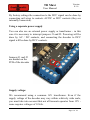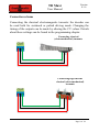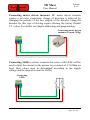
1
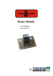
Turnout Decoder TD Maxi User Manual - version 0.1.6 – by TD Maxi User Manual Version 0.1.6 © Copyright 2013 Tehnologistic SRL All rights reserved No part of this publication may be reproduced or transmitted in any form or by any means, electronic or mechanical, including photocopying, without the written permission of SC Tehnologistic SRL Subject to technical modification Please read this manual carefully before carrying out the installation!!! Although our products are very robust, incorrect wiring may destroy the module! During the operation of the device the specified technical parameters shall always be met. At the installation the environment shall be fully taken into consideration. The device must not be exposed to moisture and direct sunshine. A soldering tool may be necessary for the installation and/or mounting of the devices, which requires special care. During the installation it shall be ensured that the bottom of the device should not contact with a conductive (e.g. metal) surface! Page 2 of 24 TD Maxi User Manual Version 0.1.6 Content 1. 2. 3. 4. 5. 6. 7. 8. Features ....................................................................................... 3 Tehnical specification.................................................................. 4 Overview ..................................................................................... 4 Connections and setup ................................................................. 5 Addressing and programming ................................................... 12 Advanced functions ................................................................... 14 Table of decoder CVs ................................................................ 18 Accessory decoder addresses .................................................... 22 1. Features - DCC accessory decoder - usable in any NMRA compatible DCC system - block address in the range 1-512 (or 0-511) - protection against short circuit and overheating - decoder reset by entering any numerical value in CV8 - switching reversal by CV38 - save the last state - duration of output On state programmable in CV3, CV4, CV5, CV6 - programming address mode or continuous programming - DCC command buffer, for sequential switching Page 3 of 24 TD Maxi User Manual Version 0.1.6 2. Technical specification -power supply: DCC signal (from the rails) 9-24Vdc or 17Vac at the AC/DC power connector -total consumption, no activated outputs: <50 mA -maximum output current: 200 mA -maximum pulse current per output: 4000 mA -dimensions: 65 x 85 x 25 mm -weight: 100 g -class of protection: IP00 -operating temperature: 0 to +60 º C -storage temperature: -20 to +60 º C -moisture: max 85% 3. Overview The TD Maxi decoder by tOm is a DCC accessory decoder and can drive 4 turnouts with two electromagnets or with motor drive. It can also be successfully used to drive various accessories: electromagnetic relays, LEDs or incandescent bulbs, etc. The particularity and originality of the decoder is the use of a group of capacitors as an electric charge battery (CDU Capacitor Discharge Unit). With this circuit you can greatly reduce the electrical shock experienced in digital systems when switching a turnout with high power consumption. Capacitors help to create a current pulse for a safer and steady switching. The charging current of the capacitors is constant, without adverse effects for the system (this constant current can be set by CV41). More than that, the start of the charging operation can be delayed randomly after the power up, so in the case of using several TD Maxi decoders on the same layout, the DCC system will be not overloaded at the power on sequence. Page 4 of 24 Version 0.1.6 TD Maxi User Manual 4. Connections and setup Make sure that the turnout or circuit to be connected to the decoder is not powered. Installing under voltage can destroy the decoder. Programing Push-button Power option jumpers Status LEDs AC/DC AC/DC DCC DCC BCA Port1 BCA Port2 BCA Port3 BCA Port4 Connection of the 4 ports (3 terminals each): B C A solenoid terminal corresponding to the branch position (RED wire) (V +) common (positive) terminal of the solenoid solenoid terminal corresponding to direct position (GREEN wire) Page 5 of 24 TD Maxi User Manual Version 0.1.6 By factory settings the connection to the DCC signal can be done by connecting rail wires to contacts AC/DC or DCC contacts (they are internally connected). Using a separate power supply You can also use an external power supply or transformer - in this case it is necessary to interrupt jumpers J1 and J2. Powering will be done by AC / DC contacts, and connecting the decoder to DCC signal will be done by DCC contacts. Jumpers J1 and J2 are market on the PCB of the decoder Supply voltage: We recommend using a common 16V transformer. Even if the supply voltage of the decoder may vary within relatively wide scale, you must take into account that not all turnouts operates from 12V some requires voltages of 16Vdc. Page 6 of 24 Version 0.1.6 TD Maxi User Manual Warning! Output voltage (Vdc) = input voltage (peak) 2V. For AC mains transformer: peak voltage (dc) = output voltage transformer (ac) x 1.42 Meaning of the status LEDs: Status LED color Green (cont) Green (blinking) Red (cont) Decoder in programming mode Red (blinking) Error, short-circuit or other malfunction Normal operation CDU Charging If external power supply is used, the decoder CVs can’t be read out, only programmed. In this case the DCC circuit is optically isolated from the power supply. Page 7 of 24 TD Maxi User Manual Version 0.1.6 Connection scheme Connecting the classical electromagnetic turnouts: the decoder can be used both for sustained or pulsed driving mode. Changing the timing of the outputs can be made by altering the CV values. Details about these settings can be found in the programming chapter. Connecting classical (electomechanical) turnouts Connecting high current classical (electomechanical) turnouts Page 8 of 24 TD Maxi User Manual Version 0.1.6 Connecting motor driven turnouts: DC motor driven turnouts require a two-wire connection; change of direction is achieved by changing the polarity of the two outputs of the decoder. Using the decoder for this type of driving require altering the factory default CV values. For details see chapter addressing and programming. Connecting motor driven turnouts (Conrad, Tillig) Connecting LEDs: resistors connected in series with LEDs will be used to limit the current (in the picture two resistors of 4.7 kOhm are used, their values must be determined according to the supply voltage and the desired current for LEDs) Connecting LEDs Page 9 of 24 TD Maxi User Manual Version 0.1.6 Connecting incandescent bulbs: bulbs can be connected directly to the decoder outputs. Please keep in mind the nominal voltage of the bulbs, which must be rated for a higher voltage than the power supply voltage. Connecting incandescent bulbs Connecting electromagnetic relays: we recommend use of protection diodes connected in parallel with the relay coil. The cathodes of these diodes must be connected to the common wire (positive terminal of the decoder). Connecting electromagnetic relays Page 10 of 24 TD Maxi User Manual Version 0.1.6 Installing the TD Maxi turnout decoders on the layout can be done with the supplied screws and spacers. For positioning and assembly please refer to the figure below: The TD Maxi decoder turnout should be mounted as close as possible to the electromagnetic gear. The electrical connection to them should be made with stranded wire with a suitable section. Cut the wires strictly to the required length. We recommend the use of conductors with minimum cross section of 0.25 -0.5 mm2. Page 11 of 24 TD Maxi User Manual Version 0.1.6 5. Addressing and programming The decoder is programmed to address 1 (T0001) by the factory. This address is for the accessory decoders and is not identical with the locomotive addresses. Between the addressing of the Roco system and other NMRA compliant DCC systems, there is an offset of 4 addresses. Address 0001 of the decoder will be interpreted as address 0005 in a Roco system. To program the decoder, it has to be passed into programming mode by switching the programming push button once. The decoder will acknowledge the entering into programming mode by blinking the green status LED. This cycle takes about 30 seconds, after which the decoder returns to normal operation. If within this time we made the programming of the address, the decoder immediately returns to normal operation. Programming the decoder address with a Roco Multimouse: Switch MultiMouse in the turnout command mode with the Loco/Turnout button Select the desired switch address (Txxxx) using function/numerical keys followed by the OK button. Pass the decoder in programming mode in the way described above. Page 12 of 24 TD Maxi User Manual Version 0.1.6 Perform a straight/branch switch using the direction buttons of the MultiMouse. The decoder will save the address (Txxxx) and will leave the programming mode. Programming the decoder address with a DCC command station: Switch the command in the turnout command mode and select the address you want to program the decoder Pass the decoder in programming mode Perform a straight/branch switch using the direction buttons of the command station The decoder will save the address and will leave programming mode. Page 13 of 24 TD Maxi User Manual Version 0.1.6 6. Advanced functions If you want to customize the decoder by modifying not only the address, but other parameters too, you can do it by changing the values of the CVs specified in the table in Chapter 7. Remove all locomotives or mobile decoders from the rails (decoders in locomotives or carriages) else they will be programmed with the same CV values. CV programming is performed as described in the MultiMouse or command stations manual. To program the decoder, you must switch to programming mode as described in Chapter 5. If you want to program multiple CVs, and you consider the default duration of 30 seconds too short, by writing value “1” in CV40 you can pass decoder in permanent programming mode and you can set all the parameters you want. After programming, write value “0” in CV40, and return to normal programming. If during the permanent programming mode a straight/branch switch operation is executed, the decoder will memorize the transmitted address, and will return to normal operation (will leave the programming mode). You can reload the decoder with the factory default CV values performing a Reset cycle. To do this, program any numerical value in CV8. Page 14 of 24 TD Maxi User Manual Version 0.1.6 The TD Maxi decoder is factory configured for the use of classical electromagnetical (coil type) drives (CV33=0), with ON time for each of the 4 port of 200 miliseconds. The ON time can be configured individually for each of the output ports. The ON time for port1 is stated in CV3 (CV4, CV5, CV6 are used for ports 2,3 and 4). The ON time in miliseconds is given by the coresponding CV value multiplied by 20. For example, a CV value of 10 means 10x20=200 miliseconds. In case of using the decoder with devices which requres continues DC voltage (light bulbs, LEDs, relays), the ON time for the corresponding output has to be settled to continuous ON (CV3 or CV4,5,6 has to be programmed with the value 0). The straight/branch switching direction of each port can be changed in CV38. Bits 0 thru 3 corresponds to the output ports 1 to 4. The 0 value of each bit means normal straight/branch switching, while the 1 value to inversed branch/ straight switching. In CV38 the sum of the values of each bit has to be programmed. The resulting effect is inverted switching for the same sent straight/branch command. The CV39 can change the timeout in the normal address programming mode. Throughout the programming mode the green status LED is blinking. The decoder can save the last state (straight/branch). In this case, even if it was not powered, or its position was changed mechanically, after power-on, the turnout switches in the state saved without receiving a command from the command station. This option is not enabled by default; to enable it you must write the numerical value 1 in CV34. Page 15 of 24 TD Maxi User Manual Version 0.1.6 For using the decoder with motor type drives (Conrad, Tillig), the CV33 has to be programmed with the value of 1. In this case a 2 wire connection is required. The change between straight/branch direction of the turnout is achieved by changing the polarity of the two outputs of the decoder. The ON time in this case is not user programmable, and has a default value of 6 seconds. This timing is sufficient for all motor type turnouts to reach its end position. The motor type drives have internal limit switches, once they reach the end position, the drive motor will be powered OFF, even if the decoder is still in the ON state. The motor type drive mode activation (CV33=1) for the current software version of the TD Maxi decoder (V3 readable in CV7), is valid for all 4 output ports. Once this mode is activated, all the ports will perform in this mode. The TD Maxi deocoder has an internal overcurrent and over temperature protection which is active by default (CV35 = 1). This can be turned OFF programming CV35 with the value 0. Using the motor type drive mode (CV33=1) for the current software version of the TD Maxi decoder (V3 readable in CV7), the current protection has to be turned OFF. Once an error condition is encountered on any of the outputs of the decoder (overcurrent, overtemperature), the corresponding output will be switched OFF, and its status is recorded in the error CV30, which can be read out. The error condition is displayed with the red status LED which will be continuously ON. Bits 0 thru 7 of the CV30 are assignated to the 8 outputs of the decoder ( 4 ports with 2 outputs each). Bit0 coresponds to port 1, output 1, bit1 to port1 ouput 2, and so on. The 0 value for each bit means no error on the Page 16 of 24 TD Maxi User Manual Version 0.1.6 corresponding output, while the 1 value means error encountered since the last clearing operation. The readout value is the sum of bits 0-7. The error status can be cleared, by programming CV30 with the value 0. Between succesive switching of its outputs, the DCU is charged and no command will be executed. To avoid loosing of turnout switching commands transmitted by the command station during the charge period, the TD Maxi decoder has implemented a 16 command waiting list which will be executed in sequence. The constant charging current is selectable between 300 mA (factory default value, CV4 =1), and 150 mA (CV41 = 0). Lower charging current will result in a longer charging time. The activations of the outputs will be performed once the CDU has completelly charged. At the time when the decoder is powered from the DCC system or from an external power source, the CDU is charged. If several units are present on the same layout this can result in a high load of the system, and the command station or boosters could go into over current protection. TD Maxi has implemented a mechanisn to avoid these kind of situations, using an ofsetted waiting state at power up. The power up of the decoders will be made sequentially, one by one in the order of their block address. The offset time between the power on of two decoders can be settled in CV42. Using this algorith, the current load of the system will be kept low at the power ups. For direct address programming of the decoders thry CV1 and CV9, please take a look to chapter 8. Page 17 of 24 Version 0.1.6 TD Maxi User Manual 7. Table of decoder CVs 1 3 1 10 Value Range 0-63 0-255 4 10 0-255 5 10 0-255 CV Default Value Description Base (block) address of the decoder (6 bits) The duration of ON state of the decoder’s port1 outputs. Activation time = value CV3 x 20 msec. Example: CV3 = 10, pulse duration = 10 x 20 msec = 200 msec (milliseconds). In case of CV3=0, the output of the port will be permanently ON, while the decoder will receive an activation command to the complementary output of the port The duration of ON state of the decoder’s port2 outputs. Activation time = value CV4 x 20 msec. Example: CV4 = 10, pulse duration = 10 x 20 msec = 200 msec (milliseconds). In case of CV4=0, the output of the port will be permanently ON, while the decoder will receive an activation command to the complementary output of the port The duration of ON state of the decoder’s port3 outputs. Activation time = value CV5 x 20 msec. Example: CV5 = 10, pulse duration = 10 x 20 msec = 200 msec (milliseconds). In case of CV5=0, the output of the port will be permanently ON, while the decoder will receive an activation command to the complementary output of the port Page 18 of 24 TD Maxi User Manual 6 10 0-255 7 8 3 78 - 9 30 0 0 0-7 0-255 Version 0.1.6 The duration of ON state of the decoder’s port4 outputs. Activation time = value CV6 x 20 msec. Example: CV6 = 10, pulse duration = 10 x 20 msec = 200 msec (milliseconds). In case of CV6=0, the output of the port will be permanently ON, while the decoder will receive an activation command to the complementary output of the port Firmware version (only readable) Manufacturer ID (train-O-matic, only readable). Any numerical value written in the CV will reset the decoder to factory defaults (see “Default Value” column) Extended block address of the decoder , value between 0 and 7 (3 bits) Error, Short at output (the read out value is the sum of the errors): 1 = short on port 1 output1 2 = short on port 1 output2 4 = short on port 2 output1 8 = short on port 2 output2 … 64 = short on port 4 output1 128 = short on port 4 output2 Page 19 of 24 TD Maxi User Manual 33 0 0/1 34 0 0/1 35 1 0/1 38 0 0-15 Version 0.1.6 Coil Type mode/ Motor Type mode) 0=coil type mode 1=motor type mode (outputs active with complementary polarity with 6 second ON time) 0 -No save / do not remember the last state 1 - Save / remember last state 0-current protection OFF 1-current protection ON Switching direction configuration (straight/branch) for each port of the decoder. CV38 has to be programmed with the sum of the options (values in brackets) Bit 0 = 0(0): Normal switching direction (straight/branch) port 1 = 1(1): Inverted switching direction (branch/straight) port 1 Bit 1 = 0(0): Normal switching direction (straight/branch) port 2 = 1(2): Inverted switching direction (branch/straight) port2 Bit 2 = 0(0): Normal switching direction (straight/branch) port 3 = 1(4): Inverted switching direction (branch/straight) port 3 Bit 3 = 0(0): Normal switching direction (straight/branch) port 4 = 1(8): Inverted switching direction (branch/straight) port 4 Page 20 of 24 TD Maxi User Manual 39 30 1-255 40 0 0/1 41 0 0/1 42 0 0-15 Version 0.1.6 Duration while the decoder remains in programming mode. Factory value is 30 seconds; after that the decoder exits programming mode 0 - Exiting programming mode 1 - Entering continuous programming mode 0-charge current of the CDU of 300 mA 1- charge current of the CDU of 150 mA Charge Delay of the CDU after power up of the decoder Charge Delay: 0=200ms, Delay=(value of CV42 + 1)*200ms Page 21 of 24 TD Maxi User Manual Version 0.1.6 8. Accessory decoder addresses According to NMRA standards, accessory decoder addresses are organized into groups of four addresses, called block addresses (often called “decoder address”). There are a total of 512 block / decoder addresses so we can drive a maximum of 2048 (512 x 4 = 2048) turnouts. Although most digital command stations (including the Roco), displays the individual address of the decoder, for correct address should keep in mind the relationship between the block / decoder address and individual turnout address. The block addresses of the accessory decoders are determined using CV1 and CV9 (in binary CV1 uses 6-bit, resulting decimal values in the range 0-63 and CV9 uses 3 bits, resulting decimal values in the range 0-7). The formula for block/decoder address is: block address = CV1 + 64*CV9 Most decoders contain control circuits for 4-8 turnouts, and the block/decoder address implicitly assign addresses for the 4-8 outputs in consecutive order. The Roco system allows the use of block address “0” and for this reason there is an offset of 4 individual addresses. On the next page we have presented a partial table with individual addresses by CV1and CV9. The full table can be found on our website. Page 22 of 24 Version 0.1.6 TD Maxi User Manual Block/ Decoder Address Individual turnout addresses of the TD Maxi ports CV9 Value CV1 Value Port 1 Port 2 Port 3 Port 4 individual addresses 1 2 3 4 5 6 ………. 60 61 62 63 64 65 66 67 68 69 70 ………. 125 126 127 128 0 0 0 0 0 0 ………. 0 0 0 0 0 1 1 1 1 1 1 ………. 1 1 1 1 1 2 3 4 5 6 ………. 60 61 62 63 64 1 2 3 4 5 6 ………. 61 62 63 64 1 5 9 13 17 21 ………. 237 241 245 249 253 257 261 265 269 273 277 ………. 497 501 505 509 2 6 10 14 18 22 ………. 238 242 246 250 254 258 262 266 270 274 278 ………. 498 502 506 510 3 7 11 15 19 23 ………. 239 243 247 251 255 259 263 267 271 275 279 ………. 499 503 507 511 4 8 12 16 20 24 ………. 240 244 248 252 256 260 264 268 272 276 280 ………. 500 504 508 512 Page 23 of 24 TD Maxi User Manual Version 0.1.6 Copyright © 2013 Tehnologistic SRL All rights reserved The information in this document is subject to change without notice “train-o-matic” and the logo are registered trademarks of SC Tehnologistic SRL www.train-o-matic.com www.tehnologistic.ro Tehnologistic SRL Str. Libertatii Nr. 35A 407035 Apahida, Cluj Romania Tel +40-264-556454 Fax +40-264-441275 Page 24 of 24