1
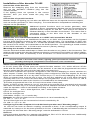
Multi-Protocol decoder with Load Regulation with RailCom®
for DC and Faulhaber motors
Features
•
•
•
•
•
•
•
•
•
•
•
•
•
•
•
•
•
•
•
•
Multi-protocol Load regulated decoder for DCC and Motorola
Suitable for DC and bell armature motors to 1 A
Quiet motor running by using 18.75 kHz control frequency
14, 27, 28, 128 speed steps, depending on data format
Short addresses (1-127) and long addresses (for 128-9999)
NMRA compliant
RailCom
Adjustable minimum, maximum and medium speeds
Speed step tables for 14 and 28 speed step mode
Main track programming (DCC)
Shunting mode (half speed) toggled using F3
Starting/brake inertia switched using F4
Headlights switched using F0, dimmable
2 special function outputs switched using F1 and F2, dimmable or time restricted
With SUSI sound interface (4 pole mini socket) for the connection of sound modules or
other modules, controllable using auxiliary functions (f1 to f12)
Produces the address identification for the control of the LISSY of mini transmitter 68 400
Reacts to DCC conforming brake signal or brake sections with DC voltage
Overheating protection, all output are short circuit protected
Conventional DC or AC operation with automatic change
All CV's are programmable with digital devices using DCC and/or Motorola formats
Description
The locomotive decoder 76 425 is a small, efficient multi-protocol decoder. It can be used in
DCC and Motorola systems and operates equally well in analog mode with DC or AC power
and direction of travel change-over using high voltage pulse (Märklin system).
The decoder works with a frequency of 18.75 kHz and is not only suitable for DC motors, but
also for bell armature motors (e.g. Faulhaber, Maxon, Escap) up to a continuous power of 1 A.
Short term higher switching on current are tolerated well.
The motor characteristics are setup either by means of the minimum, middle and maximum
speeds or by different CV's for the individual speeds. The load control can be individually
adapted to different locomotive motors by setting these control parameters.
The decoder has two travel direction dependent lighting outputs, as well as two additional
special function outputs, which are switched using function keys f1 and f2. Function keys f3
and f4 can be used to switch a shunting mode with extended low-speed operating range and
the starting/brake inertia. The allocation of the switching tasks such as lighting, special
function outputs, shunting mode and adjustable starting/brake inertia can be freely assigned to
the function keys of the digital center (Function Mapping). For operating e.g. electric couplers,
the special function outputs can be time limited and if desired the motor can be activated for a
short time (shunting tango).
Head and tail lighting can be switched off, depending on the direction, via the special function
outputs (Train switchable lighting).
The decoder is programmable with the Intellibox, DCC and Märklin controllers. All CV's are
programmable with these devices.
Ex-Factory Setting
Ex-factory the decoder is configured in DCC/Motorola operating mode. It switches between
the two formats automatically. Additionally the decoder can be controlled with a DC device or
AC transformer (Märklin System) in analogue 2-rail or 3-rail installations.
Installation of the decoder 76 425
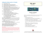
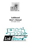
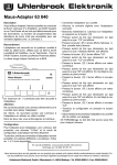
Connection of the decoder
Remove the strapping plug from the locomotive
and put the decoder’s interface plug into the
vacated socket.
If the lighting does not operate in the correct
direction, then you must rotate the plug 180
degrees.
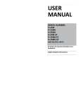
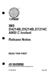
Connection of special functions
Besides lamps for lighting you can also use different items on the special functions outputs,
such as smoke generator or Telex-coupling. For travel direction independent switching the
outputs can be paralleled.
Additional special functions such as smoke generator, telex
coupling or driver compartment lighting can be connected to the
special function outputs A1 and A2. The feed to the device is
soldered directly to the decoder circuit board. The return line is
connected either to the blue wire of the decoder or the
locomotive chassis.
Connection of an IntelliSound module or a LISSY mini transmitter 68 400
Alternatively a plug from an IntelliSound module or a LISSY mini transmitter can be inserted
into the SUSI interface socket on the under side of the decoder. For controlling a LISST mini
transmitter program Bit 1 in CV49 to 1 so that the decoder sends the identification address for
the control of the LISSY mini transmitter to the SUSI interface. For operating a sound module
on the SUSI-interface, Bit 1 in CV49 must be set to 0 (Factory setting).
Mounting the decoder in the locomotive
Use the enclosed double-sided tape to fasten the decoder to any place in the locomotive. The
sticking pad protects the decoder against conductive connections and holds it in place reliably.
Ensure that even after re-assembly of the locomotive no short-circuits occur from jammed
wires.
A short-circuit in the area of the motor, lighting, pick-up and wheel contacts can
possibly destroy the component and electronics of the locomotive!
Switch off train lighting front and rear
In CV107 (front) and CV108 (rear) the special function number 1-12, which will turn off the
white and the red light front and rear, can be entered. It can also be programmed here which
function output has the red end of the train light connected to it.
The function entered here must be configured in the Function-Mapping so that it switches no
other outputs. Further, the Function-Mapping must configured so that the outputs for the red
lights are not switched off or on by other function keys, i.e. the Function-Mapping CV for f-key
which is entered here must be set to zero. So that the switching off of the lights functions
correctly both CV's 107 and 108 must always be programmed. If one of CV's 107 or 108 is
programmed with the value 0 the function is considered to be deactivated.
The value programmed into CVs 107 and 108 consists of two parts.
Firstly, to which of the outputs A1 to A7, the light to be turned off is connected and secondly
with which function key f1 to f12 the lighting is to be switched. Because a CV can only contain
value the operation value is calculated according to the follow schema:
Light allocation:
A0v = white light front, A0h = white light rear
CV107 for red light front
CV108 for red light rear
Calculation: Output * 16 + function key
Example: the red front light is to be connected to A1 and controlled by f5.
CV 107 = 1 * 16 + 5 = 21
The red front light is to be connected to A2 and controlled by f6.
CV 108 = 2 * 16 + 6 = 38
Configuring Function Outputs A1 and A2 timed operation and "Shunting tango"
A1 and A2 can have an electric coupling connected to them. If the corresponding output is
switched on it stays on for the time specified in CV 99. If additionally the locomotive’s motor is
to operate for this time then “Shunting tango” must be activated in CV100.
RailCom
If the locomotive decoder is to operate with RailCom, Bit 3 of CV 29 must be set. Additionally
the Motorola Format in CV 12 must be switched off.
Märklin braking section
The decoder reacts to a Märklin brake section (brakes with analog power on the track), if CV29 bit 2
and CV49 bit 7 are set to 1 (factory setting 1 and 0).
Programming
The Configuration variables (CV's) form the basis of all possible operations of the decoder in
accordance with the DCC standard. The decoder can be programmed with the Intellibox, DCC
controllers and Motorola controllers.
Programming with the Intellibox
We recommend that, irrespective of the data format that will eventually be used, the decoder
be programmed using the menu for DCC decoders.
The Intellibox supports DCC programming with a user friendly input menu. Long addresses
do not have to be calculated laboriously, as they can be entered directly. The Intellibox
calculates the values for CV 17 and CV 18 automatically.
Besides this the Intellibox sets Bit 5 of CV29 to 1 so the decoder uses the long address.
Special case locomotive addresses 80 to 255 in Motorola format
In Motorola format the Intellibox supports an address range to 255. Addresses 1 to 80 can
also be programmed freely using DCC programming. However if locomotive addresses higher
than 80 are to be used, the locomotive address must be programmed according to the chapter
"Programming with a Märklin controller".
After programming is complete CV 1 has a value of 0 and the decoder uses the Motorola
address larger than 80.
Programming with DCC devices
Use the programming menu of its DCC controller to select and program the decoder’s CV's by
register, CV directly or page mode programming. With a DCC controller it is also possible to
program the decoder using main line programming. For the exact procedure refer to the
controller user manual.
Programming of long addresses without programming menu
If programming is to be done with controllers that do not support programming with an input
menu, the values for CV 17 and CV 18 must be calculated. Here is a guide for programming of
address 2000.
•
Divide the address by 256 (2000/256 = 7 remainder of 208).
Take the integer result (7) and add 192
• Program the result (199) into CV 17
• Program the remainder (208) into CV 18
Important: Set bit 5 of CV 29 to 1, so that the decoder uses the long address.
•
Values for calculating the CV value
CV's 29 and 49 can be used to set the decoder into different modes. The value to be
programmed is calculated by using the CV and adding the values of the desired functions.
Example
Normal driving direction
Value = 0
28 speed steps
Value = 2
Auto Analog/digital change over Value = 4
RailCom switched off
Value = 0
Speed steps using CV 2, 5, 6
Value = 0
Short address
Value = 0
The sum of all values is 6.
CV 29 preset to this value ex factory.
Bit
0
1
2
3
4
5
CV 29 function
Normal driving direction
Reverse driving direction
14/27 speed steps
28/128 speed steps
Only digital operation
Automatic analog/digital change over
RailCom switched off
RailCom switched on
Speed steps using CV2, CV5 and CV6
Characteristics using CV67-CV94
Short address (CV1, register 1)
Long address (CV17 and CV18)
Programming with a Märklin Center (not CS2, MS2 see DCC)
With a Märklin center all CV's can be programmed, but not read.
1. Switch Center off and on.
2. Select the address of the decoder and switch the light on.
3. Operate the direction change-over 5 times in quick succession with the stationary
locomotive (speed step 0), until the light turns off.
4. Enter the number of the CV that is to be programmed.
5. Enter the locomotive address on the center that is program the CVs.
6. Briefly operate the direction change-over. The rear light flashes fast 4 times.
Value
0
1
0
2
0
4
0
8
0
16
0
32
7. Enter the desired value for CV e.g. a locomotive address.
8. Briefly operate the direction change-over. The rear light flashes slowly 4 times.
If further CVs are to be programmed, repeat points 5-8.
If programming is to be terminated switch the center to “STOP” or set the address to 80 and
briefly operate the direction change-over.
Note: Since programming with a Märklin Motorola digital center accepts only inputs of 01 to 80,
the value “0” must be entered by entering the address as “80”.
Page-Register for inputting CV-Numbers greater than 79
CV addresses larger than 79 can only be programmed with the help of the page register,
CV66. If CV66 has a value higher than 0, then the contents of CV66 times 64 will be added to
every address entered. The entered value must lie in the range 1 to 64. When leaving
Motorola programming mode the page register (CV66) is automatically reset to zero.
Offset-Register for entering CV values greater than 79
CV values larger 79 can be programmed only with the help of the offset register. The offset register
is CV65. If CV65 contains a value > 0, then all following programmed values are calculated by
multiplying the contents of CV65 by 4 and adding the result to the entered value. When leaving
Motorola programming mode the offset register (CV65) is automatically reset to zero.
Note: When programming CV65 and CV66 the contents of the offset and page registers have no
effect.
Programming with a Mobile Station 1
The Programming Menu is available in the Mobile Station‘s Loco Menu, only for certain
locomotives. A locomotive which is equipped with a programmable decoder must be selected
from the Database. Proceed as follows:
1. Add a new locomotive and select Part No. 36330. The Display then shows locomotive Ee
3/3.
2. Press the "MENU/ESC" button and select the “LOK Change” ("LOK ÄNDERN") column.
Here you will find the last function of Register Programming indicated by "REG". Use this
function to change the decoder’s CV's. You can only write to the CV's with this function.
3. Enter the number of the CV and confirm this with the reversing knob.
4. Enter the value for the CV and confirm this with the reversing knob. The Mobile Station
then programs the CV with the desired value.
Attention: Before programming, remove all locomotives that are not to be programmed from
the track!
Motor Regulation
The motor’s load regulation can be adapted to suit the locomotive with CVs 53 to 58.
Guide for changing the controller parameters P,I,D:
1.) Set CV54, 55 and 57 with factory setting of the decoders CV2, 5 und 6 (min., max. and
middle Speed).
2.) Set CV55 and 57 to zero
3.) Set CV54 so that the locomotive just moves on speed step 2.
4.) Increase CV55 so that the locomotive moves off quickly, as desired, when changing the
speed step from 0 to 1. (The step size should be 1.)
5.) Jerky behaviour with the change of speed step can be compensated for in CV57. (The
step size should be 1.)
6.) If necessary adapt CV2, 5, 6 from step 2.) and start over with the adjustments.
If no satisfactory result can be obtained then you must
a) change the regulation repetition rate in CV53.
b) Increase the measuring time for the back EMF voltage in CV58. (With some motors
smooth running can only be achieved at low speed in this way.)
c) reduce the regulation frequency in CV56. (this is valid when the locomotive already runs at
top speed at a speed step lower than the maximum and after no further change in speed
occurs)
Make the respective changes to CV53, 56, 58 in small increments and if necessary repeat the
PID regulation in points 1.) to 6.).
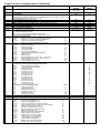
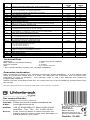
Table of CVs (Configuration Variables)
CV
Description
1
Locomotive address
2
3
Minimum Speed
Acceleration
1 means that every 5 ms the actual speed is increased by 1
If the internal maximum speed is set to 200 (CV5=50 or CV94 = 200), then
acceleration time from 0 to Fmax is 1sec.
Braking inertia (time factor CV3)
Maximum speed (must be greater than CV2)
Middle speed (must be greater than CV2 and less than CV5)
Software version (The processor can be updated)
Manufacturer ID
Long locomotive address
17 = high byte / 18 = low byte
Consist address (double traction)
0 = Consist address inactive
When bit 7=1 the driving direction is reversed
The desired speed CADR + 128 = reverse direction
RailCom Configuration
0*
Bit 0=0
Channel 1 not free for address broadcast
1
Bit 0=1
Channel 1 free for address broadcast
0
Bit 1=0
Channel 2 no data transmission
2
*
Bit 1=1
Channel 2 data transmission allowed
Configuration for DCC
Value
0*
Bit 0=0
Normal direction
1
Bit 0=1
reversed travel
0
Bit 1=0
14 speed steps
2
*
Bit 1=1
28 speed steps
0
Bit 2=0
Only digital operation
4*
Bit 2=1
automatic analog/digital switching
0*
Bit 3=0
RailCom Off
8
Bit 3=1
RailCom On
0*
Bit 4=0
Speed steps using CV 2, CV 5, and CV 6
16
Bit 4=1
Characteristics using CV 67 to CV 94
0*
Bit 5=0
Short address (CV 1)
32
Bit 5=1
Long address (CV 17/18)
Allocation of the function outputs, which are to be activated with
function keys like light and special functions
CV33
Light operation forwards
CV34
Light operation backwards
CV35
Function key f1
CV36
Function key f2
CV37
Function key f3
CV38
Function key f4
CV39
Function key f5
CV40
Function key f6
CV41
Function key f7
CV42
Function key f8
CV43
Function key f9
CV44
Function key f10
CV45
Function key f11
CV46
Function key f12
Assignment of the individual Bits
Value
1
Light output front
Bit 0
2
Bit 1
Light output back
4
Bit 2
Special function A1
8
Special function A2
Bit 3
Shunting mode
16
Bit 4
Start/brake inertia
32
Bit 5
Speed correction forwards
Speed correction reverse
Locomotive decoder configuration
Value
Bit 0=0
Motor load regulation On
0*
Bit 0=1
Motor load regulation Off
1
Bit 1=0
SUSI configured for Sound module
0*
Bit 1=1
SUSI configured for LISSY Mini transmitter
2
Bit 2=0
brakes to 0 in brake section
0*
Bit 2=1
brakes to speed step in CV52
4
Bit 3=0
Data format DCC and Motorola
0*
Bit 3=1
Data format only DCC
8
Bit 4=0
Data format DCC and Motorola
0*
Bit 4=1
Data format only Motorola
16
Bit 5=0
Dimming for A1 and A2 Off
0*
Bit 5=1
Dimming for A1 and A2 On
32
Bit 6=0
Light outputs not swapped
0*
Bit 6=1
Light outputs swapped
64
Bit 7=0
Brake only with brake signal
0*
Bit 7=1
Brake with analog potential
128
4
5
6
7
8
17
18
19
28
29
33-46
47
48
49
Value
range
Default
value
DCC 1-127
Mot 1-80
1-63
1-63
1
2
1-63
1-63
1-63
1-9999
199-231/0-255
1-127
2
48
24
varies
85
2000
199/208
0
3
3
0-255
6
0-63
1
2
4
8
16
32
0
0
0
0
0
0
0
0
0-63
0-63
0-255
32
32
32
CV
Description
Value
range
Default
value
50
Dimming of Function outputs A1, A2 and Light outputs
0-63
32
51
Final speed in a braking section
1 = only AC operation, 2 = only DC operation
3 = AC and DC operation with automatic recognition
Motor regulation repetition rate
Motor regulation P Constant
Motor regulation I Constant
Regulation Frequency
Motor regulation D Constant
Time slot for AD transducer measurement
Reset to factory defaults
If this CV is set to 1, the decoder will be returned to factory setting.
Monitoring of Outputs switching off
0=All on, 1=Motor off, 2 Light, A1, A2 off, 4=Temperature
Shutdown temperature in °C
0 = Temperature monitoring off (do not change)
Error Buffer for Short Circuit reporting, temperature monitoring
0 = no reporting, 1 = Motor, 2 = Light, A1, A2, 4 = Temperature
Speed at the end of the Braking section
Applies if CV49 Bit 2=1 and Bit 7=1
Offset-Register
For CV Programming with a Motorola center
Page Register
For CV Programming with a Motorola center
Characteristic curve for speed steps 1-28
Timed switching of Outputs A1 and A2
0 = A1 and A2 have timed restriction
1 = A1 has timed switching
2 = A2 has timed switching
3 = A1 and A2 have timed switching
Length of the time switching
In 100ms: A value of 10 represents 1 second
Coupling repeats for electric couplings on A1 and A2
Switch front light off
Switch rear light on
LISSY Train catagory
1-3
3
0-63
0-63
0-63
0-63
0-63
0-63
0, 1
35
20
10
32
12
2
0
0, 7
0
0-2
2
53
54
56
56
57
58
59
60
61
62
64
65
66
67-94
98
99
100
107
108
115
0-7
0
0-255
30
0-255
0
0-255
0
0-255
0-3
varies
0
0-255
0
0-255
0-44
0-44
1-4
0
0
0
1
Technical Data
Addresses:
Max. current consumption/loading:
Function outputs:
Size:
1-9999 (long DCC address)
1.4 A*
1 A each
22 x 12.5 x 5.5 mm
* The constant loading capacity may vary after installation.
Guarantee declaration
Each component is tested for its complete functionality before distribution. If a fault should arise
within the guarantee period area of 2 years, we will repair the component free of charge upon
production of proof of purchase. The warranty claim is void if the damage was caused by
inappropriate treatment.
Please note that, according to EMV law, the component may only be installed in vehicles which carry
the CE logo.
The trade names mentioned are registered trade marks of the respective companies.
Our contact Details:
We are available if you have any questions!
Internet: FAQs are found at www.uhlenbrock.de
E-Mail:
[email protected]
Hotline: +49 (0) 2045 8583-27, Wed 16:00~18:00
and Mon - Tue - Thu – Fri, 14:00~16:00
Uhlenbrock Elektronik GmbH
Mercatorstr. 6
D-46244 Bottrop
Service:
Made in Germany
In the event of a defect or failure send the unit
together with the invoice and a short description of
the fault back to us for repair.
Electronic devices do not
belong in household rubbish
Part No. 76 425