1
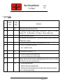
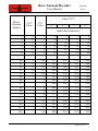
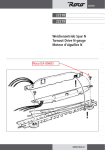
Roco Turnout Decoder User Manual - version 0.0.6 – by Roco Turnout Decoder User Manual Version 0.0.6 © Copyright 2012 Tehnologistic SRL All rights reserved No part of this publication may be reproduced or transmitted in any form or by any means, electronic or mechanical, including photocopying, without the written permission of SC Tehnologistic SRL Subject to technical modification Please read this manual carefully before carrying out the installation!!! Although our products are very robust, incorrect wiring may destroy the module! During the operation of the device the specified technical parameters shall always be met. At the installation the environment shall be fully taken into consideration. The device must not be exposed to moisture and direct sunshine. A soldering tool may be necessary for the installation and/or mounting of the devices, which requires special care. During the installation it shall be ensured that the bottom of the device should not contact with a conductive (e.g. metal) surface! Content 1. 2. 3. 4. 5. 6. 7. 8. Features ....................................................................................... 3 Tehnical parameters .................................................................... 3 General description ..................................................................... 4 Wiring and mounting .................................................................. 4 Addressing and programming..................................................... 6 Special functions ......................................................................... 8 CV Table ................................................................................... 10 Accessory decoder addresses .................................................... 11 Page 2 of 13 Roco Turnout Decoder User Manual Version 0.0.6 1. Features - DCC accessory decoder, compatible with Roco Geoline © - Usable in any NMRA compatible DCC system - Individual addresses in the range of 1-2048 - Powered from the polarity switch of the heart of the turnout - Protection against short circuit and overheating - Decoder reset by entering a numerical value in CV8 - Inverted switching programmable from CV38 - Possibility of saving the last state - Duration of switching programmable from CV3 - Address programming mode or continuous programming mode 2. Tehnical parameters - Power supply voltage: 4-24 V rail voltage (DCC) - Power consumption without activated outputs: <10 mA - Maximum output current: 200 mA - Maximum current / decoder: 400 mA - Dimensions: 35x20x4 mm - Weight: 4 g - Class of protection: IP00 - Operating temperature: 0 to +60 º C - Storage temperature: -20 to +60 º C - Moisture: max 85% Page 3 of 13 Roco Turnout Decoder User Manual Version 0.0.6 3. General description The tom Roco TD (turnout decoder) has been developed specially for driving Roco Geoline © turnouts and it is functionally equivalent to the standard Roco 61196 decoder. The decoder works with Roco 61195 turnout drivers. The decoder is compatible with right / left turnouts (61141/61140), curved right/left turnouts (61155/61154), DKW type crossings (61164) and three-way turnouts type DWW (61160). In the same system can be used both original decoders 61196, and tom Roco TDs too, being 100% compatible. 4. Wiring and mounting Make sure the turnout in which you want to install the decoder is not powered. Installing under voltage can destroy the decoder. The decoder connects directly to 61195 turnout driver through a subminiature connector. For driving an electromagnetic turnout, see its documentation. Connect the power cable and polarization of the heart (three wires: blue / yellow / orange) to the electromagnetic actuator as shown. Pay attention to color correspondence between the connector and the label on the actuator. Page 4 of 13 Roco Turnout Decoder User Manual Version 0.0.6 Insert the decoder in the electromagnetic actuator fitting the 5-pin connector in the drive’s connector. Depending on the type of switch, the decoder can be installed either behind or facing outwards. Between the 3-pin power connector of the decoder and the 5-pin one must remain one free pin at the actuator’s connector. Pay special attention to proper introduction of the decoder pins in the electromagnetic actuator, without bending them. Wrong connection may cause malfunction or damage the decoder! Page 5 of 13 Roco Turnout Decoder User Manual Version 0.0.6 Mount the decoder to turnout carefully with the supplied screw in the decoders package. Do not force the tightening to avoid damaging the plastic threads of the turnout body. 5. Addressing and programming The decoder is programmed to address 1 (T0001) by the factory. This address is for the accessory decoders and is not identical with the locomotive addresses. Between the addressing of the Roco system and other NMRA compliant DCC systems, there is an offset of 4 addresses. Address 0001 of the decoder will be interpreted as address 0005 in a Roco system. To program the decoder, it has to be passed into programming mode by manual switching the turnout five times between straight and branch position. Page 6 of 13 Roco Turnout Decoder User Manual Version 0.0.6 The decoder will acknowledge the entering into programming mode by consecutive switchings of the turnout between straight and branch positions in a cycle that takes about 30 seconds, after which the decoder returns to normal operation. If at this time we made the programming of the address, the decoder immediately returns to normal operation. Programming the decoder address with a Roco Multimouse: Switch MultiMouse in the turnout command mode with the Loco/Turnout button Select the desired switch address (Txxxx) using function/numerical keys followed by the OK button. Pass decoder in programming mode in the way described above. Perform a straight/branch switch using the direction buttons of the MultiMouse. The decoder will save the address (Txxxx) and will leave the programming mode Programming the decoder address with a DCC command station: Switch the command in the turnout command mode and select the address you want to program the decoder Pass decoder in programming mode Perform a straight/branch switch using the direction buttons of the command station The decoder will save the address and will leave programming mode Page 7 of 13 Roco Turnout Decoder User Manual Version 0.0.6 The values of the decoder CVs can not be read, only written in regular programming mode. To allow the reading of the CV values during the programming, please write value 2 to CV40. The decoder is supplied with optimally set parameters. To change other CVs then the decoder address, please refer to the next chapter. 6. Special functions If you want to customize the decoder by modifying not only the address, but other parameters too, you can do by changing CVs specified in the table in Chapter 7 - CV Table. Remove all locomotives from the rail, or mobile decoders on rail (decoders in locomotives) will be programmed with the programmed CV values. CV programming is performed as described in the MultiMouse or command stations manual. To program the decoder, you must switch to programming mode as described in Chapter 5 - Addressing and programming. If you want to program multiple CVs, and the default duration of 30 seconds you consider too short, by writing value “1” in CV40 you can pass decoder in permanent programming mode and you can set all the parameters you want. After programming, write value “0” in CV40, and return to normal programming. During permanent programming the decoder executes all switching commands, but to return to normal, it is required to re-register value “0” in CV40. Otherwise, all CV changing commands submitted to any other decoders will be interpreted by the decoder in permanent programming mode. Page 8 of 13 Roco Turnout Decoder User Manual Version 0.0.6 If you wish to read the CV vakues during the programming, please write the numerical value 2 instead of 1 in CV40. The decoder will acknowledge the CV values to the command station during the readout, actuating the electromagnets of the turnout drive. Please write the numerical valu 1 to CV40 after you have finished the programming. To reset the decoder to factory defaults (“Default Value” column in the CVs table) enter any numeric value in CV8. The pulse output duration of the electromagnetic actuator can be changed from CV3. Duration value in milliseconds is given by the numerical value recorded in CV3 multiplied by 20. For example, the value 10 recorded in CV3 means 10 x 20 = 200 milliseconds. Normal switching direction of the turnout can be inverted by entering the value “1” in CV38. The resulting effect is inverted switching for the same sent straight/branch command. The CV39 can change the timeout in the normal address programming mode. Throughout the normal programming mode, the decoder swithes between straight and branch positions. The decoder can save the last state (straight/branch). In this case, even if it was not powered, or its position was changed mechanically, after power-on the turnout switches in the state saved without receiving a command from the command station. This option is not enabled by default, to enable it you must write the numerical value 1 in CV34. Direct programming of the decoder’s address with CVs is described in Chapter 8 – Accesory decoder adresses. Page 9 of 13 Roco Turnout Decoder Version 0.0.6 User Manual 7. CV Table Default Value CV Value Range 1 3 1 10 0-63 - 7 8 1 78 - 9 34 0 0 0-7 0/1 37 38 1 0 1-4 0/1 39 30 0-255 40 0 0/1/2 Description Base (block) adress of the decoder (6 bits) The duration of driving the decoder output. Activation time = value CV3 x 20 msec. Example: CV3 = 10, pulse duration = 10 x 20 msec = 200 msec (milliseconds) Firmware version (only readable) Any numerical value written in the CV will reset the decoder to factory defaults (see “Default Value” column) Extended block address of the decoder , value between 0 and 7 (3 bits) 0 - No save / not remember the last state 1 - Save / remember last state Position address of the decoder ( 1..4) 0 - Normal switching direction (straight/branch) 1 – Inverted switching direction (branch/straight) Duration when the decoder remains in programming mode. Factory value is 30 seconds; after that the decoder exits programming mode 0 - Exiting programming mode 1 - Entering continuous programming mode 2 - Entering continuous programming mode with acknowledge (allowing the readout of the CV-s during the programming) Page 10 of 13 Roco Turnout Decoder Version 0.0.6 User Manual 8. Accessory decoder addresses According to NMRA standards address decoders and accessories are organized into groups of four addresses, called block addresses (often called “decoder address”). There are a total of 512 block / decoder addresses so we can drive a maximum of 2048 (512 x 4 = 2048) turnouts. Although most digital command stations (including the Roco), displays the individual address of the decoder, for correct address should keep in mind the relationship between the block / decoder address and individual turnout address. Block address of the accessory decoders is determined using CV1 and CV9 (in binary CV1 uses 6-bit resulting decimal values in the range 0-63 and CV9 uses 3 bits, resulting decimal values in the range 0-7). The formula for block/decoder address is: block address = CV1 + 64*CV9 Most decoders contain control circuits for 4-8 turnouts, and the block/decoder address implicitly assign addresses for the 4-8 outputs in consecutive order. If decoders are addressed individually (as in tom Roco TD) you must specify the individual address in the group. Thus we specify the number of the turnout inside the group in CV37 (1-4). The individual address is calculated as follows: individual address = (block address - 1)*4 + CV37 Roco system allows the use of block address “0” and because of this there is an offset of 4 individual addresses. On the next page we have presented a partial table with individual addresses by CV1and CV9. The full table can be found on our website. Page 11 of 13 Roco Turnout Decoder Version 0.0.6 User Manual Value CV37 Block/ Decoder Address CV9 Value CV1 Value 1 2 3 4 individual addresses 1 2 3 4 5 6 ………. 60 61 62 63 64 65 66 67 68 69 70 ………. 125 126 127 128 0 0 0 0 0 0 ………. 0 0 0 0 0 1 1 1 1 1 1 ………. 1 1 1 1 1 2 3 4 5 6 ………. 60 61 62 63 64 1 2 3 4 5 6 ………. 61 62 63 64 1 5 9 13 17 21 ………. 237 241 245 249 253 257 261 265 269 273 277 ………. 497 501 505 509 2 6 10 14 18 22 ………. 238 242 246 250 254 258 262 266 270 274 278 ………. 498 502 506 510 3 7 11 15 19 23 ………. 239 243 247 251 255 259 263 267 271 275 279 ………. 499 503 507 511 4 8 12 16 20 24 ………. 240 244 248 252 256 260 264 268 272 276 280 ………. 500 504 508 512 Page 12 of 13 Roco Turnout Decoder User Manual Version 0.0.6 Copyright © 2013 Tehnologistic SRL All rights reserved The information in this document is subject to change without notice “train-o-matic” and the logo are registered trademarks of SC Tehnologistic SRL www.train-o-matic.com www.tehnologistic.ro Tehnologistic SRL Str. Libertatii Nr. 35A 407035 Apahida, Cluj Romania Tel +40-264-556454 Fax +40-264-441275 Page 13 of 13