1
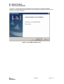
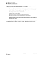
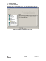
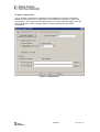
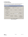
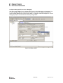
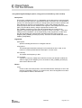
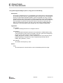
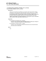
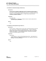
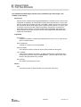
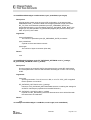
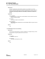
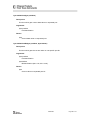
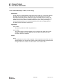
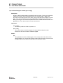
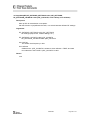
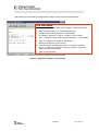
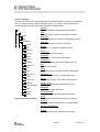
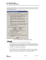
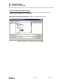
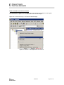
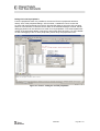
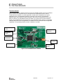
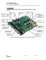
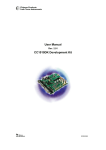
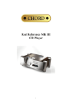
User Manual
Rev. 1.4
CC1010IDE Integrated Development Environment
SWRU057
Table of contents
INTRODUCTION ....................................................................................................................... 3
DOCUMENTATION ..................................................................................................................... 4
ABBREVIATIONS / DEFINITIONS .................................................................................................. 4
BASIC CC1010IDE ASSOCIATIONS ........................................................................................... 6
INSTALLING THE CC1010IDE ................................................................................................ 7
SETTING UP A SOFTWARE PROJECT FOR THE CC1010 ................................................ 11
CONFIGURE TARGET PROFILE .................................................................................................. 11
CONFIGURE MEMORY AND CLOCK PROFILE ............................................................................... 14
CONFIGURE OUTPUT PROFILE.................................................................................................. 15
CONFIGURE DEBUG PROFILE (IN-CIRCUIT DEBUGGER)............................................................... 17
CC1010 CODE INSPECTION AND TESTING ....................................................................... 18
DEBUGGER OPERATION .......................................................................................................... 18
SIMULATOR OPERATION .......................................................................................................... 18
LIBRARIES AND EXAMPLES................................................................................................ 19
HARDWARE DEFINITION FILES (HDF) ...................................................................................... 20
HARDWARE ABSTRACTION LIBRARY (HAL) .............................................................................. 20
CHIPCON UTILITY LIBRARY (CUL) ........................................................................................... 20
HAL LIBRARY REFERENCE ...................................................................................................... 21
CUL LIBRARY REFERENCE ...................................................................................................... 39
APPLICATION EXAMPLES ......................................................................................................... 48
GENERIC EXAMPLES ............................................................................................................... 52
UTILITIES................................................................................................................................ 53
FLASH PROGRAMMER ............................................................................................................. 53
SMARTRF® STUDIO ............................................................................................................... 55
MAINTENANCE ...................................................................................................................... 56
UPGRADES ............................................................................................................................ 56
SUPPORT ............................................................................................................................... 56
TUTORIAL............................................................................................................................... 57
BUILD A CC1010 SOFTWARE APPLICATION .............................................................................. 57
WRITE APPLICATION TO THE CC1010 (WITHOUT DEBUG OPTION) .............................................. 63
WRITE DEBUG MONITOR TO THE CC1010 ................................................................................ 64
DEBUG THE CC1010 CODE..................................................................................................... 65
DEBUG THE CC1010 PERIPHERALS ......................................................................................... 66
EVALUATING THE CC1010 PERFORMANCE ..................................................................... 67
DISCLAIMER .......................................................................................................................... 70
SWRU057
Introduction
The Integrated Development Environment (IDE) supports development, debugging and
simulation of CC1010 software applications and includes a project manager GUI, text editor,
simulator and debugger GUIs, and a compiler/assembler/linker. The CC1010IDE is based on
“uVision2”, a software development tool from Keil ™ Elektronik GmbH. This tool provides a
framework for most of the CC1010IDE features and it also supports most 8051
microcontroller platforms.
The editor is primarily a tool for editing source and assembler files. However, it also provides
syntax highlighting and other helpful functionality, such as GUI, needed for
simulation/debugging (disassembly, register dumps, memory dumps, watch windows,
instruction stepping, etc.). In addition, the IDE provides the interfaces towards the DLL used
for simulation and in-circuit debugging.
Since the compiler/assembler/linker is integrated in the development platform, the IDE in
effect ‘hides’ the invocation of these tools. More specifically the compiler converts one or
more C source files into assembly code, which, together with any handwritten assembler files
are fed to the assembler. The assembler then produces object files (machine code and binary
data), which in turn are fed into the linker together with any precompiled libraries. Finally, the
linker isolates functions and variables that are actually used and produces an executable file
in Intel HEX format that can be downloaded into the FLASH memory of a CC1010.
SWRU057
Page 3 of 70
Documentation
In addition to the files related to the use and functionality of the CC1010, the CC1010IDE
includes a set of documentation files (i.e.: CC1010DK User Manual), that provide details of
the CC1010 platform. The CC1010IDE documentation and software files are specified in later
chapters and distributed as follows (shaded boxes indicate location of the Chipcon files):
ASM
Hardware definitions for 8051 and other microcontrollers.
Keil
C51
BIN
Keil ™ program files, i.e.: compiler, linker, etc.
CC1010 debug extensions (DLL’s).
ASM
BIN
EXAMPLES(+)
CC1010 application examples + generic examples.
EXAMPLES (+)
HLP
Keil ™ help documents (compiler help, syntax help, etc).
HLP
INC (+)
INC(+)
Header files for CC1010 and other supported platforms.
ISD51 (+)
LIB (+)
CC1010DebugMon
ISD51(+)
In System Debugger provided by Keil ™.
LIB (+)
Keil ™ library files, i.e.: RS232 adapted dialog functions.
Chipcon libraries (HDF, HAL and CUL).
MON51
MON390 (+)
MON390(+)
Debug monitor for Dallas CPU.
RtxTiny2 (+)
DATASHTS
MON51
Keil ™ library files for the debug monitor.
Chipcon
RtxTiny2(+)
Tiny real time operating system provided by Keil ™, including
task scheduler, etc.
UV2
Figure 1: Software.
CC1010DebugMon
CC1010 debug monitor (target/embedded debug driver).
Program Files
DATASHTS
CC1010 documentation, i.e.: user manuals.
Chipcon
Documentation
UV2
Keil ™ uVision2 IDE program files (including device
database).
Flash Programmer
SmartRF Studio
Figure 2: Documentation
Documentation
Chipcon documentation, datasheets, etc.
Flash Programmer
CC1010 flash programmer.
SmartRF® Studio
SmartRF® Studio (tool for RF performance evaluation).
Abbreviations / Definitions
CC1010IDE
CC1010 Integrated Development Environment
SWRU057
Page 4 of 70
CC1010EB
CC1010DK
CC1010DS
CUL
DLL
HAL
HDF
ICD
IDE
RF
UV2
CC1010 Evaluation Board
CC1010 Development Kit
CC1010 Data Sheet
Chipcon Utility Library
Dynamic-Link Library
Hardware Abstraction Library
Hardware Definition Files
In-Circuit Debugger
Integrated Development Environment
Radio Frequency
Keil ™ uVision2
SWRU057
Page 5 of 70
Basic CC1010IDE associations
In order to provide a complete development environment the CC1010IDE integrates with a
number of other components. In addition to the application source code, it associates with
source libraries, documentation and DLL’s, and uses the serial port and parallel port to
download/communicate with the CC1010 embedded software:
Application:
RS232 modem,
Temperature sensor,
etc.
Parallel Port Interface:
Parallel port driver,
SPI programming DLL,
Stand-alone
SPI programming utility
Embedded SW (HEX-file):
Application,
SmartRF Studio Adapter,
Serial Port Debug Monitor
CC1010IDE Core:
Libraries:
Standard C,
HDF, HAL, CUL
Documentation:
CC1010 DK User Manual,
CC1010 DS Data Sheet,
etc.
GUI,
Editor,
Compiler,
Assembler,
Linker,
Debugger,
Simulator,
SmartRF Studio,
Flash programmer
Serial Port Interface:
In-circuit Debugger DLL
Simulator DLL
Figure 3: Basic CC1010IDE associations.
SWRU057
Page 6 of 70
Installing the CC1010IDE
The CC1010IDE integrates closely with Keil ™ uVision2 IDE. Hence in order for the
CC1010IDE modules to work Keil ™ uVision2 must be installed on the computer first,
otherwise the CC1010IDE installation will throw the following error message:
Figure 4: CC1010IDE installation check.
SWRU057
Page 7 of 70
Once Keil ™ uVision2 IDE has been installed successfully the CC1010IDE installation
program will automatically detect/recognize it on the computer and allow the user to proceed
with the CC1010IDE installation.
Figure 5: CC1010IDE installation start.
SWRU057
Page 8 of 70
The CC1010IDE installation covers multiple components that can be selected based on
individual needs. However, a default installation profile is used unless specified otherwise. To
change the suggested profile, just browse the ‘Select Components’ dialog and select/deselect
components as you prefer:
Figure 6: CC1010IDE installation components.
SWRU057
Page 9 of 70
Please note that the evaluation version of Keil ™ uVision2 accompanying the CC1010IDE
distribution imposes certain restrictions/limitation on the compiler:
•
PK51/C51 Compiler:
•
The 8051 compiler, assembler, linker, and debugger are limited to 2 Kbytes of object
code but source code can be any size. Programs generating more than 2 Kbytes of
object code will not compile, assemble, or link.
•
The debugger supports 2 Kbyte files or smaller.
•
Programs begin at offset 0x0800.
•
No hardware support is available for multiple DPTR registers.
•
No support is available for user libraries or floating point arithmetic.
•
The following Code Banking Linker, Library Manager and RTX-51 Tiny Real-Time
Operating System, which are present in the PK51 Full Version, are not included in the
PK51/C51 Eval Version.
•
It is not possible to generate assembler source files or use in-line assembler features.
For general limitations on the Keil ™ uVision2 compiler, please refer to C51 User’s Guide.
SWRU057
Page 10 of 70
Setting up a software project for the CC1010
Before the CC1010IDE can generate any target software it needs a software project with
consistent references to the actual target platform. These references can be specified in the
target configuration dialog.
Configure target profile
The initial step of target configuration is device association; right-click on ‘Target’ (CC1010)
and choose ‘Select device for target’. Then browse the Chipcon folder and associate a device
profile with the desired operation mode. For normal CC1010 run-time operation, just choose
‘CC1010’. To configure the CC1010 device for debug operation, however, choose
‘CC1010_debug’. This will dedicate specific memory ranges in the CC1010 RAM/ROM to the
so-called debug monitor, an embedded software module that drives the debug process (i.e.:
instruction stepping) on the CC1010 based on commands from the CC1010IDE (via RS232).
Note that the evaluation version of Keil ™ IDE does NOT support ‘Extended Linker…’:
Figure 7: CC1010 device profile for Keil ™ - evaluation version.
SWRU057
Page 11 of 70
Remember to always choose ‘Extended Linker…’ when using the full version of Keil ™ IDE:
Figure 8: CC1010 device profile for Keil ™ - full version.
SWRU057
Page 12 of 70
After choosing the desired device profile, right-click on ‘Target’ (CC1010) and choose
‘Options for Target CC1010’:
Figure 9: Target options.
SWRU057
Page 13 of 70
Configure memory and clock profile
Choose the ‘Target’ tab to configure the memory and clock profile for the CC1010 target.
Basically, the CC1010 is driven by an oscillator and it supports on-chip ROM/XRAM. For
debug operation it is necessary to allocate some memory for the debug monitor (as a result
the target will offer slightly less ROM/RAM space for the CC1010 application). Thus to enable
CC1010 debugging, ensure that the options ‘Use On-Chip ROM/XRAM’ are selected. For
consistency, please refer to following recommendation:
Figure 10: Memory and clock profile.
SWRU057
Page 14 of 70
Configure output profile
The CC1010IDE “build process” generates an executable file according to the settings
specified in the ‘Output’ tab. To support the CC1010 target the output file must be in the
correct format. The ‘Output’ tab also offers options to run user-specified programs after the
output file has been made. In general Chipcon recommends the following output
configuration:
Figure 11: Output profile.
SWRU057
Page 15 of 70
In addition to the executable file the CC1010IDE can also produce a variety of list files, i.e.: to
support inspection/debugging of the target code. In order to generate a full inspection
reference to the target code the following listing configuration is recommended:
Figure 12: Listing profile.
SWRU057
Page 16 of 70
Configure debug profile (in-circuit debugger)
The ‘Debug’ tab enables you to configure the CC1010 in-circuit debugger and simulator. The
in-circuit debugger supports remote run-time control of the CC1010 software and requires
communication between the PC and CC1010EB. To configure the CC1010 target for in-circuit
debugging Chipcon recommends the following configuration:
Figure 13: Debug profile.
SWRU057
Page 17 of 70
CC1010 Code inspection and testing
To inspect and test the target software CC1010IDE includes powerful tools for in-circuit
debugging and limited target simulation.
Debugger operation
The CC1010 in-circuit debugger consists of a uVision2 plug-in DLL, that communicates with a
hidden 8051 program through a serial cable. With a few exceptions, it is completely
transparent for the user:
•
•
•
•
•
•
•
It is impossible to step into an interrupt (use breakpoints instead).
It is impossible to stop inside a high priority interrupt (use breakpoints instead).
The CC1010 should only be reset through the debugger.
Idle and sleep mode should be avoided.
The watchdog timer will be disabled.
C-code steps are done through several assembly code steps (a progress bar is
displayed in the uVision2 status bar). Expected performance: 30-40 ASM
steps/second.
The LJMP instruction at address 0 is moved to a reserved address at page 0. The
move is hidden by the debugger plug-in.
For text boxes in the debugger dialogs:
•
•
Press ‘ENTER’ to write the value to the target (CC1010).
Exit the text box to undo an entry: If the user activates a different dialog before
pressing ‘ENTER’ the current values in the text box is replaced by old values
Resources used on CC1010:
•
•
•
•
UART 1
Stack: 4 bytes
Xdata: 22 bytes
Flash: > 2k bytes
The following procedure is required for CC1010 debugging:
•
•
•
•
•
•
•
Connect parallel cable between PC and CC1010EB.
Connect serial cable between PC and CC1010EB (‘SERIAL 1’).
On CC1010EB, make sure the SER_RST jumper is shorted and the SER_OFF
jumper is open.
Make sure the right debugger plug-in/driver is selected in Keil:
’Project->Options for Target->Debug->Use=Chipcon CC1010 In-System Debugger’
Make sure the right PC serial port is selected for the debugger plug-in/driver in Keil:
’Project->Options for Target->Debug->Settings’.
In the IDE choose ‘Tools->Write Debug Bootloader To CC1010 Flash’ to download
the debug bootloader to CC1010. This prepares CC1010 for debugging.
In the IDE choose ‘Debug->Start/Stop Debug Session’ to start debugging. The
debugger will then automatically download the application code to CC1010.
Simulator operation
Not available in this version.
SWRU057
Page 18 of 70
Libraries and examples
The CC1010IDE includes a variety of source files to ease and support the program
development. Besides the standard C libraries, the source/support files are divided into 4
main groups: Hardware Definition Files (HDF), Hardware Abstraction Library (HAL), Chipcon
Utility Library (CUL) and finally application examples. To examine these files in detail refer to
the Keil ™ program directory.
RS232-modem,
Temperature sensor, keyboard,
Nightrider, etc.
Application Examples
(source code)
Chipcon Utility Library
(CUL)
Standard C
Libraries
CRC, SPP, etc.
Hardware Abstraction Library
(HAL)
RS232, SPI, ADC, DES (crypto), etc.
Register definitions,
interrupt vector mapping, etc.
Hardware Definition Files
(HDF)
Figure 14: Library stack.
Keil
C51
ASM
BIN
EXAMPLES (+)
HLP
INC (+)
ISD51 (+)
LIB (+)
CC1010DebugMon
MON51
MON390 (+)
RtxTiny2 (+)
DATASHTS
Chipcon
UV2
Figure 15: Library files.
Library limitations
- Keil ™ Full version:
CUL and HAL are provided as libraries (.lib).
- Keil ™ Evaluation version:
User libraries are not supported.
Each individual HAL, CUL, files must be added
“manually” to each software project.
HDF overview (INC):
- Evaluation Board macros (i.e.: LED control).
- Register definitions (i.e.: special function registers).
- Control register definitions/macros.
- Interrupt macros (i.e.: vector assignments).
- Etc.
HAL overview (LIB):
- RF calibration, configuration, packet transfer, etc.
- Flash memory write.
- Timer configuration.
- ADC configuration.
- Port configuration.
- UART control/configuration.
- DES data encryption.
- Etc.
CUL overview (LIB):
- CRC checksum calculation.
- Simple Packet Protocol (SPP).
- Etc.
Application examples overview (EXAMPLES):
- Simple UART communication (echo function).
- RS232 modem communication.
- Etc.
SWRU057
Page 19 of 70
Hardware Definition Files (HDF)
The hardware definition files define register addresses, interrupt vector mapping and other
hardware constants. They also include useful macros for the CC1010EB, and all definitions
generally support both assembly and C language:
Application Examples
(source code)
Chipcon Utility Library
(CUL)
Standard C
Libraries
Hardware Abstraction Library
(HAL)
Hardware Definition Files
(HDF)
"CC1010EB.h" : LED_ON, LED_OFF, etc.
"Reg1010.h" : RFBUF, INUM_RF, etc.
Figure 16: Hardware Definition Files (HDF).
Hardware Abstraction Library (HAL)
To support quick and easy program development Chipcon provides a library of macros and
functions that simplify hardware access on the CC1010. These are located in the Hardware
Abstraction Library (HAL) and implement a hardware abstraction interface for the user
program. As a result the user program can access the microcontroller peripherals, etc. via
function/macro calls, without specific knowledge about the hardware details.
Application Examples
(source code)
Chipcon Utility Library
(CUL)
Standard C
Libraries
Hardware Abstraction Library
(HAL)
"HAL.h" : halRFSendPacket(...), etc.
Hardware Definition Files
(HDF)
Figure 17: Hardware Abstraction Library (HAL).
Chipcon Utility Library (CUL)
Besides the HAL module the CC1010IDE also provides a library of RF communication
building blocks located in the Chipcon Utility Library (CUL). This library offers useful support
for typical RF applications and, eventually it will provide a full RF protocol.
Application Examples
(source code)
Chipcon Utility Library
(CUL)
Standard C
Libraries
"CUL.h" : culCRC16(...), sppReceive(...), etc.
Hardware Abstraction Library
(HAL)
Hardware Definition Files
(HDF)
Figure 18: Chipcon Utility Library (CUL).
SWRU057
Page 20 of 70
HAL library reference
void halConfigADC(byte options, word clkFreq, byte threshold)
Description:
This function configures the ADC.
An interrupt is generated in all modes (except for reset-generating mode in which a
reset is generated instead) whenever the 8 MSB of the measured sample is greater
or equal to the threshold value. Thus, if an interrupt for each sample is desired, the
threshold should be set to 0 (and the ADC and GLOBAL_ADC_DES interrupts
enabled.) After configuring the ADC it must be powered up using the
ADC_POWER(bool) macro. It should be powered down again when not in use to
conserve power. The correct ADC input must be selected using the
ADC_SELECT_INPUT(input) macro and started using the ADC_RUN(bool) macro for
continuous modes. The ADC_SAMPLE_SINGLE macro is used to initiate a sample
acquisition in single-conversion mode, and the ADC_RUNNING macro can be used
to determine whether the sample is complete The ADC_GET_SAMPLE_10BIT or
ADC_GET_SAMPLE_8BIT macros return the latest sample value.
Arguments:
byte options
Selects operational mode
word clkFreq
The XOSC clock frequency in kHz.
byte threshold
The threshold value for generating interrupts (and stopping in multi-conversion,
stopping mode) or reset (in multi-conversion, reset-generating mode).
Return:
void
SWRU057
Page 21 of 70
void halConfigRealTimeClock(byte period)
Description:
This function configures the realtime clock. In order for the realtime clock to function
the 32 kHz oscillator must be connected to a 32 kHz crystal or a 32 kHz clock signal
must be available on pin XOSC32_Q1. The 32 kHz oscillator must be started up and
stable before the RTC is activated. The realtime clock must be started by using the
macro RTC_RUN(TRUE).
Arguments:
byte period
The desired period between interrupts in seconds.
Return:
void
SWRU057
Page 22 of 70
ulong halConfigTimer01(byte options, ulong period, word clkFreq, word* modulo)
Description:
This function configures timer 0 or 1 (depending on the value given in option as either
an interrupt timer (an interrupt is generated at certain intervals in time, as specified by
period) or an interrupt pulse counter (an interrupt when period number of pulses have
been detected on P3.4/P3.5 for timer0/timer1.) Some timer settings (with long
timeouts) require that the user initializes timer register in the interrupt service routine
(ISR.) This should be done by using the appropriate version of the
ISR_TIMERx_ADJUST(m) macro with the word pointed to by modulo as an
argument. The modulo argument takes a pointer to a word, if it is NULL, many timer
settings will be unavailable. It is the responsibility of the programmer to make sure
that the appropriate timer ISR has been declared (and that it begins with the
obligatory ISR_TIMERx_ADJUST(m) macro). The timer must be started with macro
TIMERx_RUN(TRUE).
Arguments:
byte options
Options indicating which timer to configure and how.
ulong period
The desired period between interrupts in microseconds in timer mode, or the
number of counted pulses between interrupts in counter mode.
word clkFreq
The XOSC clock frequency in kHz.
word* modulo
A pointer to a word (in xdata) which after the function has returned contains the
value to supply to the obligatory macro invocation of ISR_TIMERx_ADJUST(m)
at the start of the timer ISR.
Return:
ulong
In timer mode, the actual period in microseconds between interrupts or zero if the
period is impossible to achieve. In counter mode, zero if the supplied count value
is impossible to achieve, otherwise one.
SWRU057
Page 23 of 70
ulong halConfigTimer23(byte options, ulong period, word clkFreq)
Description:
This function configures timer 2 or 3 (depending on the value given in option as either
an interrupt timer (an interrupt is generated at certain intervals in time, as specified by
period) or a pulse width modulator (PWM). If period is specified as 0, then, in timer
mode the timeout period will be set to the maximum possible, and in PWM mode the
period will be set as long as possible. Using the PWM mode of timer 2/3 overrides the
normal operation of ports P3.4/P3.5 and can thus not be used in conjunction with
timer 0/1 configured as counters. The duty cycle is set to 50% (128/255) initially in
PWM mode. The timer/PWM must be started with macro TIMERx_RUN(TRUE).
Arguments:
byte options
Options indicating which timer to configure and how.
ulong period
The desired period between interrupts in microseconds. In PWM mode the duty
cycle will be set as close to 50% as possible. This duty cycle can be changed (in
an ISR or at any other time) by using the appropriate
PWMx_SET_DUTY_CYCLE(...) macro. If period is 0, then the maximum period
possible will be set. The period can also be adjusted dynamically with the
PWMx_SET_PERIOD(...) macro.
word clkFreq
The XOSC clock frequency in kHz.
Return:
ulong
The actual period in microseconds or zero if the desired period is too high.
SWRU057
Page 24 of 70
bool halCopy2Flash(byte code* flashPtr, byte* src, word length, byte xdata* ramBuffer,
word clkFreq)
Description:
Copies length bytes from the memory area pointed to by src (in any memory space)
to the memory area in CODE memory space pointed to by flashPtr. A 128 byte
temporary buffer in the XDATA memory space must be pointed to by ramBuffer.
None of the pointers (flashPtr, src or ramBuffer) need to be page-aligned (address
mod 128=0) as with halFlashWritePage(...), neither does length have to be a multiple
of 128 bytes -- it can in fact be between 1 and 32768 bytes, although it goes without
saying that it is unwise to overwrite the memory occupied by the code for this
function. The result is undefined if the memory areas occupied by [src, src+length-1]
and [ramBuffer, ramBuffer+127] overlap. A verification of the data written is
performed after programming – if this verification fails for some reason (flash page is
write locked, flash programming failure) or some of the supplied arguments are
invalid the function returns FALSE. All interrupts are turned off while this function
executes.
Arguments:
byte code* flashPtr
Pointer to the destination of the write in code memory space.
byte* src
Pointer to the data source.
word length
The number of bytes to copy.
byte xdata* ramBuffer
A pointer to a 128 byte big buffer in XDATA memory space used to hold
temporary data.
word clkFreq
The XOSC clock frequency in kHz.
Return:
bool
TRUE if the write was successful. False if programming/verification failed or the
supplied arguments were invalid.
SWRU057
Page 25 of 70
byte* halDES(byte options, byte xdata* buffer, byte xdata* key, word length)
Description:
This function performs DES encryption/decryption on a block of data. The
encryption/decryption operations are performed in place (i.e. the plaintext is
overwritten by the ciphertext or vice versa) on suitably aligned data [ address(buffer)
mod 8 = 0 ]. key should point to the key used for single-DES operations or keys in the
case of triple-DES. Two modes of the DES standard are supported: 8-bit Cipher
Feedback (CFB) and Output Feedback (OFB.) CFB is self-synchronizing (the end of
a ciphertext can be decrypted even though the beginning is unavailable) and can be
used to calculate error check codes. OFB is not self- synchronizing and is not
suitable for error check code calculation, but does have the favorable property that a
single bit error in the received ciphertext produces only a single bit error in the
decrypted plaintext. In CFB/OFB mode an initialization vector of 8 bytes is part of the
algorithm. This vector must be identical for the encryption and decryption process.
The choice of initialization data does not affect the security of the encryption in any
way, and this function thus uses the value 0. option is used to chose between these
modes of operation, between single-DES and triple-DES, and between decryption
and decryption. This function does not return until all data has been encrypted/
decrypted, since the DES hardware is so fast. The DES hardware can run at the
same time as the 8051 and generate an interrupt when finished. If this is desired the
hardware must be programmed directly.
Arguments:
byte options
One or more of the below defined constants define the desired operational mode:
DES_SINGLE_DES, DES_TRIPLE_DES, DES_ENCRYPT, DES_DECRYPT,
DES_OFB_MODE, DES_CFB_MODE.
byte xdata* buffer
Pointer to the data to encrypt/decrypt in XDATA memory space. The address of
buffer must be divisible by eight, i.e. address(buffer) mod 8 = 0.
byte xdata* key
A pointer to a key (or three keys for triple-DES) stored in XDATA memory space.
This address must be divisible by eight, i.e. address(key) mod 8 = 0. The 56
active bits of a DES-key are expected to be in a compressed 7-byte format, in
which all parity bits are removed. In the case of a single key, the 56 bits of the
key must lie on key[0] - key[6], in big-endian order. In the case of three keys
(triple-des), the three keys must lie on key[0] - key[6], key[8] - key[14] and key[16]
- key[22], all in big-endian order. DES_NORMAL_2_COMPACT_KEY(...) can be
used to convert a regular DES key to the compact form. A key can be generated
by simply using 7 random bytes.
word length
The number of bytes to perform the encryption/decryption on
Return:
byte*
A pointer to the start of buffer is returned.
SWRU057
Page 26 of 70
bool halFlashWritePage(byte code* flashPage, byte xdata* ramBuffer, word clkFreq)
Description:
Writes into the flash page pointed to by flashPage 128 bytes of data pointed to by
ramBuffer. The addresses of both flashPage and ramBuffer must be an integer
multiple of 128, i.e. adr mod 128=0. clkFreq must be the XOSC frequency in kHz and
is used to calculate the correct erasure and programming times. If these conditions
are not met the function does not perform any programming and returns FALSE. A
verification of the data written is performed after programming - if this verification fails
for some reason (flash page is write locked, or flash programming failure) the function
also returns FALSE. All interrupts are turned off while this function executes.
Arguments:
byte code* flashPage
Pointer to the destination of the write in code memory space. Address must be an
integer multiple of 128 bytes.
byte xdata* ramBuffer
Pointer to the data source in RAM for the write in XDATA memory space.
Address must be an integer multiple of 128 bytes.
word clkFreq
The XOSC clock frequency in kHz.
Return:
bool
TRUE if the write was successful. False if programming/verification failed or
supplied arguments were invalid.
SWRU057
Page 27 of 70
void halRandomNumberGen(byte* rnd_data, word length)
Description:
This function activates the true RNG in the CC1010, waits long enough for the output
to be truly random and then samples individual random bits with a period that
ensures that the output is sufficiently random. This function must never be used at
the same time as RF is in use. A total of _length_ bytes of random data is stored at
the location pointed to by rnd_data.
Arguments:
byte* rnd_data.
A pointer to a buffer to receive the random bytes.
word length
The number of random bytes to generate.
Return:
void
SWRU057
Page 28 of 70
void halRFCalib(RF_RXTXPAIR_SETTINGS code* rf_settings,
RF_RXTXPAIR_CALDATA xdata* rf_caldata)
Description:
Performs the necessary RF-calibration for an RX/TX channel pair with the settings
specified by the RF_RXTXPAIR_SETTINGS data structure pointed to by rf_settings.
The results of the calibration are stored in the RF_RXTXPAIR_CALDATA data
structure pointed to by rf_caldata. Call this function once for each RX/TX channel pair
that will be used by the program before they are used and whenever the supply
voltage or temperature has changed significantly. The application Chipcon SmartRF®
Studio should be used to generate this data structure.
Arguments:
RF_RXTXPAIR_SETTINGS code* rf_settings
Pointer to a RF_RXTXPAIR_SETTINGS data structure containing the settings for
an RX/TX channel pair (exported from SmartRF® Studio.)
RF_RXTXPAIR_CALDATA xdata* rf_caldata
A pointer to a RF_RXTXPAIR_CALDATA data structure which will be filled with
the results from the calibration.
Return:
void
SWRU057
Page 29 of 70
void halRFOverrideDataFormat(byte dataFormat)
Description:
Function used to override the data format (normally specified by an RX/TX-pair). If
this function is called before halRFSetRxTxOff(...) it uses the parameter passed to
this function instead of whatever the RX/TX-pair defines. If it is passed during an RFoperation, i.e. after halRFSetRxTxOff(...) is called, the parameter passed is
immediately updated in hardware.
Arguments:
byte dataFormat
RF data format. To disable the override the function must be called with the
parameter RF_NO_OVERRIDE.
Return:
void
void halRFOverrideOutputPower(byte txPower)
Description:
Function used to override the RF TX output power (normally specified by an RX/TXpair). If this function is called before halRFSetRxTxOff(...) it uses the parameter
passed to this function instead of whatever the RX/TX-pair defines. If it is passed
during an RF-operation, i.e. after halRFSetRxTxOff(...) is called, the parameter
passed is immediately updated in hardware.
Arguments:
byte txPower
A value between 1 and 28 indicates desired power level -- 28 is highest and 1
lowest. Some useful constants are defined below. The override is turned off by
passing 0 or RF_NO_OVERRIDE.
Return:
void
SWRU057
Page 30 of 70
void halRFOverrideBaudRate(byte baudRate)
Description:
Function used to override the baudrate (normally specified by an RX/TX-pair). If this
function is called before halRFSetRxTxOff(...) it uses the parameter passed to this
function instead of whatever the RX/TX-pair defines. If it is passed during an RFoperation, i.e. after halRFSetRxTxOff(...) is called, the parameter passed is
immediately updated in hardware. Note that for optimal performance, the baudrate
can only be changed without a new calibration within the two sets (600, ..., 19200)
and (38400, 76800).
Arguments:
byte dataFormat
To disable the override the function must be called with the parameter
RF_NO_OVERRIDE.
Return:
void
SWRU057
Page 31 of 70
char halRFReadRSSI()
Description:
This function activates RSSI output on the AD2 pin, activates the ADC for channel 2
reads, the RSSI output voltage and converts it to an approximation of the incoming
signal's strength in dBm (range is appr. -110 to -50 dBm.) The value obtained is
approximate and most valid for a signal @ 600 MHz. The accuracy should be no
worse than +/- 10 dBm at any frequency. An RSSI filter circuit of one capacitor and
one resistor is required to be connected to the AD2 pin externally (see datasheet for
details). This function disrupts user ADC operation and does not restore the ADC to
its former state. The function can be used as a carrier sense if the returned value is
compared to some relatively low threshold.
Arguments:
void
Return:
char
The approximate signal strength of the incoming signal in dBm.
SWRU057
Page 32 of 70
byte halRFReceivePacket(byte timeOut, byte* packetData, byte maxLength, char*
rssiByte, word clkFreq)
Description:
Used to receive a packet sent using halSendPacket on another CC1010. The current
modem/RF configuration is used and RX is assumed to be powered up. The function
waits for a valid syncronization byte (RF_SUITABLE_SYNC_BYTE) for up to timeOut
ms. If timed out without receiving the sync. byte the function returns 0. If a sync. byte
is received in time the number of bytes indicated by the packet is received (max
maxLength bytes) and put in the buffer pointed to by packetData, after which the
function returns the number of bytes received. THIS FUNCTION ASSUMES THAT
TIMER3 IS AVAILABLE!
Arguments:
byte timeOut
Timeout for reception of valid synchronization byte in tens of ms. A value of zero
gives an infinite timeout.
byte* packetData
A pointer to a buffer for the received data.
byte maxLength
The maximum number of bytes to receive (max packet size 253 bytes).
char* rssiByte
If this pointer is different from NULL an RSSI measurement is performed after
receiving the sync byte using the halReadRSSI(...) function and its return value
stored in the byte pointed to by rssiByte.
word clkFreq
The XOSC clock frequency in kHz.
Return:
byte
The actual number of bytes received or 0 if timed out / CRC error.
SWRU057
Page 33 of 70
void halRFSendPacket(byte numPreambles, byte* packetData, byte length)
Description:
Used to send a packet using the current RF configuration. (It is assumed that
halRFSetRxTxOff(...) has been called with the appropriate RX/TX pair and mode
RF_TX.) First numPreambles preamble bytes (RF_PREAMBLE_BYTE) are
transmitted followed by a synchronization byte (RF_SUITABLE_SYNC_BYTE), the
length byte, the data pointed to by packetData (length bytes) and then, finally, the
CRC-16 (CCITT) of the data.
Arguments:
byte numPreambles
The number of preamble bytes (RF_PREAMBLE_BYTE) to transmit.
byte* packetData
A pointer to the actual data to transmit.
byte length
The number of bytes to transmit. (Max 253)
Return:
void
void halRFSetRxTxOff(byte mode, RF_RXTXPAIR_SETTINGS code* rf_settings,
RF_RXTXPAIR_CALDATA xdata* rf_caldata)
Description:
Function used to set a specific RX/TX channel pair as the current RF configuration.
The mode parameter is used to select between activating RF in RX or TX or turning
off RF.
Arguments:
byte mode
Options given below. Turn off, turn on in RX, or on in TX. If RF_OFF is supplied
the two pointers can be NULL.
RF_RXTXPAIR_SETTINGS code* rf_settings
Pointer to a RF_RXTXPAIR_SETTINGS data structure containing the settings for
an RX/TX channel pair (exported from SmartRF® Studio.)
RF_RXTXPAIR_CALDATA xdata* rf_caldata
A pointer to a RF_RXTXPAIR_CALDATA data structure which will be filled with
the results from the calibration.
Return:
void
void halSpiTransferBlock(byte* inoutBuffer, word length, bool enableRead)
SWRU057
Page 34 of 70
Description:
Transfers length bytes of the data block pointed to by inoutBuffer over the SPI
interface. It is assumed that the SPI interface has already been correctly configured.
If read is TRUE the incoming data on the SPI interface will be stored in place in
inoutBuffer, (overwriting the data that is transmitted), otherwise the received data is
ignored.
Arguments:
byte* inoutBuffer
Pointer to a block of data that is to be transmitted. If read is TRUE the received
data will overwrite this data.
word length
The number of bytes to receive/transmit.
bool enableRead
Overwrite the data transmitted with the received data (TRUE) or ignore received
data (FALSE).
Return:
void
void halWait(byte timeOut, word clkFreq)
Description:
A wait functions which performs a number of iterations of a simple wait loop, so that
at least timeOut ms goes by before the function returns.
Arguments:
byte timeOut
The time to wait in ms.
word clkFreq
The XOSC clock frequency in kHz.
Return:
void
SWRU057
Page 35 of 70
void halSetPort(byte portNum, byte dataByte)
Description:
Function which sets data for an entire port.
Arguments:
byte portNum
Port identification.
byte dataByte
Data value to be placed on the requested port.
Return:
void
void halSetPortBit(byte portNum, byte bitNum, byte dataBit)
Description:
Function which sets port data bitwise.
Arguments:
byte portNum
Port identification.
byte bitNum
Bit identification (bit0 = lsb, bit7 = msb).
byte dataBit
Data value to be placed on requested port bit.
Return:
void.
SWRU057
Page 36 of 70
void halSetPortBitDir(byte portNum, byte bitNum, byte direction)
Description:
Function which sets the direction (in/out) for one specific port bit.
Arguments:
byte portNum
Port identification
byte bitNum
Bit identification (bit0 = lsb, bit7 = msb).
byte direction
Port direction (in = 1, out = 0).
Return:
void
void halSetPortDir(byte portNum, byte direction)
Description:
Function which sets the direction for an entire port.
Arguments:
byte portNum
Port identification.
byte direction
Port direction (in = 1, out = 0).
Return:
void
SWRU057
Page 37 of 70
byte halGetPort(byte portNum)
Description:
Function which gets current data value on requested port.
Arguments:
byte portNum
Port identification.
Return:
byte
Current data value on requested port.
byte halGetPortBit(byte portNum, byte bitNum)
Description:
Function which gets the current value on one specific port bit.
Arguments:
byte portNum
Port identification.
byte bitNum
Bit identification (bit0 = lsb, bit7 = msb).
Return:
byte
Current value on requested port bit.
SWRU057
Page 38 of 70
CUL library reference
byte culSmallCRC8(byte crcData, byte crcReg)
Description:
A CRC-8 (DOW) implementation optimized for small code size. The function should
be called once for each byte in the data the CRC is to be performed on. For the
invocation on the first byte the value CRC8_INIT should be given for crcReg. The
value returned is the CRC-8 of the data supplied so far. This CRC-value should be
added at the end of the data to facilitate a later CRC check. During checking the
check should be performed on all the data AND the CRC-16 value appended to it.
The data is intact if the value returned is 0.
Arguments:
byte crcData
The data to perform the CRC-8 operation on.
byte crcReg
The current value of the CRC register. For the first byte the value CRC8_INIT
should be supplied. For each additional byte the value returned for the last
invocation should be supplied.
Return:
byte
The updated value of the CRC8 register. This corresponds to the CRC-8 of the
data supplied so far. During CRC checking, after working through all the data and
the appended CRC-8 value, the value will be 0 if the data is intact.
SWRU057
Page 39 of 70
word culSmallCRC16(byte crcData, word crcReg)
Description:
A CRC-16/CCITT implementation optimized for small code size. The function should
be called once for each byte in the data the CRC is to be performed on. For the
invocation on the first byte the value CRC16_INIT should be given for crcReg. The
value returned is the CRC-16 of the data supplied so far. This CRC-value should be
added at the end of the data to facilitate a later CRC check. During checking the
check should be performed on all the data AND the CRC-16 value appended to it.
The data is intact if the value returned is 0.
Arguments:
byte crcData
The data to perform the CRC-16 operation on.
word crcReg
The current value of the CRC register. For the first byte the value CRC16_INIT
should be supplied. For each additional byte the value returned for the last
invocation should be supplied.
Return:
word
The updated value of the CRC16 register. This corresponds to the CRC-16 of the
data supplied so far. During CRC checking, after working through all the data and
the appended CRC-16 value, the value will be 0 if the data is intact.
SWRU057
Page 40 of 70
byte culFastCRC8(byte crcData, byte crcReg)
Description:
A CRC-8 (DOW) implementation optimized for fast execution. The function should be
called once for each byte in the data the CRC is to be performed on. Before the
invocation on the first byte the FAST_CRC8_INIT() macro should be called. This final
CRC-value should be added at the end of the data to facilitate a later CRC check.
During checking the check should be performed on all the data AND the CRC-8 value
appended to it. The data is intact if the value returned is 0.
Arguments:
byte crcData
The data to perform the CRC-8 operation on.
byte crcReg
The current value of the CRC register. For each additional byte the value
returned for the last invocation should be supplied.
Return:
byte
The updated value of the CRC8 register. This corresponds to the CRC-8 of the
data supplied so far. During CRC checking, after working through all the data and
the appended CRC-8 value, the value will be 0 if the data is intact.
SWRU057
Page 41 of 70
word culFastCRC16(byte crcData, word crcReg)
Description:
A CRC-16 (CCITT) implementation optimized for fast execution. The function should
be called once for each byte in the data the CRC is to be performed on. Before the
invocation on the first byte the FAST_CRC16_INIT() macro should be called. This
final CRC-value should be added at the end of the data to facilitate a later CRC
check. During checking the check should be performed on all the data AND the CRC16 value appended to it. The data is intact if the value returned is 0.
Arguments:
byte crcData
The data to perform the CRC-16 operation on.
word crcReg
The current value of the CRC register. For each additional byte the value
returned for the last invocation should be supplied.
Return:
word
The updated value of the CRC16 register. This corresponds to the CRC-16 of the
data supplied so far. During CRC checking, after working through all the data and
the appended CRC-16 value, the value will be 0 if the data is intact.
SWRU057
Page 42 of 70
byte sppReceive (SPP_RX_INFO xdata *pRXInfo)
Description:
If the transceiver is ready (in idle mode), the receive section will be powered up and
the RF interrupt enabled. The RF ISR will then receive the packet and transmit an
ack if requested to. When finished, the receive section will be powered down. This
function will return immediately and the application can continue while the ISR
receives the packet. When finished, sppStatus() will return IDLE_MODE. During the
transmission it will return RX_MODE or RXACK_MODE. After the reception: Use
pRXInfo->status to find out what happened:
SPP_RX_TIMEOUT = Timeout (nothing received).
SPP_RX_TOO_LONG = dataLen > maxDataLen (the buffer is invalid).
SPP_RX_FINISHED = source, dataLen and *pDataBuffer in *pRXInfo are valid.
Arguments:
SPP_RX_INFO xdata *pRXInfo
An SPP_RX_INFO struct must be prepared before the reception, including the
following values:
maxDataLen (Length of the data buffer, 0-255)
DataBuffer (pointer to the reception buffer).
Return:
byte
SPP_RX_STARTED if OK
SPP_BUSY if not ready.
SWRU057
Page 43 of 70
byte sppSend (SPP_TX_INFO xdata *pTXInfo)
Description:
If the transceiver is ready (in idle mode), the transmit section will be powered up and
the RF interrupt enabled. The RF ISR will then transmit the packet (pTXInfo) and
receive the ack (if requested). If requested (sppSettings.txAttempts = n), the packet
will be re-transmitted (n-1) times, until the ack is received. When finished the transmit
section will be powered down. This function will return immediately and the
application can continue while the ISR transmits the packet. When finished,
sppStatus() will return IDLE_MODE. During the transmission it will return TX_MODE
or TXACK_MODE. After the transmission: Use pTXInfo->status to find out what
happened:
SPP_TX_ACK_INVALID = Something was received, but not the ack
SPP_TX_ACK_TIMEOUT = No response
SPP_TX_FINISHED
sppSettings.txAckTimeout gives the ack timeout in msecs.
Arguments:
SPP_TX_INFO xdata *pTXInfo
An SPP_TX_INFO struct must be prepared before the transmission, including the
following values:
destination (SPP_BROADCAST or 1-255)
flags (SPP_ACK_REQ | SPP_ENCRYPTED_DATA)
dataLen (Length of *pDataBuffer, 0-255)
pDataBuffer (pointer to the transmission data buffer).
Return:
byte
SPP_TX_STARTED if OK
SPP_BUSY if not ready
SWRU057
Page 44 of 70
void sppSetupRF (RF_RXTXPAIR_SETTINGS code *pRF_SETTINGS,
RF_RXTXPAIR_CALDATA xdata *pRF_CALDATA, word clkFreq, bool calibrate)
Description:
Sets up SPP for transmission or reception.
Call this function to (re)calibrate the radio, or to switch between different RF settings.
Arguments:
RF_RXTXPAIR_SETTINGS code* pRF_SETTINGS
RF settings (frequencies, modem settings, etc.).
RF_RXTXPAIR_CALDATA xdata* pRF_CALDATA
RF_RXTXPAIR_CALDATA xdata* pRF_CALDATA
word clkFreq
The XOSC clock frequency in kHz.
bool calibrate
Calibrate now. *pRF_CALDATA is written to when calibrate = TRUE, and read
from otherwise. Use FALSE if *pRF_CALDATA is valid.
Return:
void
SWRU057
Page 45 of 70
void sppReset (void)
Description:
Stops a transmission or reception by - turning the transceiver off - entering IDLE
mode (sppStatus()).
Arguments:
void.
Return:
void
byte sppStatus (void)
Description:
Returns the status of the SPP.
Arguments:
void
Return:
byte
SPP_IDLE_MODE = Ready to transmit or receive
SPP_TX_MODE = Transmitting a packet
SPP_TXACK_MODE = Waiting for the ack
SPP_RX_MODE = Waiting for or receiving a packet
SPP_RXACK_MODE = Transmitting the ack.
SWRU057
Page 46 of 70
void sppStartTimer (word clkFreq)
Description:
Run timer3 with a period of 10 msecs.
Arguments:
word clkFreq
The XOSC clock frequency in kHz.
Return:
void
void sppSetTimerCB (byte cb, void (*pF) (), word *pTicks
Description:
Add timer callback.
Arguments:
byte cb
Callback index - use SPP_CUSTOM_0_TIMER or SPP_CUSTOM_1_TIMER
The SPP finite state machine uses SPP_FSM_TIMER.
void *pF
Pointer to the function to call
word *pTicks
The timeout in 10s of msecs
Return:
void
word sppGetTime (void)
Description:
Returns the value of the 10-msec counter, which is started by sppSetupRF(...).
Arguments:
void
Return:
word
The current time in 10s of msecs.
SWRU057
Page 47 of 70
Application examples
The CUL, HAL and HDF enable the user to create applications based on a consistent and
tested software platform. To boost the application development process the CC1010IDE also
offers some useful application examples that demonstrate typical use/integration of the
libraries. In general these examples can be downloaded from Chipcon’s web site
(http://www.chipcon.com). Detailed documentation and explanation of the application
examples are available under the Chipcon documentation directory:
C:\Program Files\Chipcon.
Application Examples
(source code)
"temp_main.c" : tbcTransmit(...), etc.
Chipcon Utility Library
(CUL)
Standard C
Libraries
Hardware Abstraction Library
(HAL)
Hardware Definition Files
(HDF)
Figure 19: Chipcon application examples.
SWRU057
Page 48 of 70
The example below is typical of the way the Chipcon libraries can be used in an application
that enables terminal communication with the CC1010. This application example implements
a simple file transfer protocol on top of HAL, and uses a UART channel to communicate with
a terminal program on the PC. Note that parts of the source code, i.e.: dialog, have been
removed to highlight the core functionality:
Include libraries: HDF + HAL + Standard C
Call HAL macro
RX function
Call standard C functions
(Keil ™ adaptation for RS232)
TX function
Call HAL macro
Figure 20: Application example promoting typical integration of Chipcon libraries.
SWRU057
Page 49 of 70
After building and downloading the application example, follow the test procedure below:
Test procedure:
1. Connect a PC to CC1010EB, using crossed 0-modem serial cable.
2. Open terminal program (i.e.: hyperterminal) on PC.
3. Configure serial communication on COM1/COM2:
57.6 kbit/sec, 8 data bit, 1 stop bit, no parity, no flow control.
4. Type ’1’ and enter name of file to be transferred [PC -> CC1010EB].
5. Type ’2’ to prepare CC1010EB for file transfer.
Follow the instructions on the screen.
6. If the file transfer succeeded then option ’3’ becomes available.
type ’3’ to request CC1010EB to echo [CC1010EB -> PC] the file
characters it has just received.
7. Type ’9’ to end session.
Figure 21: Application example - test procedure.
SWRU057
Page 50 of 70
Type ‘2’ to transfer file from the PC to CC1010EB:
Figure 22: Application example – file transfer from PC to CC1010EB.
Type ‘3’ to transfer file from CC1010EB to the PC, then verify content:
Figure 23: Application example – file transfer from CC1010EB to PC.
SWRU057
Page 51 of 70
Generic examples
In addition to the Chipcon-specific application examples developed for the CC1010 platform
Keil ™ provides numerous generic sample programs. To examine these examples and
corresponding source files, refer to the directories indicated below:
ADI 83X
Extended features of Analog Devices ADuC83X.
Keil
ASM
Assembly code for serial communication on 8052.
C51
ASM
BADCODE
Source file with errors; useful as a debugging exercise.
BIN
EXAMPLES
ADI 83X
ASM
BADCODE
Bank_EX1
BLINKY
Chipcon (+)
CSAMPLE
Dallas 390 (+)
DES
DHRY
FarMemory (+)
HELLO
Infineon C517
MEASURE
Philips 80C51MX (+)
SIEVE
TRAFFIC
WHETS
Figure 24: Generic examples.
Bank_EX1
Program execution in several code banks.
BLINKY
Blink LED’s on a MCBx51 evaluation board.
Chipcon (+)
CC1010 application examples.
CSAMPLE
Calculator (+/-) and serial communication.
Dallas 390 (+)
Contiguous addressing mode for Dallas 390 CPU.
DES
8051 Data Encryption.
DHRY
8051 code efficiency test with dhrystone benchmark.
FarMemory (+)
Far memory addressing, i.e.: EEPROM access.
HELLO
“Hello World” for 8051 using serial communication.
Infineon C517
Simulate Hewlett Packard calculator with C517.
MEASURE
Simulate data logger with C515.
Philips 80C51MX
Code banking for 80C51MX expanded memory.
SIEVE
Prime number calculation for performance testing.
TRAFFIC
Trafficlight control using RTX51 Tiny OS/Scheduler.
Triscend Code Banking
Triscend code banking.
WHETS
Floatingpoint test using Whetstone benchmark.
SWRU057
Page 52 of 70
Utilities
Flash Programmer
The Flash programmer basically implements a fast synchronous serial link between the PC
parallel port and the CC1010EB. It generally supports the complete SPI protocol required for
correct CC1010 programming and offers the following main programming options:
Action to perform:
Specifies basic flash memory operations, such as read/write, test and content/file
processing/comparison.
Memory lock options:
Specifies read/write protection of specific target memory areas/ranges.
Device clock frequency:
Specifies the target clock frequency, this must be consistent with the actual target.
Figure 25: CC1010IDE utility – Flash programmer.
Program Files
Chipcon
SWRU057
Documentation
Flash Programmer
SmartRF Studio
Page 53 of 70
All though the flash programmer normally expects user dialog through the graphical interface,
it still maintains full command line support. Execute the following command line to display all
flash programming options:
‘C:\Program Files\Chipcon\Flash Programmer\ccprog.exe –h’.
Figure 26: CC1010IDE utility - Flash programmer help.
Example usage:
1. ccprog.exe –p -l LPT1 –c 14.7456 c:\chipcon\cc1010\test1.hex
This command line instructs the flash programmer to write the specified hex file into
CC1010 flash memory and then immediately verify the flash memory content against
the original hex file. It acquires the parallel port, LPT1, to communicate with CC1010
and sets the clock frequency to 14.7456 MHz.
2. ccprog.exe –r c:\chipcon\cc1010\test1verify.hex
This command line instructs the flash programmer to read the content of the flash
memory and then store it in the specified hex-file. In this case the flash programmer
acquires LPT1 and sets the clock frequency to 14.7456 MHz by default.
SWRU057
Page 54 of 70
SmartRF® Studio
To diagnose the CC1010 RF transceiver after the debug option has been removed Chipcon
recommends using ‘SmartRF® Studio’. This tool implements a serial communication protocol
with the CC1010EB through the PC parallel port. To support SmartRF® Studio
communication it is necessary to install/download a so-called “SmartRF® Studio adapter” on
the CC1010EB. This enables the user to diagnose, configure and test the CC1010 RF
transceiver from the PC. It will also be possible to export a complete set of RF parameter
settings from SmartRF® Studio into the application source code, without tedious retyping.
See the SmartRF® Studio user manual for more information on this program:
Figure 27: CC1010IDE utility – SmartRF® Studio.
Program Files
Chipcon
Documentation
Flash Programmer
SmartRF Studio
SWRU057
Page 55 of 70
Maintenance
Upgrades
Each CC1010IDE release includes multiple stand-alone submodules with individual revisions.
Chipcon guarantees consistent CC1010IDE performance based on integration testing prior to
a new release. To maintain and ensure CC1010IDE integrity, separate module
upgrades/updates should not be installed without prior Chipcon recommendation. In general
Chipcon will notify the user whenever a new CC1010IDE upgrade is available. Depending on
what CC1010IDE module(s) are affected, the user will be able to receive a patch or complete
upgrade. However, in case of intermediate Keil ™ upgrades/updates, the user will have to
refer to technical support at Chipcon in order to verify consistency with the CC1010IDE.
CC1010IDE main modules:
-
Keil ™ uVision2 (IDE).
-
Flash programmer.
-
SmartRF® Studio.
-
Debug extensions (DLL plug-in’s for in-circuit debugger, etc.).
-
Libraries (i.e.: HDF, HAL, CUL).
Support
In order to get upgrades or technical support for CC1010, please access the following links:
-
http://www.Keil.com/product/softmaint.htm
-
http://www.chipcon.com
SWRU057
Page 56 of 70
Tutorial
To quickly and safely create a CC1010 application Chipcon recommends that the user begins
by creating a software project. This will serve as a reference for the IDE when processing the
different source files for the CC1010 target.
Build a CC1010 software application
Create a new software project:
From the ‘Project’ menu, choose ‘New Project’.
Then create/select project folder + name:
Figure 28: Tutorial - create new software project.
SWRU057
Page 57 of 70
Select target device (i.e.: with debug mode):
Figure 29: Tutorial - select target device
SWRU057
Page 58 of 70
Select target profile for debug mode (refer to chapter 3 for the remaining configuration tab’s):
Figure 30: Tutorial – configure target profile.
SWRU057
Page 59 of 70
Create source file(s):
After creating a software project the next step in making a CC1010 application is to create
one or more source files. Together with referenced library file(s) the source file will provide
the actual functionality of the target application.
From the ‘File’ menu, choose ‘New’. Then edit and save file:
Figure 31: Tutorial – create source file.
SWRU057
Page 60 of 70
Add source file(s) to the software project:
Once the source file(s) are created the IDE needs a reference to these files so that it can
process (compile, assemble, link, etc.) the file(s).
Right-click on ‘Source Group 1’ and choose ‘Add Files to Group Source Group 1’.
Then locate the file(s) and choose ‘add’:
Figure 32: Tutorial – add source file to software project.
SWRU057
Page 61 of 70
Build executable code for the CC1010:
The final step in creating a CC1010 application is the build process. Based on the original
source files this will produce an executable file for the CC1010 target.
Right-click on ‘Source Group 1’ and choose ‘Rebuild target’:
Figure 33: Tutorial – build application for CC1010.
SWRU057
Page 62 of 70
Write application to the CC1010 (without debug option)
After the application is built it is ready for the target (CC1010 FLASH). To write the application
to the CC1010 target, choose ‘Tools’ menu and then click on ‘Write current Hexfile to CC1010
Flash’. Alternatively, run the flash programming as stand-alone from ‘C:\Program
Files\Chipcon\Flash Programmer\ccprog.exe’. Verify port and device clock frequency and
then choose ‘Do it’ to execute the write process. The CC1010 application will now execute as
soon as the CC1010 target (i.e.: Evaluation Board) is reset:
Figure 34: Tutorial – write application to CC1010 (without debug mode).
SWRU057
Page 63 of 70
Write debug monitor to the CC1010
The CC1010EB supports debugging based on a so-called debug monitor. This embedded
software module monitors and schedules debug commands that arrive from the user (PC) on
the asynchronous serial link. CC1010EB debugging is enabled by downloading the debug
monitor to the CC1010EB. The CC1010 application will be downloaded to the CC1010 when
the debug process is initiated. From the ‘Tools’ menu, choose ‘Write Debug Bootloader To
CC1010 Flash’:
Figure 35: Tutorial - write debug monitor to CC1010.
SWRU057
Page 64 of 70
Debug the CC1010 code
From the ‘Debug’ menu, choose ‘Start/Stop Debug Session’. This initiates a process that
downloads the application to the CC1010. Inspect the embedded CC1010 code using
common debug commands, such as step, breakpoint, etc.:
Figure 36: Tutorial – debug the CC1010 code.
SWRU057
Page 65 of 70
Debug the CC1010 peripherals
From the peripherals menu it is possible to access the CC1010’s peripheral hardware
directly. One of the peripheral dialogs, ‘A/D Converter’, enables the user to access the
CC1010 A/D converter directly from the PC. Browse this dialog to set up the A/D converter
and then click ‘Refresh’ to read the current value on the selected analogue channel. Similar
debugging actions can be carried out on other CC1010 peripherals. To activate a parameterchange in the peripherals dialog, make sure to press enter after each entry. For more details
on direct debugging of the CC1010 peripherals, please study the peripherals menu:
Figure 37: Tutorial – debug the CC1010 peripherals.
SWRU057
Page 66 of 70
Evaluating the CC1010 performance
To evaluate the CC1010 performance Chipcon offers a CC1010EB which integrates a
number of components to facilitate thorough testing of the CC1010. See the CC1010DK User
Manual for details regarding setup and operation.
Basic setup procedure:
1. Connect CC1010EB to power supply.
2. Connect parallel cable between parallel port on the PC and CC1010EB.
3. Connect serial cable between serial port on the PC and CC1010EB.
4. Use the CC1010IDE to build an executable program for the CC1010.
5. Use the Chipcon Flash programmer to download the program on the
CC1010.
SWRU057
Page 67 of 70
Evaluation Module:
The Evaluation Module contains the CC1010 chip, the needed external circuitry for operation,
pull-up resistors for all general I/O pins, test points and a temperature sensor. Not all
components are needed in an actual application. Please see the datasheet for a typical
application circuit. The Evaluation Module is produced in two versions; the difference
between them is the frequency band of operation. One version is optimized for use at 433
MHz, the other for use at 868 MHz and at 915 MHz. This covers the most used frequency
bands, the 433 MHz band in Europe and the US, the 868 MHz band in Europe, and the 902928 MHz band in the US. See application note AN001 for more information about applicable
regulations. The operating frequency band is marked on the PCB.
High-frequency
crystal
Trimmer
capacitor
32.768 kHz
crystal
Power
connections
Antenna
connector
CC1010
Temperature
sensor
Figure 38: CC1010EM Evaluation Module
SWRU057
Page 68 of 70
Evaluation Board:
The Evaluation Board is used as a motherboard for the Evaluation Modules, providing
external circuitry for easy prototyping and connectors for easy connection to external
equipment.
DC jack
power input
Power
terminal
block
SPI I/O
connector
SMA
connectors
Potmeter
Buttons
Power
selection
switch
LEDs
Jumpers
Digital I/O B
connector
Serial port 0
Analog I/O
connector
Serial port 1
Parallel port
Digital I/O A
connector
Figure 39: CC1010EB Evaluation Board (with CC1010EM plugged in)
SWRU057
Page 69 of 70
Disclaimer
Chipcon AS believes the furnished information is correct and accurate at the time of this printing. However, Chipcon
AS reserves the right to make changes to this product without notice. Chipcon AS does not assume any responsibility
for the use of the described product. Please refer to Chipcon’s web site for the latest update.
SmartRF® is a registered trademark of Chipcon AS. SmartRF® is Chipcon's RF technology platform with RF library
cells, modules and design expertise. Based on SmartRF® Chipcon develops standard component RF-circuits as well
as full custom ASICs based on customers' requirements.
All other trademarks and registered trademarks are the sole property of their respective owners.
SWRU057
Page 70 of 70