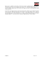
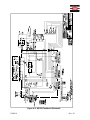
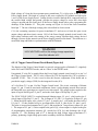
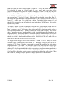
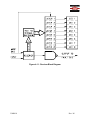
1
HUGHEY & PHILLIPS, LLC.
Installation and Operation Guide
SS-122/125
HIGH INTENSITY WHITE STROBE SYSTEM
MANUAL UM0010
Revision M
Hughey & Phillips, LLC.
136 East Court Street
Urbana, OH 43078
Telephone (937) 652-3500
Fax (937) 652-3508
www.oblighting.com
PROPRIETARY NOTICE
THIS DOCUMENT AND THE INFORMATION DISCLOSED HEREIN ARE PROPRIETARY DATA OF
HUGHEY & PHILLIPS INC. NEITHER THIS DOCUMENT NOR THE INFORMATION CONTAINED
HEREIN SHALL BE REPRODUCED, USED, OR DISCLOSED TO OTHERS WITHOUT THE WRITTEN
AUTHORIZATION OF HUGHEY & PHILLIPS INC.
NOTICE
FREEDOM OF INFORMATION ACT (5 USC 552) AND
DISCLOSURE OF CONFIDENCE INFORMATION GENERALLY
(18 USC 1905)
THIS DOCUMENT IS BEING FURNISHED IN CONFIDENCE BY HUGHEY & PHILLIPS INC.
THE INFORMATION DISCLOSED HEREIN FALLS WITHIN EXEMPTION (b) (4) OF 5 USC 552 AND THE
PROHIBITIONS OF 18 USC 1905.
Copyright 2010
All Rights Reserved
UM0010
Rev. M
REVISIONS
REV
DATE
ECO
COMMENT
A-L
To – 10/99
Varies
Reference ECO Files
M
3/25/10
Company Name Change
WARRANTY POLICY
For current warranty policy
please visit www.oblighting.com
UM0010
Rev. M
TABLE OF CONTENTS
History
Revisions…………………………………………………………………………….…2
Page
of
TABLE OF CONTENTS .................................................................................................................3 SECTION 1 - GENERAL INFORMATION ...................................................................................4 1.1 Scope .....................................................................................................................................4 1.2 General Description ..............................................................................................................5 1.3 Safety Precautions.................................................................................................................6 SECTION 2 - INSTALLATION .....................................................................................................7 2.1
2.2
2.3
2.4
Unpacking .............................................................................................................................7 Mounting and Preparation ....................................................................................................7 Installation Wiring ..............................................................................................................10 General Installation Notes ..................................................................................................14 SECTION 3 - OPERATION ..........................................................................................................14 3.1 Operating Considerations ...................................................................................................14 3.2 Controls and Indicators .......................................................................................................16 3.3 Normal Operation ...............................................................................................................19 SECTION 4 - PRINCIPLES OF OPERATION ............................................................................20 4.1 Overall Description .............................................................................................................20 4.2 Functional Description of Subsystems ...............................................................................20 SECTION 5 - TROUBLESHOOTING..........................................................................................38 5.1 All Lights Are Out ..............................................................................................................38 5.2 One Tier Of Lights Is Out. ..................................................................................................39 5.3 One Light Is Out. ................................................................................................................39 5.4 All Lights Are Flashing Out Of Synchronism. ...................................................................39 5.5 One Light Is Flashing Out Of Synchronism. ......................................................................40 5.6 One Tier Is Out Of Synchronism; All Lights Are On.........................................................40 5.7 Continuous Day, Twilight, Or Night Mode; All Lights. ....................................................40 5.8 Continuous Day, Twilight, Or Night Mode; One Light. ....................................................40 5.9 Single Low Intensity Flash In Night Operation Of One Light. ..........................................40 5.10 Frequent Fuse Blowing In The Owl. ................................................................................41 5.11 Frequent Fuse Blowing In The Controller. .......................................................................41 SECTION 6 - MAINTENANCE ...................................................................................................41 6.1 SS125 Obstruction Warning Light (OWL) ........................................................................41 6.2 SS122 Controller...........................................................................................................42 6.3 SS124 Ambient Light Sensor........................................................................................42 SECTION 7 - SPARE PARTS LIST .............................................................................................43 UM0010
Rev. M
SECTION 1 - GENERAL INFORMATION
1.1 Scope
This manual provides information about the installation, operation, and maintenance of the Type
LS-158 High Intensity Obstruction Lighting System, StrobeGuard*, an FAA Type A system for
use on structures such as chimneys and towers, developed and manufactured by Hughey &
Phillips, LLC, 136 East Court Street, Urbana, OH 43078, tel. (937) 652-3500, FAX (937) 6523508.
*Registered Hughey & Phillips Trademark
UM0010
Rev. M
1.2 General Description
The Type LS-158 Lighting System is a capacitor discharge, xenon flash strobe light system of
Flashhead/Power Supply units manufactured to comply with Federal Aviation Administration
Advisory Circular 150/5345-43 and hereinafter referred to as Obstruction Warning Lights
(OWLs). The Controller and the Ambient Light Sensor supply the various control functions for
all the lights on a single installation.
Table 1-1 lists the equipment supplied with the Type LS-158 System, noting those that are
optional. The installer and/or user should refer to their specific order to determine those options
that apply to the installation. Any optional items, when ordered, are assembled into the basic
unit at the factory.
Table 1-1. EQUIPMENT SUPPLIED
Flashhead/Power Supply Subsystem (OWL)
Enclosure, 304 Stainless Steel
Elevation Mounts
Louvers*
Interconnection Cable (77-4231), 15 ft.
Other lengths Optional
50Hz Operation*
SS125
Controller Subsystem
Enclosure, 304 Stainless Steel
Transformer, Isolation, and Step-down for
other than 120VAC, 60Hz operation
Audio Fault Alarm*
SS122
Ambient Light Sensor (3-level)
Enclosure, Molded Fiberglass
SS124
*optional
The flashhead portion of the SS125 OWL consists of a flashtube, a reflector and a high voltage
trigger transformer. The same enclosure also contains the power supply control circuits (relays,
fuses, switches, etc.), a high voltage circuit (power transformer, rectifiers, energy storage
capacitors, discharge relays and resistors), a monitoring transmitter circuit and a trigger
generator. The SS122 Controller contains control AC power for mode relays, flash interval and
timing circuits, intensity selection controls, and monitoring receivers with status indicators. The
SS124 Ambient Light Sensor contains two photocells and a switching circuit.
UM0010
Rev. M
1.3 Safety Precautions
The following general safety precautions must be observed during all phases of operation,
service, and repair of this equipment. Failure to comply with these precautions or with specific
warnings elsewhere in this manual violates safety standards of design, manufacture, and intended
use of this equipment. Hughey & Phillips assumes no liability for the customer's failure to
comply with these requirements.
1.
Any interruption of the protective (grounding) conductor (inside or
outside the instrument) or disconnecting the protective earth terminal is
likely to make this equipment dangerous. Intentional interruption is
prohibited.
2.
Whenever it is likely that the protection has been impaired, the equipment
must be made inoperative and be secured against any unintended
operation.
3.
Ensure that only fuses with the required rated current and of the specified
type (normal blow, time delay, etc.) are used for replacement. The use of
repaired fuses and the short-circuiting of fuseholders must be avoided.
4.
Adjustments described in the manual are performed with power supplied
to the equipment while protective covers are removed. Energy available
at many points may, if contacted, result in personal injury.
5.
Any adjustment, maintenance, and repair of the opened equipment under
voltage should be avoided as much as possible, and when inevitable,
should be carried out only by a skilled person who is aware of the hazard
involved. Do not attempt internal service or adjustment unless another
person, capable of rendering first aid and resuscitation, is present. Do not
replace components with power cable connected.
6.
Do not install substitute parts or perform any unauthorized modification to
the equipment.
7.
Capacitors inside the equipment may still be charged even if the
instrument has been disconnected from its source of supply.
WARNING!
The WARNING sign denotes a hazard. It calls attention to a procedure or
practice which, if not correctly performed or adhered to, could result in injury or
loss of life. Do not proceed beyond a WARNING sign until the indicated
conditions are fully understood and met.
UM0010
Rev. M
CAUTION!
The CAUTION sign denotes a hazard. It calls attention to an operating
procedure or practice which, if not correctly performed or adhered to, could result
in damage to or destruction of part or all of the equipment. Do not proceed
beyond a CAUTION sign until the indicated conditions are fully understood and
met.
SECTION 2 - INSTALLATION
2.1 Unpacking
Carefully unpack and examine each item for any obvious shipping damage. Report any claims
to the carrier immediately. Pertinent data such as installation drawings and instruction manuals
can be found in the Controller carton.
2.2 Mounting and Preparation
Any SS125 Obstruction Warning Light (OWL) may be mounted at any location on the structure,
however, the installer and/or user may determine the light number to be placed at a particular
location and install the correctly marked OWL in that position. If the installer and/or user
wishes to change the assigned number of any OWL, only the Light Number Switch SW1 (on the
Fault Transmitter Board) needs to be set differently. SW1 must be set to a different number for
each OWL (up to 32).
The SS122 Controller has one to four Fault Receiver Boards. One Receiver will monitor up to 8
differently coded Transmitters. Each Fault Receiver Board has a Receiver Block installed that
determines which set of eight OWLs it monitors. Fault Receiver Boards are installed at the
factory in their proper locations in the Controller and must remain in sequential order to operate
correctly. A -2 Receiver may not be used without a -1 being installed, a -3 Receiver must have a
-1 and a -2 preceding it, etc.
Table 2-1 Light Number Assignment
SS125 OWL No.
Transmitter No.
Receiver No.
1
1
SS125 OWL No.
Transmitter No.
Receiver No.
17 18 19 20 21 22 23 24 25 26 27 28 29 30 31 32
17 18 19 20 21 22 23 24 25 26 27 28 29 30 31 32
3
4
UM0010
2
2
3
3
4
4
5
5
1
6
6
7
7
8
8
9 10 11 12 13 14 15 16
9 10 11 12 13 14 15 16
2
Rev. M
Figure 2-1a: SS125 Outline and Mounting Dimensions
UM0010
Rev. M
Figure 2-1b: SS122 and SS124 Outline and Mounting Dimensions
UM0010
Rev. M
The elevation adjustment mounts on OWLs are factory set at 0°. These need not be changed
unless the structure upon which the OWLs are mounted is not perpendicular to the ground or the
local authorities have indicated that an adjustment is required. The elevation angle to which an
OWL should be adjusted at the time of installation should be determined by the local Federal
Aviation Administration authorities. After securing the OWL to its mount, make it level by
loosening the two hexhead cap screws on either side and adjusting its position while observing
the spirit level on the top. When the bubble on the spirit level is centered, notice the position
bracket on the lower right-hand side of the OWL. Whichever graduation mark on the bracket
lines up becomes the 0° mark. From there the OWL angle can be adjusted in either direction, the
marks being 1° apart.
The SS124 Ambient Light Sensor should be mounted within 100 feet of the SS122 Controller,
away from artificial light (eg., floodlights), and in a location that will enable it to have an
unobstructed view of the polar sky (eg., pointed north in the northern hemisphere). Local
shadowing by buildings or natural objects will cause premature intensity switching of the system
in the automatic mode and will seriously reduce the effectiveness of the system during the
critical twilight periods when visual acuity is most difficult. The Photocells are factory preset to
switch at the ambient light levels specified by the FAA. Do not alter the adjustments.
Each enclosure has a vent hole on the bottom surface which is covered with a solid plug.
Screened plugs are furnished separately to be used at the discretion of the user.
Before applying power to the equipment, check all relays and printed circuit boards to ensure
that they are all seated properly in their sockets. Check to ensure that user-installed wiring does
not interfere with relay operation when the covers are closed.
2.3 Installation Wiring
Wiring for the system should be accomplished in accordance with Figures 2-2 and 2-3.
UM0010
Rev. M
Figure 2-2: Typical Lighting System Installation Wiring
UM0010
Rev. M
2.3.1 Ambient Light Sensor to Controller (Figure 2-3a)
The Light Sensor must be mounted with an unobstructed view of the polar sky (eg., pointed
north in the northern hemisphere). The maximum distance between the Light Sensor and the
Controller is 100 feet. The minimum wire size connecting the Light Sensor and the Controller is
#14 AWG. The voltage is 120VAC.
2.3.2 Primary Power to Controller (Figure 2-3b)
The maximum power consumption is 32VA per light. The wire used should be of sufficient
gauge to ensure that the voltage drop from the source to the Controller is not greater than 3% of
the source voltage.
UM0010
Rev. M
2.3.3 Primary Power to Obstruction Warning Light (Figure 2-3c)
The maximum power consumption is 500VA per unit. This wiring may be paralleled with all
other OWLs in a system. The source of this power may, at the user's discretion, be the same as
that of the Controller. The wire used should be of sufficient gauge to ensure that the voltage
drop from the source to the furthermost OWL is not greater than 3% of the source voltage.
2.3.4 Controller to Obstruction Warning Light (Figure 2-3d)
The maximum power on control power lines (AC HI/LO) is 15VA per OWL. The maximum
power on intensity control lines (TWI/NIGHT) is 7VA per OWL. For timing and monitor lines,
use shielded twisted cable (3 conductor Belden type 8770 or equivalent) with no breaks or
junctions (#18 AWG minimum wire size recommended). Hughey & Phillips cable, P/N 774231, may be used in place of individual wires.
UM0010
Rev. M
2.4 General Installation Notes
1.
Splicing of wires other than at light levels is not recommended.
2.
Splicing of wires should be with twist-lock wire connectors or split bolt lugs. Use of
terminal strips is not recommended.
3.
All vertical wires and cable should be supported every 100 feet maximum by wrapping
wires around support bracket pins in pull boxes and/or by Kellem's grips.
4.
All power, control and ground wires should be spliced to individual cables in junction
boxes at each light level (see Figure 2-2). For splicing smaller wires, use Scotchlok twist
connectors (or equiv.) and wrap tightly with at least 6 layers of Scotch 33+ tape (or
equiv.) for moisture protection. Larger wires require Servit type connectors wrapped
with Scotchfil Electrical Putty.
5.
All factory-assembled pipe couplings should be removed and all threaded connections
coated with pipe compound prior to assembly and then tightened securely with the proper
tool.
6.
All junction/pull boxes should be installed so they can be serviced (not obstructed by
tower diagonals, girts, or transmission cables).
SECTION 3 - OPERATION
3.1 Operating Considerations
The standard main power input to the SS122 Controller is 120VAC supplied to an internal
isolation transformer. An isolation/step-down transformer must be installed for use with 208,
240, or 480VAC. The taps for the transformer are typically set at the factory for the user’s
specified input voltage.
The SS125 Obstruction Warning Light (OWL), with appropriate voltage selector block and fuse,
may be operated from 100, 120, 208, 240, or 480VAC. The source of power may be the same as
that supplied to the Controller.
CAUTION!
Controller: The output of the controller’s isolation transformer must be 120VAC.
Refer to the isolation transformer T2 nameplate for the connections of the input,
output, and tap locations used to produce 120VAC output.
Flashhead: The input voltage to the OWL flashhead must be correct. Refer to
the label on the voltage selector block on T1 to determine the voltage
configuration. Fuse F1 must match selected voltage.
UM0010
Rev. M
Figure 3-1: Component Locations - SS125 Obstruction Warning Light
UM0010
Rev. M
3.2 Controls and Indicators
This section contains descriptive information and figures to locate and identify the operating
controls and indicators of the LS-158 High Intensity Obstruction Lighting System.
3.2.1 SS125 Obstruction Warning Light (Figure 3-1)
REF. COMPONENT
A1
Power Supply Board: Printed circuit board which provides all of the DC voltages
necessary for operation of the OWL.
A2
Trigger Control Board: Printed circuit board which supplies both burst and single trigger
pulses to trigger transformer T1 in the OWL for flashtube V1.
A3
Fault Transmitter Board: Printed circuit board which monitors the flashing of flashtube
V1. If consecutive flashes are missed within a 3-second time period, transmits a signal to
the Receiver in the Controller.
DS1
Control Power Light: Pilot light that illuminates when control power is applied, and
indicates that the interlock switches are engaged.
S1
Interlock Switch: When the OWL door is opened, S1 interrupts the control power to
relay K1 on the Mother Board, causing the high voltage to be shut off and the energy
storage capacitors to discharge.
S2
Interlock Switch: Transfers intensity select lines from remote operation (by SS122
Controller) to local control by switch S3 when the OWL door is opened.
S3
Test Switch: Allows local intensity selection for the individual OWL of interest, while
not affecting the operation of any other light in the system.
UM0010
Rev. M
Figure 3-2: Component Locations - SS122 Controller
UM0010
Rev. M
3.2.2 SS122 Controller (Figure 3-2)
REF. COMPONENT
Digital Monitor Lamps: Visible through the inside cover of the Controller; one for each
light in the system. Illuminate only when a light experiences failure.
DS1
Indicator: Illuminates only when the Controller is in the DAY mode.
DS2
Indicator: Illuminates only when the Controller is in the TWILIGHT mode.
DS3
Indicator: Illuminates only when the Controller is in the NIGHT mode.
DS4
Audio Alarm: Used only when optional Audio Fault Alarm is used (not shown).
DS5
Indicator: LED that flashes with each sync pulse transmitted.
F1
Main Power Line Fuse: Value varies with input line voltage, and is marked on the inside
of the Controller cover.
S1
On/Off Power Switch: Toggle switch that interrupts input power.
S2
Mode Switch (Remote/Local): Two-pole, two-position toggle switch that permits manual
(Local) selection of the intensity levels with switch S3 or automatic (Remote) operation
through the SS124 Ambient Light Sensor.
S3
allows
Local Intensity Select Switch: Two-pole, three-position rotary switch that
manual selection of three light intensities of the system (DAY/high,
TWILIGHT/intermediate, and NIGHT/low) when switch S2 is in the Local position.
S4
Sync Inhibit Switch: Momentary pushbutton grounds pin 8 of the Sync Timing and
Driver Board, thus inhibiting the sync pulse from going to each light.
S5
Reset Switch: Momentary pushbutton resets the Digital Monitor Lamps and Relay K3
when a fault has been repaired.
TB1
Main Terminal Block: For power input and control functions to the system.
TB2
Photocell Terminal Block: For Ambient Light Sensor connections.
TB3
Alarm Terminal Block: For remote alarming.
TB4
T1 Terminal Block: For internal logic transformer.
UM0010
Rev. M
3.2.2.1 Additional Controllers
If the number of lights in a single installation exceeds 32, or if the spacing of the lights is such
that it is impractical to run wiring from a single point, more than one Controller may be used.
3.2.3 SS124 Ambient Light Sensor
This sensor monitors outside ambient light. When the Controller is operated with Mode Switch
S2 in the Remote position (normal operating position), this Sensor controls the automatic
changing of the three light intensities.
3.3 Normal Operation
After the system has been correctly wired according to the electrical installation instructions
(Section 2), ensure that the Controller power is OFF. Ensure that the covers of the Obstruction
Warning Lights (OWLs) are closed, and that the OWL light beams are aimed properly. Select
the LOCAL operating Mode of Controller Switch S2. Set Switch S3 to the DAY position.
Switch on Primary Power to OWLs. Random flashing should begin.
Switch Controller Power Switch S1 to the ON position. After a delay of approximately 3
seconds, all lights should flash at the prescribed rate and sequence. The system flash rate is
preset for 40 flashes per minute, and all lights flash simultaneously. The DAY status light
should be on.
After checking the LOCAL operation of the system in the DAY mode, Local Intensity Switch S3
should be set to the TWILIGHT position. After a short delay, the system should be flashing at
the prescribed rate and the TWILIGHT status light should be on. Then, switch Local Intensity
Switch S3 to the NIGHT position. After a short delay, the system should flash at the prescribed
rate, and the NIGHT status light should be on.
The Light-Emitting Diodes (LEDs) mounted on the Receiver Board(s) A2-A5 are visible through
holes provided and should remain extinguished until a fault is detected. If any LED illuminates,
momentarily depress Reset Switch S5.
After operating the system as above, switch Remote/Local Mode Switch S2 to the REMOTE
position. After a short delay, the system should flash at the prescribed rate. In the REMOTE
position, the operational intensity level of the system is controlled by the Ambient Light Sensor
(Photocell). The Photocell senses the ambient light level and automatically switches the system
among the DAY/TWILIGHT/NIGHT intensities.
The Photocell has a built-in delay to prevent random occurrences, such as clouds or birds
blocking sunlight, from causing unwarranted switching of the system intensity.
UM0010
Rev. M
SECTION 4 - PRINCIPLES OF OPERATION
4.1 Overall Description
The Type LS-158 High Intensity Obstruction Lighting System meets the requirements of the
FAA Type A system. All the lights at a given installation flash synchronously.
Main power to the SS125 Obstruction Warning Light (OWL) is converted to a high DC voltage
to bias the flashtube.
The SS124 Ambient Light Sensor (Photocell) sends correct control power signals via the SS122
Controller to automatically change the light intensity of the OWL.
Main power input to the Controller is applied to the control and logic circuits. Control power to
the OWL activates relays which determine the intensity of the flash. Logic circuits in the
Controller generate a sync timing signal which controls the rate of flash. On receipt of the sync
timing signal from the Controller, the OWL will transmit a trigger pulse, firing the flashtube. If
the flashtube does not fire, the OWL will transmit a monitor signal back to the Controller,
indicating a fault with that particular unit.
Figure 4-1. System Block Diagram
4.2 Functional Description of Subsystems
4.2.1 SS125 Obstruction Warning Light
Main AC input power to the lights is transformed to high voltage DC and stored in capacitors.
The flashtube, which is in parallel with the capacitors, is fired by the trigger circuit, discharging
the capacitors, producing a flash of light. The intensity of the light is varied by changing the
energy stored between flashes (by changing the capacitance). The flashtube extinguishes when
current from the capacitors is too low to support the arc. The short circuit current is set below
the minimum tube current to prevent continuous conduction. The capacitors then recharge for
the next flash.
UM0010
Rev. M
Input power is applied to the primary of the ferro-resonant, regulating power transformer T1
when main power relay K1 is energized (see Figure 4-2). The high voltage output of T1 is
rectified by high voltage module CR5 on the Power Supply PC Board A1 and charges the energy
storage capacitors.
In the DAY mode (high intensity) normal operation has K1 and K2 energized while K3 and K4
are de-energized. This keeps capacitors C1, C2, and C3 in the high voltage circuit. With this
amount of capacitance in the circuit and the DC voltage provided, sufficient energy is discharged
through flashtube V1 to yield an effective intensity of approximately 270,000 candelas.
UM0010
Rev. M
Figure 4-2: SS125 Flashhead Schematic
UM0010
Rev. M
In the TWILIGHT mode (intermediate intensity), 110VAC is applied to the OWL on TB1-5.
This signal comes from the Controller and energizes relay K4. When K4 energizes, its contacts
remove capacitor C3 from the high energy circuit and prevent it from being charged. Capacitors
C1 and C2 are still in the high energy circuit and their energy, discharged through flashtube V1,
will yield an effective intensity of approximately 20,000 candelas.
In the NIGHT mode (low intensity), 110VAC is supplied from the Controller and applied to the
OWL on TB1-4 and the coil of K3, thus energizing K3. Note that K4 remains energized. When
K3 is energized, its contacts will remove C2 from the high energy circuit and prevent it from
being charged. Now only C1, with R1 in series, is in the tube circuit; this provides the required
energy to produce the effective intensity of approximately 2,000 (or 4,000) candelas.
Concurrently, 110VAC will be applied to pin 4 of the Trigger Control PC Board.
4.2.1.1 Power Supply Printed Circuit Board
The Power Supply board (Figure 4-3) provides all the DC voltages necessary to operate the
SS125 Obstruction Warning Light. 120VAC is applied to pins 14 and 16 of the Power Supply
board. This AC voltage is fed to the primary of transformer T1. T1 has dual low voltage
secondary windings connected in parallel. The output is full-wave rectified by CR1, CR2, CR3,
and CR4, and filtered by C1. This circuit produces an unregulated ≈25VDC which is fed to pins
21 and 22 of the Power Supply board through resistors R1 and R2, respectively, and on to pin 3
of the Trigger Control board plus pin 22 of the Fault Transmitter board. Pin 22 of the Power
Supply board goes to pin 10 of the Fault Transmitter board.
Figure 4-3: Schematic - Power Supply Board (A1)
UM0010
Rev. M
High voltage AC from the ferro-resonant power transformer T1 is fed to pins 8 and 11 of the
Power Supply board. This high AC voltage is full-wave rectified by CR5 module and fed to pins
1 and 2 of the Power Supply board. Voltage divider circuit R4 through R10, connected between
the rectified high voltage and ground, provides the proper voltage to excite DS1 when high
voltage is present and also feeds pin 4 of the Power Supply board with a pulse representing the
discharge of the flashtube V1. This pulse coming out of pin 4 is fed to the Fault Transmitter
board pin 7. The use of the high voltage pulse is described in a later section.
C4 is the resonating capacitor for power transformer T1 and serves to limit the open circuit
output voltage and short-circuit current. DS1 of the Power Supply printed circuit board is the
high voltage indicator and is the analog of the energy storage capacitor high voltage derived
through a resistor divider network on the Power Supply printed circuit board. This indicator is a
neon-filled lamp and blinks in synchronization with the flashtube.
WARNING!
HIGH VOLTAGE is still on the energy storage capacitors
when this indicator is lit!
4.2.1.2 Trigger Control Printed Circuit Board (Figure 4-4)
The function of the Trigger Control board is to provide a trigger pulse to flashtube V1, singularly
in the DAY and TWILIGHT modes, and in a "burst" in the NIGHT mode.
Unregulated 25 volts DC is supplied from the Power Supply printed circuit board A1 to pin 3 of
the Trigger Control board. The 25 volts is filtered by C10 and regulated by CR7 to produce a
regulated 15VDC. This 15 volts is used to bias the discrete components of the board and to
provide the supply voltage (VDD) for the integrated circuits (ICs).
AC is fed from T1-3 to pin 14 of the Trigger Control board. The circuit, consisting of Schmitt
trigger U1, pin 13 and its associated components, forms a pulse-shaping network that converts
the sinusoidal wave train input to a square wave train output. This output is then coupled to the
input of logical NAND gate U2, pin 12, and to the clock input of D flip-flop U3, pin 3.
The SYNC PULSE INPUT is coupled through Schmitt trigger U1, pin 1, which pulses the C
(clock) input of flip-flop U3, pin 11. The Q output of U3, pin 13, is coupled to D input U3, pin
5. When the 60Hz square wave clocks U3, pin 3, Q output, pin 1, will enable the other half of
U2, pin 13. U2 thus enabled will give an output pulse on pin 11, then fed to U2, pins 1 and 2.
The pulse is inverted and outputted on U2, pin 3, and presented to 7-stage binary counter U4, pin
1. The output of U2, pin 3, is also coupled to the gate of Q1, whose output is coupled to the gate
of programmable unijunction transistor Q3, which fires SCR, Q4, and discharges the 0.5µF
capacitor, C7. The discharge path of C7 is through the high voltage trigger transformer T2
primary, producing a high voltage pulse on the secondary which fires flashtube V1.
UM0010
Rev. M
In the DAY and TWILIGHT modes, U5, pin 8, is held at a "1" level, and enabled such that when
U4 is clocked, Q1 output, pin 12, will enable U5, pins 1 and 2, and a reset pulse will be
generated which will reset U3 and U4 and thus disable gate U2, pin 13, so that only one pulse
will be coupled to Q4 gate. This is the single-shot mode, which repeats every 1500ms.
In the NIGHT mode, 120VAC is fed to pin 4 of the Trigger Control board, turning on Q6. This
puts a ground or a "0" level on U5, pin 8. With this gate thus disabled, a reset pulse from U5,
pin 10, will not appear until there is an output from the Q3, pin 9, section of U4. This occurs at a
count of 7, at a 60Hz rate. This yields a time >100ms. During this 100ms duration, Q3, and
thereby CR4, are turned on and off and fire the tube in the "burst" NIGHT mode. This cycle is
repeated every 1500ms.
The output of inverter U2, pin 3, in addition to firing the SCR, is also coupled through R2 to the
plus (+) side of C1 and the gate of Q1. If for any reason (an IC failure) the board continues to
burst, or run away, then C1 will integrate these pulses and will be charged up until it reaches a
level high enough to turn on Q1. When Q1 is turned on, it will disable U1, pin 5. The above is
done to prevent a run-away condition, which could potentially damage the flashtube or the
trigger transformer. When and if the above occurs, the light will flash in the SELF-OSCILLATE
mode. In this mode, the light flashes approximately every 2.5 seconds, and the trigger pulse to
the tube is realized by the resettable oscillator circuit. This SELF-OSCILLATE mode will also
be in effect in the event of a loss of the SYNC PULSE.
The trigger circuit energy is derived from terminals T1-6 and T1-2 of T1 through a rectifier
circuit on Trigger Control printed circuit board A2. This trigger energy is stored in a 0.5µF
capacitor (C7 on Figure 4-4) whose charge path is through the primary of the high voltage
trigger transformer T2 to ground. The flash timing pulse (sync pulse) from the Controller goes
in the Trigger Control board on pin 18 and fires a Silicon Controlled Rectifier (SCR). This
discharges the 0.5µF capacitor through the high voltage trigger transformer primary, producing a
high voltage pulse on the secondary which fires flashtube V1. The recharge current for the
0.5µF capacitor is limited by a series resistor to a value below the hold in current of the SCR so
that it turns off, allowing the 0.5µF capacitor to charge again in time for the next flash.
UM0010
Rev. M
Figure 4-4: Trigger Control Board Schematic
UM0010
Rev. M
4.2.1.3 Fault Transmitter Printed Circuit Board (Figure 4-6)
The digital monitoring system that is employed in the Type LS-158 High Intensity Obstruction
Lighting System, StrobeGuard, consists of a Transmitter, located in each Obstruction Warning
Light (OWL), and a Receiver located in the Controller. With the present configuration, the
system has the capability of monitoring and identifying 1 to 32 lights. One Transmitter is
required at each light. For 1 through 8 lights, one Receiver is required in the Controller. For 9
through 16 lights, two Receivers are required in the Controller. For 17 through 24 lights, three
Receivers are required, and for 25 through 32 lights, four Receivers are required.
The Fault Transmitter is a printed circuit board which utilizes integrated circuits in conjunction
with discrete components to form a self-contained module. The simplicity of its function is
shown on the block diagram (Figure 4-5). The board and its connector are keyed to ensure
proper orientation and location.
Figure 4-5: Fault Transmitter Block Diagram
The multivibrator MV consists of one-half of U4 with its components C9, C10, R10, and R11.
The output of the MV is a 0 to +12V square wave having a period of <1 second. This output is
continuously fed into the ÷4 binary counter. The ÷4 binary counter, consisting of U5 and onequarter of U4, is reset with every synchronous flash of the light, thus ignoring the MV input as
long as the light is functioning.
Resetting U5 is accomplished by using the output of U4, pin 4, which is the output of the
coincidence circuit. This signal is AC coupled through C7 to reset pins 4 and 10 of U5.
The Timing Input Driver (TID), consisting of 2 gates U1 and half of U2, receives the
synchronizing pulse on pin 4 of the board. This pulse, conditioned by U1, a Schmitt trigger, is
presented to one of the clock inputs (pin 3) of U2 and to the inputs, pins 1 and 2 of U3. The Q
output of U2, pin 1, is presented to one input of U3 (pin 12).
The Analog Input Driver (AID) consists of one gate of U1 and the other half of U2. Each time
the light flashes, the high voltage discharges then recharges, thus going up and down. An analog
UM0010
Rev. M
of this fluctuation is presented to the transmitter board on pin 7. This high voltage pulse is
conditioned by Schmitt trigger U1 and presented to a clock input (pin 11) of U2. The Q output
(pin 13) of U2 is sent to one of the inputs of U3 (pin 13). With both inputs (pins 12 and 13) of
U3 thus conditioned, the output (pin 11) will condition one input (pin 6) of U4. The other input
(pin 5) of U4 is conditioned by the output of U3, pin 4, which was conditioned by the
synchronizing pulse from the TID. Coincidence of the synchronizing pulse and the high voltage
pulse allows an output from U4, pin 4. This output is AC coupled through C7 and resets the ÷4
counter, pins 4 and 10, of U5. Therefore, as long as the light is flashing, at the correct rate, the
÷4 counter continuously resets and will not enable the transmitter.
If the light does not flash, or if the SYNC pulse is missing, or if the light is in the "self-oscillate"
mode and is flashing at the wrong rate, coincidence will not occur and the counter will not reset.
At the end of four cycles of the Multivibrator, the two Q outputs of counter U5 will condition the
inputs of gate U4, pins 8 and 9, which in turn will bias the Q1 gate, thus turning Q1 on. When
Q1 is turned on, its drain, which was sitting at 12V, will go low and will enable Transmitter
Module at U6, pin 13.
The Transmitter Module (which plugs into U6 and XA1) transmits any one of 32 different Group
Codes. Each Group Code consists of of three sequential tones. There are four frequency ranges,
and 8 tone sequences in each range. The Group Code to be transmitted is set by SW1 on the
Transmitter Module. Locate SW1 on the Fault Transmitter Board using Figure 4-7a. Figure 47b lists the proper switch settings for each light number.
Each Group Code transmission is preceded by a delay interval of 1.5 seconds. The Group Code
transmissions continue until control power is shut off to that unit, or until the light starts flashing
again, thus resetting the MV.
The output of the Transmitter is fed to the line driver, which consists of Q4, whose function is to
drive the signal down the line to the Receiver. The line driver is diode-isolated to prevent
erroneous feedback.
UM0010
Rev. M
Figure 4-6: Fault Transmitter Board Schematic
UM0010
Rev. M
Figure 4-7a: SW1 Location (Light Number 6 Switch Settings Shown)
UM0010
Rev. M
Light
Number
1
2
3
4
5
6
7
8
9
10
11
12
13
14
15
16
SW1 DIP Switch Position
1
2
3
4
5
On
On
On On
On
On
On
On On
On On On
On
On
On
On
On
On On
On
On On
On
On On
On On On
On On On On
-
Light
Number
17
18
19
20
21
22
23
24
25
26
27
28
29
30
31
32
SW1 DIP Switch Position
1
2
3
4
5
On
On
On
On
On
On On
On
On
On
On
On
On
On On
On
On On On
On
On On
On
On On
On
On On
On On
On On
On On On
On
On On On
On On On On
On On On On On
Figure 4-7b: Switch Settings for Light Number (“-” is Off)
4.2.2 SS122 Controller (Figure 4-8)
The Controller supplies control AC Power, provides the flash timing pulse (SYNC PULSE),
automatically selects the proper intensity level, monitors all the outputs of the Digital Monitor
Transmitters, and automatically identifies which light, if any, is malfunctioning, and displays the
number of that unit.
A Primary Power Switch, separate from the Controller, is used to disable the Obstruction
Warning Lights (Paragraph 2.3.3).
AC HI is applied to TB2-3 out to the SS124 Ambient Light Sensor, which controls automatic
remote operation. AC HI is also applied to E13 and further LOCAL INTENSITY select switch
S3, and to terminal E18 to logic transformer T1, which powers the control logic circuits.
Intensity control is accomplished with 120VAC circuits through S2 (MODE) and S3 (LOCAL
INTENSITY) switches, or through the Ambient Light Sensor (Photocell).
When the MODE switch (S2) is in the REMOTE position, K4 and K5 are controlled by SS124
Ambient Light Sensor in lieu of S3. Operation of the Sensor is as follows:
In daylight, both switch circuits 1 and 2 of the Sensor remain open; therefore, K4 and K5 are not
energized, and control AC is not applied to TB1-4 or 5.
When the ambient light level decreases from day to night, circuit 1 of the Ambient Light Sensor
closes when the light level is between 60 and 35 foot-candles, energizing K4. This is the
UM0010
Rev. M
TWILIGHT (intermediate intensity) operation of the system, and control AC is applied to TB15.
When the ambient light continues to decrease and reaches a level of between 5 and 2 footcandles, circuit 1 remains closed and circuit 2 of the Ambient Light Sensor closes, energizing
K5. This is the NIGHT (low intensity) operation of the system and control AC is applied to
TB1-4 and 5.
When the ambient light level increases from NIGHT to DAY, operation of the Ambient Light
Sensor is just the opposite of the above. Increasing from 2 to 5 foot-candles, circuit 2 opens up,
de-energizing K5. Rising from 35 to 60 foot-candles, circuit 1 opens up, de-energizing K4. The
system changes intensity levels accordingly.
The DC Power Supply provides 28 VDC for relays, 24 VDC for line driver power, and shunt
regulated 12 VDC for logic control. All components, except logic power transformer T1 and 28
VDC filter capacitor C3, are located on Sync Timing and Driver printed circuit board A1 (Figure
4-9). Synchronous flash timing pulses are generated on this same board and amplified to a
positive 24-volt pulse capable of timing up to 32 lights. The pulse duration is approximately 2
milliseconds.
UM0010
Rev. M
Figure 4-8: SS122 Controller Schematic
UM0010
Rev. M
Figure 4-9: Sync Timing & Driver Board Schematic
UM0010
Rev. M
4.2.3 Digital Monitor Receiver
The Digital Monitoring Receiver is a printed circuit board which utilizes integrated circuits in
conjunction with discrete components to form a self-contained module (Refer to Figures 4-10
and 4-11).
The Multicode Receiver, consisting of U1 and associated components, is programmed to decode
any one of eight different input Group Codes all based on sequential permutations of the three
programmed frequencies. The three code frequencies are determined by resistors RA, RB, and
RC connected to pins 8, 7, and 6, respectively. The values of RA, RB, and RC, given in the
tabulation on the schematic, determine the frequencies the Receiver listens to. Receipt of a
programmed code appears at the X, Y, and Z logic outputs as a three line binary code.
Following receipt of a code, the appropriate data are maintained at the X, Y, and Z outputs until
a different code is received or until reset by the Master Reset Bus. No change takes place at the
X, Y, and Z terminals if the displayed code is repeated. For every programmed Group Code
received, including repetitive codes and irrespective of the status of the control inputs (pins 13
and 14), a pulse appears at the code received output, pin 15. This pulse is maintained for
approximately two cycles of the third code tone, the trailing edge occurring simultaneously with
any updating of the X, Y, and Z outputs. The new data is latched into U2(BCD to decimal code)
viaU6. The data in U2 is periodically cleared by the fault hold timer. When the FAULT BUS is
driven negative, it turns on an SCR on Sync Timing and Driver printed circuit board A1, which
produces a ground on one side of fault relay K3. This SCR circuit latches in the ON position
until RESET pushbutton S5 is depressed. This pushbutton removes 28 VDC from K3, allowing
the SCR to reset and applies a reset signal to the MRST RESET BUS which resets the Receiver
and latches. If the fault has not been corrected, the operation will repeat itself.
The control mode inputs of the Receiver (pins 13 and 14) are programmed to an "update
continuously" mode of operation. In this mode the X, Y, and Z outputs reflect the last Group
Code received; thus, if more than one Group Code (more than one light) is received, all codes
will be recognized and sent to the BCD to decimal decoder U2. The outputs of U2 are fed to one
of eight circuits which will turn on the light emitting diode (LED) corresponding to the faulty
light. The LED will remain lit until the latches are reset by the MRST BUS. If the fault has not
been corrected, this operation will also repeat and relight the LED.
Automatic reset timer U5 resets latches after approximately one minute, regardless of pushbutton
reset S5.
UM0010
Rev. M
Figure 4-10: Digital Monitor Receiver Schematic
UM0010
Rev. M
Figure 4-11: Receiver Block Diagram
UM0010
Rev. M
SECTION 5 - TROUBLESHOOTING
WARNING!
1.
2.
3.
4.
5.
6.
7.
Always turn power OFF when changing any component or printed
circuit board.
HIGH VOLTAGE is present in the Obstruction Warning Light
(OWL). Do not cheat the interlocks.
Do not put hands or tools in the OWL until the neon lamp on the
Power Supply board (A1) is extinguished.
Do not look directly into the flashhead at close range when it may
flash.
Replace components in the order stated, keeping track of those
replaced.
The following procedures presume that all fuses, interlocks, and
controls are functioning properly.
The components and assemblies in this system were designed by
H&P to handle the high voltages which are present. We do not
recommend substituting components or assemblies which might be
available through other vendors.
5.1 All Lights Are Out
CAUSE - Probably within the power control circuits in the SS122 Controller.
1.
Check fuses and switch positions (measure Main Power, TB1-3 to TB1-2).
2.
Verify that E26 is not shorted to ground.
3.
Verify output voltage of 120VAC on E26 with respect to E25. If no voltage,
check T2.
4.
Verify control voltage 120VAC on TB1-6 with respect to TB1-7. If present,
Controller is operating properly and fault is elsewhere.
5.
Replace, in order, K1, K2, K4, K5, K6, and K7 of the Controller, checking for
successful operation with each one.
6.
Check for +28VDC on E2 (+) to chassis, then for +24VDC on E20 to chassis.
7.
Replace Sync Timing and Driver printed circuit board A1.
UM0010
Rev. M
5.2 One Tier Of Lights Is Out.
CAUSE - Probably a loss of input power to that tier and not a system failure.
WARNING!
When operating any Obstruction Warning Light (OWL) locally, the following
procedure must be followed:
1.
2.
3.
4.
Open OWL door.
Pull Interlock Switch S1. Unit should now be operating.
Turn Test Switch S3 to change intensity, if desired.
When maintenance is complete, close and secure OWL door. The unit
will automatically revert to the intensity dictated by the Controller.
5.3 One Light Is Out.
CAUSE - Any of the following:
1.
Check fuses. If the fuses are not blown,
2.
Verify that the HV Indicator in the OWL is on.
3.
If HV Ind. is off, replace Power Supply board A1, and check operation of K1
relay.
4.
If HV Indicator is still off, check voltage on C4 and T1.
5.
If HV Indicator is on, replace Trigger Control printed circuit board A2.
6.
If flashtube still does not flash, verify presence of a trigger spark (faint thread-like
blue arc from end to end of flashtube V1).
7.
If trigger spark is missing, replace Trigger Control printed circuit board A2.
8.
If light still does not flash, replace flashtube V1.
9.
If light still does not flash, replace Trigger Transformer T2 assembly.
5.4 All Lights Are Flashing Out Of Synchronism.
CAUSE - SS122 Controller timing failure.
1.
UM0010
Observe flash timing pulse as a flick of the needle on a Simpson 260 Multimeter,
or equivalent, set on the 10VDC range, with (+) on TB1-11 and (-) on TB1-10.
Rev. M
2.
If Controller input power is correct, replace Sync Timing and Driver PC board
(A1).
3.
Check sync pulse distribution wiring.
5.5 One Light Is Flashing Out Of Synchronism.
CAUSE - Faulty OWL trigger circuit.
1.
Replace Trigger Control PC Board A2 in the SS125 Obstruction Warning Light.
5.6 One Tier Is Out Of Synchronism; All Lights Are On.
CAUSE - Faulty line circuit from Controller to junction box on that tier.
1.
Check sync pulse wiring distribution on that tier.
5.7 Continuous Day, Twilight, Or Night Mode; All Lights.
CAUSE - Faulty photocell or relays.
1.
Check correct intensity when manually selecting intensity levels in the Controller
per Section 4.
2.
If correct, replace the photocell in the SS 124 Ambient Light Sensor.
3.
If incorrect, replace K4, K5, K6 and K7 for proper operation.
4.
If still incorrect, check S3 for proper operation.
5.8 Continuous Day, Twilight, Or Night Mode; One Light.
CAUSE - Faulty OWL relay.
1.
To correct continuous operation in the DAY mode, replace K3 and K4.
2.
To correct continuous operation in the TWILIGHT or NIGHT modes, replace K3,
K4 and DB1.
5.9 Single Low Intensity Flash In Night Operation Of One Light.
CAUSE - Faulty Trigger Control PC Board A2.
1.
UM0010
Replace Trigger Control printed circuit board A2.
Rev. M
5.10 Frequent Fuse Blowing In The Owl.
CAUSE - Defective component in OWL.
1.
If blown fuse is F1, replace K1 and DS1. Check for arcs. Check S1, S2 and S3.
2.
If blown fuse is F2, replace Power Supply PC Board A1. Replace blown fuse and
turn on power. If fuse blows again, replace Trigger Control PC Board A2. If fuse
still blows, replace C4, K1 and T1. Check wiring harness.
5.11 Frequent Fuse Blowing In The Controller.
CAUSE - Defective components in the Controller.
1.
Replace K1, K2, K4, K5, K6 and K7.
2.
Replace Sync Timing and Driver printed circuit board A1.
3.
Replace T1.
4.
Replace optional T2, if installed.
5.
Check cable harness.
6.
Remove wires that connect to the Ambient Light Sensor and check for shorts.
SECTION 6 - MAINTENANCE
6.1 SS125 Obstruction Warning Light (OWL)
Normal maintenance of the OWL requires periodic cleaning of the window with a non abrasive
soap.
WARNING!
Ensure that the power is OFF and the capacitor bank has been discharged before
opening the OWL.
6.1.1 Flashtube Replacement
Flashtubes which are faulty or degraded in performance by aging should be replaced by the
following procedure:
1.
Shut off the power.
2.
Release the OWL cover.
3.
Swing the cover open, exercising caution not to damage the glass face or the
gasket.
UM0010
Rev. M
4.
Release the old flashtube by disconnecting the electrode wire fastons at each end
and carefully snapping the tube from its holders.
5.
Unpack the new flashtube, being careful not to touch the glass envelope.
6.
Holding the flashtube by its metal ends, center it in the reflector assembly and
snap it into place, making sure the red mark on the flashtube matches the red
mark on the socket assembly.
7.
Attach the faston connector at each end of the flashtube to each socket assembly.
8.
Dress the electrode wires up and away from the sides of the reflector.
Figure 6-1: Flashtube Replacement
9.
6.2
Close and fasten the OWL cover.
SS122 Controller
No special or preventive maintenance is required for the Controller.
6.3
SS124 Ambient Light Sensor
The only maintenance required for this unit is the periodic cleaning of the Photocells. Frequency
of cleaning will depend on the environment to which they are exposed.
UM0010
Rev. M
SECTION 7 - SPARE PARTS LIST
SS125 OBSTRUCTION WARNING LIGHT (OWL)
Capacitor, 1µF C1 ................................................................................................... 77-4220
Capacitor, 3µF C4 ................................................................................................... 77-3311
Capacitor, 12.5µF C2 .............................................................................................. 77-4108
Capacitor, 110µF C3 ............................................................................................... 77-4133
Diode Block Assembly DB1 .............................................................................. 277-3342-6
Flashtube Assembly V1 .......................................................................................... 77-3295
Fuse, 1A, 3AG, Slo-Blo F2,F3,F4,F5 ..................................................................... 77-2365
Fuse, FNQ, 3.2A (for 480VAC) F1 ........................................................................ 77-2041
Fuse, FNQ, 6A (for 240VAC) F1 ........................................................................... 77-1167
Fuse, FNQ, 10A (for 120VAC) F1 ......................................................................... 77-2040
Interlock Assembly, Power S1,S2,S3,DS1 ............................................................. 77-3323
PC Board, Mother .................................................................................................. 277-3264
PC Board, Power Supply A1 ................................................................................ 277-3261
PC Board, Trigger Control A2 .............................................................................. 277-3262
PC Board, Fault Transmitter A3 ........................................................................... 277-3263
Reflector Assembly ................................................................................................ 277-3898
Relay, Contactor K1 ............................................................................................... 77-2878
Relay, SPDT, 120VAC, HV K2,K3,K4.................................................................. 77-2013
Resistor Assembly, Power R1,R5,R6 ................................................................... 277-3546
Resistor Assembly, Power (Europe) ...................................................................... 277-4238
Transformer Assembly, Trigger T2 ...................................................................... 277-3324
Transformer, Power T1 (60Hz).............................................................................. 77-3890
Transformer, Power T1 (50Hz).............................................................................. 77-4244
SS122 CONTROLLER
PC Board, Mother .................................................................................................. 277-3047
PC Board, Sync Timing and Driver A1 ................................................................ 277-2673
PC Board, Digital Monitor..................................................................................... 277-2536
Relay, 3PDT, 24VDC K1,K2,K3,K6,K7 ................................................................ 77-3041
Relay, K4,K5 ........................................................................................................... 77-2710
Transformer Assembly, Power Logic T1.............................................................. 277-2214
Transformer, Power,T2, 240/480, 50/60Hz ............................................................. 77-2549
Transformer, Power,T2, 120/230/240, 60Hz ........................................................... 77-3886
Transformer, Power,T2, 208/220, 50/60Hz ............................................................. 77-3144
Fuse, FNQ, 10A (for 120VAC) F1 ......................................................................... 77-2040
SS124 PHOTOCELL
Photocell, Twilight................................................................................................... 77-3258
Photocell, Night ....................................................................................................... 77-3259
Receptacle, Photocell ............................................................................................... 77-3257
UM0010
Rev. M