1
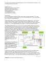
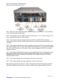
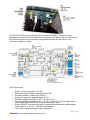
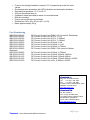
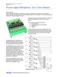
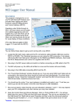
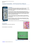
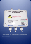
Filename: DC Current Control Unit User Manual.docx Date: 11 August 2015 Version: 1.30 DCCurrentControlUnit(DCCU)UserManual Description This product has been designed to provide the various current control and monitoring functions required for any system requiring bipolar current control between 0 and 2 A DC at up to about 20 V. The DCCU provides a controlled current output from 0 to 2 A when powered from a 24 V 2.5 A DC power supply. It requires this external power supply to supply the load as well as the internal control circuitry. Inherently this means that the load, the output monitoring, the 0-5 V control input and the process signal inputs are connected to the 0 V terminal of Vin. Therefore there is no galvanic isolation between any of these connections. However the PWM input, the OUTPUT ON/OFF and the POLARITY REVERSE inputs are optically isolated and therefore when using this with a Measurement and Control Interface (MCI) and a single 24 V 2.5 A power supply one can achieve isolation from the load, the power supply and the MCI. If the monitoring outputs are going to be used, one should use an isolating signal converter to achieve isolation. We manufacture suitable isolating converters with zero and span adjustments as well as filtering for noisy signals. The DCCU produces an output of 0 to 2 A in direct proportion to the input control signal. Three types of input control signals can be used, they are: 0 to 5 V - directly into the current control stage A Pulse Width Modulated input (0 to 5 V or 0 to 24 V) going from 0 to 100 %. (Typically one of the MCI PWM outputs). A process signal input - typically 0 to 10 V, 0 to 20 mA or 4 to 20 mA (must be configured for the desired input signal type before delivery). 1|Page danntech – PROCESS INSTRUMENTATION 2015 © The type of input desired is selected using one of three internal jumper switches - only one being selected at any time. Applications Proportional hydraulic valve control. Electrochemistry applications. Microbial growth control systems. Plating applications. Cell charging and control. Automated current control. Operation As an example when using the PWM control input (inverted operation) - 75 % duty cycle will produce an output current of 0.5 A, 50 % and output of 1 A, 25 % an output of 1.5 A and 0 % will produce 2 A. [Typical MCI values used are: PWM Output Frequency (register 38) = 100 (143 Hz) which produces a linear output current results when the PWM Output Duty Cycle (register 40 or 42) is changed. Typically 255 gives an output of 0 A, approx 140 gives an output of 1 A and approximately 10 produces 2 A (this relationship is linear)]. Two isolated digital inputs (0 to 5 V or 0 to 24 V) are provided to switch the output on and off as well as reverse the polarity of the output current. Applying a digital input to the OUTPUT ON/OFF input switches the output on. With the signal removed the output will remain off. Applying a digital input to the POLARITY REVERSE input reverses the output polarity - with this input at 0 output connection A will be positive and B the return, applying 5 or 24 V (depending upon the internal jumper selections) will reverse the output polarity so that B becomes positive and A the return. With nothing connected to this input terminal A is positive. The input impedance is 3K9 when configured for 24 V input and 560R when set up for a 5 V input. A main feature of this device is that it provides a linear current control (as opposed to a switched mode type of current control). This means that the output is electrically very quiet and the control smooth and linear. Two monitoring outputs are provided, they are NOT isolated from the input power supply or the load. The output voltage monitoring output produces 0 to 10 V in proportion to the output voltage going from 0 to 20 V. i.e. at an output voltage of 10 V this output will be at 5.00 V. For an output voltage of 15 V this output will be 7.5 V and for 20 V it will be 10.00 V. The load current monitoring output produces an output of 0 2|Page danntech – PROCESS INSTRUMENTATION 2015 © to 10 V for a load current of 0 to 2 A. (In the earlier versions a different current monitoring voltage is produced when changing from I a>b to I b>a. It is linear and repeatable in each current direction but it is different. The exact calibration information will be supplied with the product. Internally the series regulating element (a FET) is fan cooled, as it can dissipate up to 20 V at 2 A = 40 W. If the fan should fail or the power dissipation be exceeded and the temperature rises above a preset level then the unit will switch off automatically until the temperature decreases when it will switch back on again. This temperature threshold is adjusted using VR8 (beneath the right hand side cover), it is initially set to approximately 70 deg C. An output voltage monitoring circuit indicates when the output voltage goes above about 20 V – typically when the load is disconnected or the output voltage compliance is exceeded (more than about 10 ohms). An LED indicates when this occurs and VR3 sets the output voltage at which the LED illuminates (beneath the left hand side cover). ConnectionDetails PWM IN+, PWM IN- - Pulse width modulator input, 0-5 V or 0-24 V (depends on internal configuration). 0V, Sin (4-20mA) - Process signal input, typically 0-20 mA or 4-20 mA. 0V, 0-5 Vin - Direct voltage control input. +Vin, 0Vin - Power supply input, 24 VDC. The POLARITY REVERSE control input reverses the polarity of the output current, 0-5 V (J5 in) or 0-24 V (J5 out) (depends on internal configuration). When off the conventional current flow is from A to B, when switched on the conventional current flow is from B to A. The OUTPUT ON/OFF control input switches the output on, 0-5 V (J6 in) or 0-24 V (J6 out) (depends on internal configuration). Iout(0-10V) - Load current monitoring output 0 to 10 V = 0-2 A (not isolated) Vout(0-10V) - Load voltage monitoring output 0 to 10 V = 0-20 V (not isolated) OUT A, OUT B - Output connections to the load (OUT A nominally +ve) 3|Page danntech – PROCESS INSTRUMENTATION 2015 © InternalTrimpotAdjustments Beneath the left-hand side cover – VR1 - Sets the Pulse Width Modulated input scaling so than at 0 to 5 V is produced at J2 for the input pulse width range. VR2 - This sets the current output for the full scale input, i.e. at 5 V input using the 0-5 Vin one should trim this for 2.00 A output. VR3 - This trimpot sets the voltage at which the Red Vout MAX LED illuminates. Typically one would set this to just switch off with a 10 ohm load connected at 2 A (20 V output). VR4 - This trimpot calibrates the output voltage monitoring circuit. One should arrange the output voltage to be 10 V and then adjust VR4 so that 5.00 V is measured between the Vout (0-10 V) and the 0 V terminals. At an output voltage of 20.00 V you should measure 10.00 V. VR5 - This trimpot calibrates the output current monitoring circuit. One should arrange the output current to be 2.00 A and then adjust VR5 so that 10.00 V is measured between the Iout (0-10 V) and the 0 V terminals. At an output current of 1.00 A you should measure 5.00 V. VR6 - This trimpot adjusts the zero setting for the Sin control input. VR7 - This trimpot adjusts the span setting for the Sin control input. Beneath the right-hand side cover - VR8 - This trimpot sets the temperature at which the thermal shutdown will come in to effect. Initially set for approximately 70 deg C. 4|Page danntech – PROCESS INSTRUMENTATION 2015 © The DCCU is DIN rail mounting with plug-in screw terminals. The enclosure is anodised aluminium with a fan attached to either the right side of the unit. Obviously the airflow through the unit should be unimpeded so keep the fan clear of any obstruction when mounting. Specifications Output current range up to 2 A DC. Maximum output voltage compliance 20 V DC. Excellent linearity - better than ±0.25%. Frequency response approximately 10 Hz. External voltage supply 20 to 30 V DC up to 2.5 A. Various control input options: 0-5 V, 0-10 V, 0-20 mA, 4-20 mA, digital input Pulse Width Modulated 0-100% and potentiometer input. Output ON/OFF and output polarity controlled by galvanically isolated digital inputs either 5 V or 24 V - internal link selectable. Forced air cooling with high quality integral fan. 5|Page © danntech – PROCESS INSTRUMENTATION 2015 Current and voltage feedback outputs 0-10 V proportional to the full scale values. Overtemperature protection with LED indication and automatic shutdown. Operating temperature -10 °C to 60 °C. 24 hour operational burn-in. Calibration sheet provided for each unit manufactured. DIN rail mounting. Plug-in screw terminal connections. Dimensions 130 x 80 x 85 mm (W x H x D). Mass approximately 400 g. PartNumbering GB-DCCU/0001/C GB-DCCU/0002/C GB-DCCU/0003/C GB-DCCU/0004/C GB-DCCU/0005/C GB-DCCU/0006/C GB-DCCU/0007/C GB-DCCU/0008/C Redostat) GB-DCCU/0009/C GB-DCCU/0010/C GB-DCCU/0011/C GB-DCCU/0012/C GB-DCCU/0013/C DC Current Control Unit PWM, 0-2 A (used for Redostats) DC Current Control Unit 0-20 V, 0-1 A DC Current Control Unit 0-20 V, 0-500mA DC Current Control Unit 0-20 V, 0-100mA DC Current Control Unit 0-20mA, 0-2A DC Current Control Unit 4-20mA, 0-1.6A DC Current Control Unit 4-20mA, 0-700mA DC Current Control Unit PWM, 0-5A (used for Mintek DC Current Control Unit 4-20mA, 0-750mA DC Current Control Unit 4-20mA, 450mA-1200mA DC Current Control Unit 0-20mA, 200mA-450mA DC Current Control Unit 4-20mA, 200mA-600mA, 24VDC DC Current Control Unit ±10V, 0-800mA, 24VDC danntech cc Reg. No. CK1986/15338/23 Tel: + 27 (0)11 792-1239 Fax: + 27 (0)11 792-4687 P O Box 1023, Fontainebleau, 2032 Republic of South Africa www.danntech.com danntech ltd Co. No. 6510211 Tel: +44 (0) 75 9069 1824 15 College Close, Hamble-le-Rice Southampton, Hampshire, SO31 4QU, United Kingdom www.danntech.uk.com 6|Page danntech – PROCESS INSTRUMENTATION 2015 ©