1
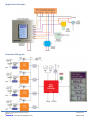
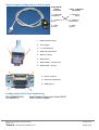
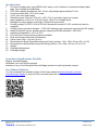
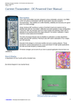
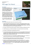
©danntech 2014
www.danntech.com
Smart Display User Manual
V2.00 –3rd March 2014
Smart Display User Manual
The Smart Display provides four independent and isolated digital displays with labeling for a variety
of process signals. It is convenient for local display of signals which may be routed to a central PLC
some distance from the transmitters.
A useful feature is that each analogue input is galvanically isolated from each other so that any four
process loops can be displayed without affecting each other or the measurement loop being
displayed.
The unit is panel mounted with the mounting arrangement to suit the application, up to IP66 if
required using suitable sealing gasket between the front mounting face and the panel.
Based on a 128 x 64 dot matrix LCD display, four analogue values can be scaled and displayed with
a general label and individual unit labels, precision and sign options. The backlit LCD display
dimensions are 38 x 70 mm resulting in a digit height of approximately 12 mm.
If you have any comments or suggestions which could improve this User Manual please e-mail them to me at
mailto:[email protected]?subject=Smart Display User Manual - Comment.
Application Example ........................................................................................................................... 3
Functional Diagram............................................................................................................................. 3
Installation .......................................................................................................................................... 4
For the Rear Clamp Mounting (rear fixing): .................................................................................. 4
For the Sealed Mounting (front fixing): ......................................................................................... 4
Configuring the Smart Display ............................................................................................................ 5
Setting up the Displayed Values and Units ......................................................................................... 6
Input Calibration ................................................................................................................................. 7
LEDs and Trimpot Adjustment Details ................................................................................................ 7
Smart Display Configuration Cable Details ......................................................................................... 8
Configuration Cable Part Numbering .................................................................................................. 8
Specifications ..................................................................................................................................... 9
Customised Applications Possible ...................................................................................................... 9
User Manual Updates ......................................................................................................................... 9
Part Numbering ................................................................................................................................ 10
Filename: Smart Display User Manual.docx
Version: 2.01
©
danntech
– PROCESS INSTRUMENTATION
27 March 2014
Page 1 of 10
Two mounting version are available –
Rear Clamp Mounting (rear fixing)
Filename: Smart Display User Manual.docx
Version: 2.01
©
danntech
– PROCESS INSTRUMENTATION
Sealed Mounting (front fixing)
27 March 2014
Page 2 of 10
Application Example
Functional Diagram
.
Filename: Smart Display User Manual.docx
Version: 2.01
©
danntech
– PROCESS INSTRUMENTATION
27 March 2014
Page 3 of 10
Installation
For the Rear Clamp Mounting (rear fixing):
The Smart Display depth required is approximately 60 mm from the rear of the front panel.
To fit the display:
1. Decide where in the panel you want to fit the unit.
2. Mark cut-out 104 x 114 mm (w x h).
3. Drill the corner holes inside the rectangle to be cut out and use a jig saw to neatly cut out the
rectangle.
4. Clean the cutout edges with a file.
5. Remove the rear fixing bracket and fit the Smart Display from the front and then refit the rear
fixing bracket.
6. Connect up the Smart Display.
For the Sealed Mounting (front fixing):
To fit the display:
Follow the same steps as above and in addition mark and drill the holes for the front fixing selftapping screws. Cut out and install a suitable gasket if required.
Filename: Smart Display User Manual.docx
Version: 2.01
©
danntech
– PROCESS INSTRUMENTATION
27 March 2014
Page 4 of 10
Configuring the Smart Display
The configuration software runs on any PC with all Windows operating systems. It requires a free
RS232 or USB port with Danntech-supplied, Smart Display Configuration Cable. (Cable details are
provided later in this user manual). A USB connection can be used with the USB to RS232 Adaptor.
(In the future we will be supplying a USB configuration cable).
The program SmartDisplayConfig.exe should be used to calibrate and configure the Smart Display.
This is available for downloading from our website (www.danntech.com) or should be on the CD in
the Danntech Software/Smart Display folder. This program does not require any installation and can
be run directly. It is better to run it from a location which is not write protected since it creates a
default configuration file which is saved to the directory from where it is run. This can be used to
rapidly configure displays with similar settings.
The simple steps are:
1. Connect up the Smart Display
Configuration Cable to a free
serial port.
2. Power up the Smart display.
3. Run the
SmartDisplayConfig.exe
program by double clicking on
the file or using Start | Run
“SmartDisplayConfig.exe” from
the desired location.
4. Use the Setup selection from
the menu at the top of the
Smart Display Config screen to
set the serial port being used.
5. In the Configuration section,
click on the “Read from unit”
button to transfer the Smart
Display Configuration to the
Smart Display Config program.
After a second or two you
should see the labels and units
update on your PC screen.
(Remember that if you change
anything it should be sent back
to the Smart Display by
clicking on the “Send to unit”
button).
6. In the Measurements section you can click on the “Read from unit” button to transfer the current
measurements to the Smart Display Config program. This can be done continuously each second
by selecting Auto Read – click on the box to select.
You can click onto any display parameter and, if it can be changed, a window will open allowing text
or numeric input. Note that any changes only come into effect in the Smart Display when the
configuration is sent to the unit. This is done by clicking on the “Send to unit” button in the
“Configuration” section.
If any communications problems occur, the status indicators below the “Read from unit” and “Send to
unit” buttons in the configuration section will change to red and change to “Error”.
Filename: Smart Display User Manual.docx
Version: 2.01
©
danntech
– PROCESS INSTRUMENTATION
27 March 2014
Page 5 of 10
Setting up the Displayed Values and Units
The Smart Display is shipped already having been calibrated so it should not be necessary to set
(Latch) the A to D Zero or Full Scale values. If you click on either of these buttons you will overwrite
the input calibration for that channel and you will have to recalibrate the input. If you want to
experiment – save the configuration to a file and then you can restore it later. The calibration is
described in the next section.
When setting up an input click on the input text (in this example “Weighbridge”), a text window will
open. Type in the text you wish to be displayed and then click “OK”. The input display units are
changed in the same way – just click on the units text (in this example “kg”) and enter the units
required. (Note that no changes are effected to the Smart Display until the new configuration is sent
to the unit – this can be done at the end).
You should now select where you want the decimal point – you should do this before changing the
engineering units.
Now click on the “Engineering Units Zero” value and enter the value to be displayed for the minimum
input (normally 4 mA for a 4-20 mA input). Do the same for the “Engineering Units Full Scale” value
(normally 20 mA for a 4-20 mA input).
Note that the zero and full scale values need not necessarily be the minimum and maximum – it
could be done at 6 and 18 mA, for example, provided that the calibration has been done at these
values. Basically the Smart Display maps whatever the minimum calibration A to D input is to the
“Engineering Units Zero” value and the maximum calibration A to D Input to the “Engineering Units
Full Scale” value.
(The way the inputs are set up is a cool feature – in that, if your sensor or transmitter output is say
4.5 mA at 0% and say 19.8 mA at 100% you can accommodate this by setting the capturing the
minimum and maximum values and then scaling the display to these values)
Filename: Smart Display User Manual.docx
Version: 2.01
©
danntech
– PROCESS INSTRUMENTATION
27 March 2014
Page 6 of 10
Input Calibration
Allow the Smart display to reach operating temperature – leave running for an hour or so before
doing the calibration.
Inject the minimum input value, typically 4.00 mA, using a stable current source. Allow the “A to D
Input” value to settle and then click on the “Set” button to latch the “A to D Input Zero” value. Normally
this would be in the range 50 to 200 for a 4.00 mA input.
Inject the maximum input value, typically 20.00 mA, using a stable current source. Allow the “A to D
Input” value to settle and then click on the “Set” button to latch the “A to D Input Full Scale” value.
Normally this would be in the range 900 to 1050 for a 20.00 mA input.
LEDs and Trimpot Adjustment Details
Filename: Smart Display User Manual.docx
Version: 2.01
©
danntech
– PROCESS INSTRUMENTATION
27 March 2014
Page 7 of 10
Smart Display Configuration Cable Details
9 Way DSUB
Female
Connector
8 way Telephone
Connector
2 – RS232 Rx
(white/blue)
4 – RS232 Rx
(blue)
3 – RS232 Tx
(blue)
5 – RS232 Tx
(white/blue)
5 – GND
(green)
6 - GND
(green)
1 – PROG (white/orange)
2 – 0 V (orange)
3 - +5 V (white/green)
4 – RS232 Rx (white/blue)
5 – RS232 Tx (blue)
6 – GND (green)
7 – RS485 Data + (white/brown)
8 – RS485 Data – (brown)
2 – RS232 Tx (blue)
3 – RS232 Rx (white/blue)
5 – GND (green)
Configuration Cable Part Numbering
SD-CCABLE/RS232
PI-USB/RS232
Smart Display Configuration Cable RS232
USB to RS232 Adaptor
Filename: Smart Display User Manual.docx
Version: 2.01
©
danntech
– PROCESS INSTRUMENTATION
27 March 2014
Page 8 of 10
Specifications
1.
2.
3.
4.
5.
6.
7.
8.
9.
10.
11.
12.
13.
14.
15.
16.
17.
18.
19.
PC based configuration using RS232 and “easy to use” software to customize display label,
tags, input scaling and calibration.
LCD active display dimensions 38 x 70 mm, digit height approximately 12 mm.
Accuracy better than 0.2% of full scale.
±10% over and under-range.
Standard inputs 0-20 mA, 4-20 mA, ±10V, 0-10 V and other inputs on request.
Input resistance of 50 Ω for 4-20 mA inputs, 100 kΩ for voltage inputs.
Backlight for clear display in low light, industrial environments.
Auxiliary supply 24 VDC ±10% at 200 mA (by special request 12 VDC models can also be
supplied).
Auxiliary power galvanic isolation > 1000 VAC between each analogue input and the DC supply.
Isolation between inputs, auxiliary power supply and RS485 interface >1000 VAC.
Operating temperature -10°C to 70°C.
Front and rear fixing mounting options available.
Rear access screw terminal connections.
Panel cutout 104 x 114 mm (W x H).
Dimensions for Rear Clamp Mounting (rear fixing) version: 110 x 120 x 62 mm (W x H x D).
Dimensions for Sealed Mounting (front fixing) version: 150 x 160 x 62 mm (W x H x D).
Weight
Packaged dimensions
Packaged weight
Customised Applications Possible
Display and data logging.
Dedicated, low cost control systems.
Interface to any of the Danntech Remote Magic products to add inputs and outputs.
User Manual Updates
You can download the updated version of this user manual at www.danntech.com/user
manuals/smart display or scan the QR code and follow the link.
Filename: Smart Display User Manual.docx
Version: 2.01
©
danntech
– PROCESS INSTRUMENTATION
27 March 2014
Page 9 of 10
Part Numbering
SD-x/a1b1 a2b2 a3b3 a4b4/n
Smart Display
Where:
x = R – this is the Rear Clamp Mounting (rear fixing) option with back fastening clamp
x = S – this is the Sealed Mounting (front fixing) option with brushed stainless steel face for front
panel waterproof usage.
a = V: voltage input
a1b1 = input type for Input 1, a = I: current input
a2b2 for Input 2,
b: A = 4 to 20 mA
b: A = 0 to 10 V
a3b3 for Input 3 and
B = 0 to 20 mA
B = 0 to 50 mV
a4b4 for Input 4.
M=0-1A
C = ±50 mV
N=0-5A
P = 0 - 10 A
Q = 0 – 15 A
(other ranges on request)
D = 0 to 5 V
E = ±5 V
F = 1 to 5 V
G = ±10 V
H = 0 - 100 mV
T = 0 - 15 V
M = 0 - 30 V
Y = 0 - 100 V
(other ranges on request)
n = auxiliary supply
n = C: 24 VDC
D: 12 VDC
Typical part numbers and descriptions:
SD-S/IAIAIAIA/C
Smart Display 4-20mA/4-20mA/4-20mA/4-20mA 24VDC Sealed
SD-R/IAIAIAIA/C
Smart Display 4-20mA/4-20mA/4-20mA/4-20mA 24VDC R Fix
SD-R/VAVBIAIA/C
Smart Display 0-10V/0-50mV/4-20mA/4-20mA 24VDC R Fix
danntech Ltd
danntech cc
Co. No. 6510211
15 College Close, Hamble-le-Rice
Southampton, Hampshire
SO31 4QU
United Kingdom
Tel: 075 9069 1824
Reg. No. CK1986/15338/23
Tel International: +27 11 7921239
Tel National: 011 7921239
Fax International: +27 11 7924687
Fax National: 011 7924687
e-mail: [email protected]
e-mail: [email protected]
www.uk.danntech.com
P O Box 1023, Fontainebleau, 2032
Republic of South Africa
www.danntech.co.za
Danntech makes no warranty of any kind with regard to this material, including, but not limited to, the implied warranties of merchantability and fitness for a particular purpose.
Danntech shall not be liable for errors contained herein or for incidental or consequential damages in connection with the furnishing, performance or use of this material. This
document contains proprietary information, which is protected by copyright. No part of this document may be photocopied, reproduced, or translated into another language
without the prior written consent of Danntech. The information in this document is subject to change without notice.
Filename: Smart Display User Manual.docx
Version: 2.01
©
danntech
– PROCESS INSTRUMENTATION
27 March 2014
Page 10 of 10