1
USER MANUAL
AX2010P
passive ver cal array loudspeaker
KEY FEATURES
• High output line array element
• Compact size, very good output-to-weight ra o
• High quality, low compression, low distor on HF driver
• Very stable horizontal coverage
• Transmission Line back loading for clean mid-bass reproduc on
• Natural sound Transmission Line HF projec on wave-forming device
INTRODUCTION
The AX2010P Ver cal Line Array element is designed for a wide range of sound reinforcement applica ons where a flexible and easy to use ver cal
array systems is needed. The AX2010P has been designed both for rental live sound applica ons and for fixed installa ons and has been engineered
for the simplest use possible but without sacrificing anything in sound quality and performance.
The high frequency range is reproduced by two low-distortion
compression drivers, equipped with very light-weight diaphragms. Two
transmission line waveforming waveguides have been used to load
the HF drivers, in order to provide a detailed and natural sound and to
achieve a long-distance HF projec ng capacity.
The two 10” woofers employed in the reproduc on of the mid-bass
range are equipped with very light-weight cones. The lightness of the
diaphragm is furthermore improved by the use of aluminium voice coil
instead of conven onal copper. This ensure a fast reproduc on of the
mid range and of mid-bass musical passages, improving also the thermal
capacity of the voice coil and, consequently, controlling the overall power compression. The two
10” woofers are back loaded by a short hybrid transmission line that minimizes the effect of the box
resonances and eliminates the “boxy” mid-bass sound commonly obtained from regular bassreflex enclosures.
The crossover filter approach is based on a “Constant Power” technique. Thanks to a par cular phase combina on between the two ways around
the crossover frequency, this approach is able to provide a very stable horizontal coverage and a very stable off-axys sound image, also minimizing
unwanted effects around the crossover frequency. The further applica on of phase lineariza on techniques, combined to constant power crossover,
yield a linear phase response and a coherent me response. This allows for a natural percep on of acous c instruments and voices and for an
improved depth of the sound image.
TECHNICAL SPECIFICATION
Acous cal
System type
Line Array Element
Short Transmission Line LF Back Loading
Acous c Transmission Line HF Waveguide
Low frequency transducer
Two 10” (260 mm), 2.5” (64 mm) aluminium
voice coil, 16Ω each, paralleled
High frequency transducer
Two 1.4” drivers, 2.5” (64 mm) edgewound
voice coil, tanium diaphragm,
16Ω each, paralleled
Frequency response (±3 dB)
Sensi vity (2.83 V @ 1m, 2 Pi)
Horizontal Coverage Angle
Ver cal Coverage Angle
Maximum Peak SPL @ 1m
Electrical
Nominal Impedance
Power Handling Con nuous*
8Ω (LF) + 8Ω (HF)
700 W (LF) + 150 W (HF)
Power Handling Peak
1400 W (LF) + 300 W (HF)
LF Power Compression
@ -10 dB Power (70 W) = 0.5 dB
@ -3 dB Power (350 W) = 1.5 dB
@ 0 dB Power (700 W) = 3.2 dB
* AES Pink Noise Power
75 Hz – 18 kHz (Processed)
99 dBSPL (LF); 108 dBSPL (HF)
110° (-6 dB)
10° (-6 dB)
130 dB
Connectors
Connector Type
Input Wiring
Mechanical
Width
Height
Depth
Taper angle
Construc on
Paint
Suspension system
Front Suspension
Back Suspension
Net Weight
Neutrik® Speakon® NL4 x 2
LF = Pin 1+/1-; HF = Pin 2+/2746 mm (29.37”)
341 mm (13.42”)
530 mm (20.86”)
5°
15 mm, reinforced Phenolic Birch
High resistance, water based paint
Aluminium Fast Link structure with ¼ Fast Pin
High Strength Steel with ¼ Fast Pin
39.9 Kg (87.96 lbs.)
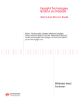
MECHANICAL DRAWING
230 mm
9.06"
5.0°
OPTIONAL ACCESSORIES
AXCASE02
Carrying Case for 2 box unit
NL4FX
Neutrik Speakon® PLUG
PC260
2 in 6 out digital loudspeaker processor
USB2CAN
PRONET network converter
RAINCOV2010
Rain protec on for connectors
KPTAX2012P
Fly bar for Axiom AX2010 Loudspeakers
BOARDAC2P
M10 foot for stacked installa on
see www.proel.com for detailed descripƟon and other available accessories.
SPARE PARTS
NL4MP
Neutrik Speakon® panel socket
95AXM014
Locking Pin for AX2010
PLG716
Straight Shackle 16 mm for Fly bar
91CRAIN3
Crossover/protec on module
98AXM10WZ8
10’’ woofer - 2.5” VC
98DRI1424
1.4’’ - 2.5” compression driver
98MBN1424
tanium diaphragm for 1.4” driver
341 mm
13.42”
746 mm
29.37”
530 mm
20.86”
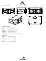
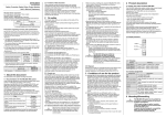
REAR PANEL
INPUT - Power input for the external amplifier. The AX2010P does not include a passive crossover for filtering the signal, but only an internal
protec on that applies a gentle high-pass filtering and a limita on for excessive power on the HF sec on. The connec ons are the following:
INPUT - LINK
NL4 pin number
internal connec on
1+
LF+
1-
LF-
2+
HF+
2-
HF-
LINK - Power output in parallel with the INPUT socket for connec ng the unit to another speaker. The number of AX2010P cabinets that can be
connected in parallel depends on the amplifier load capacity.
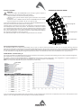
AIMING and SUSPENDING INSTRUCTIONS
PREDICTION: EASE Focus 1
To aim correctly a complete system PROEL suggests to use always the Aiming
So ware - EASE Focus 1:
The EASE Focus 1 Aiming So ware is a two-dimensional, acous c simula on
so ware that serves for the configura on and modelling of Line Arrays close to
reality. It only considers the direct field, created by the complex addi on of the sound contribu ons of the individual loudspeakers or array
components.
The design of EASE Focus is targeted at the end user. It allows the easy and quick predic on of the array performance in a given venue. The scien fic
base of EASE Focus stems from EASE, the professional electro- and room acous c simula on so ware developed by AFMG Technologies GmbH. It
is based on the EASE Focus 1 system defini on files (Proel_AXIOM_AX2010P.EFO) required for its use. The EFO file contains the data that defines
the Line Array with regard to its possible configura ons as well as to its geometrical and acous cal proper es. For detailed explana on of how to
use the so ware and how to obtain a correct aiming refer to EASE Focus documenta on and other on-line manuals (h p://focus.afmg.eu/index.
php/Focus_1.html).
WARNING! CAREFULLY READ THE FOLLOWING INSTRUCTIONS AND CONDITION OF USE:
• This loudspeaker is designed exclusively for Professional audio applica ons. The product must be installed by qualified personal only.
• Proel strongly recommends that this loudspeaker cabinet be suspended taking into considera on all current Na onal, Federal, State and
Local regula ons. Please contact the manufacturer for further informa on.
• Proel do not accept any liability for damage caused to third par es due to improper installa on, lack of maintenance, tampering or
improper use of this product, including disregard of acceptable and applicable safety standards.
• During assembly pay a en on to the possible risk of crushing. Wear suitable protec ve clothing. Observe all instruc ons given on the
rigging components and the loudspeaker cabinets. When chain hoists are in opera on ensure that there is nobody directly underneath or
in the vicinity of the load. Do not under any circumstances climb on the array.
KPTAX2012P Fly Bar and accessories
The AX2010 Systems are built to allow the suspension of array with variable shape and dimensions. Thanks to a suspension mechanism designed
to be func onal, flexible and safe, each system must be suspended or stacked using the KPTAX2012P fly bar. The loudspeakers are linked together
in a column using a series of couplers integrated in the frame of each enclosure. Each system is set up properly both acous cally and mechanically
only using the aiming so ware.
Coupling system in the front does not require any adjustment: using two locking pins, each loudspeaker box is fixed to the previous. The slo ed
bar in the back is inserted in a U-shaped frame which features a series of numbered holes. Sliding the slo ed bar in the U-shaped frame of the
next loudspeaker and inser ng a locking pin in one of the numbered holes, it is possible to adjust the rela ve splay angle between two adjacent
loudspeakers in the array column.
KPTAX2012P fly bar maximum capacity is 700 Kg (1540 lbs) with the 0° angle. It can support up to 12 AX2010 loudspeakers with a safety factor
of 7:1.
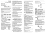
KPTAX2012P FLY BAR AND ACCESSORIES
M10 FOOT FOR
STACKED INSTALLATION
(OPTIONAL)
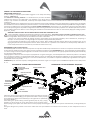
KPTAX2012P FLY BAR ASSEMBLY SEQUENCE
STRAIGHT SHACKLE 16mm
1
IDENTIFICATION AND
DATA LABEL
5
1
2
FRONT BOX
PIN ATTACHMENT
3
SUSPEND HOLE
INDICATOR
SUSPEND HOLES
2
FRONT BOX
PIN ATTACHMENT
REAR BOX
PIN ATTACHMENT
4
Follow the sequence in the figure for fixing the fly bar at the first box. Usually
this is the first step before li ing up the system. Be careful to insert properly
all the locking pins (2)(3) and the shackle (5) in the right holes as specified by
the aiming so ware.
When lifting the system always proceed gradually step by step, paying
a en on to secure the fly bar to the box (and the box to the other boxes)
before pulling up the system: this makes easier to insert properly the locking pins. Also when the system is released down, unlock gradually the
pins.
During the li ing be very careful to not let the cables enter the space between one enclosure and the other, as their compression could cut
them.
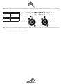
Fly bar suspension and angle setup (centre of gravity)
The first figure shows where the normal centre of gravity is with one box or several boxes arranged in a line. Usually the boxes are arranged to
make an arc for the best coverage of the audience, so the center of gravity moves backward. The aiming so ware suggests the ideal suspension
pinpoint taking into account this behaviour: fix the straight shackle in this posi on.
KPTAX2012P FLY BAR FOR FLOWN ARRAY
KPTAX2012P FLOWN PINPOINT
SINGLE PINPOINT FOR
STRAIGHT SHACKLE
Note that the ideal aiming angle o en doesn’t correspond to the pinpoint: there
is o en a li le difference between ideal aiming and real aiming and its value is
the remaining angle: posi ve remaining angle can be adjusted a li le using two
ropes, nega ve remaining angle are self adjusted a li le because the cables
weighs on the back of the array. With some experience it’s possible to consider
preven vely these required li le adjustments.
CENTRE OF GRAVITY
During the flown set up you can connect the elements of the array to their cables.
We suggest to discharge the weight of the cables from the flying pinpoint by tying them with a tex le fibre rope, instead of le ng them hang
freely: in this way the posi on of the array will be much more similar to the simula on produced by the so ware.
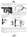
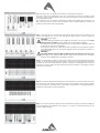
Pin locking and splay angles set up
The figure below shows how to insert correctly the locking pin and how to set up the splay angle between loudspeakers.
95AXM014 LOCKING PIN
LOUDSPEAKER SPLAY ANGLES SET UP
HINGE BAR OF PREVIOUS BOX
Odd degrees
LOCK THE PIN IN THE
HOLE TO OBTAIN THE
REQUIRED SPLAY
ANGLE.
press and
insert
3° >
5° >
release and
lock
7° >
9° >
Degrees
indicator >
1° STEP HOLE
0,5° STEP HOLE
0°
1°
2°
1° >
Block cam
hole >
Even degrees
3°/0,5°
< 2°
< 4°
< 6°
< 8°
4°/1,5°
5°/2,5°
6°/3,5°
Pin
7°/4,5°
8°/5,5°
9°/6,5°
10°
< 10°
< 0°/10°
< 0,5°/6,5°
USE THIS HOLE TO
LOCK THE HINGE BAR
WHEN THE LOUDSPEAKER
IS REST
Block cam
hole
Wind loads
When planning an open-air event it is essen al to obtain current weather and wind informa on. When loudspeaker arrays are flown in an open-air
environment, possible wind effects must be taken into account. Wind load produces addi onal dynamic forces ac ng on the rigging components
and the suspension, which may lead to a dangerous situa on. If according to the forecast wind forces higher than 5 b (29-38 Km/h) are possible,
the following ac ons have to be taken:
- The actual on-site wind speed has to be monitored permanently. Be aware that wind speed typically increases with height above ground.
- Suspension and securing points of the array should be designed to support double the sta c load in order to withstand any addi onal dynamic
forces.
WARNING!
Flying loudspeakers overhead at wind forces higher than 6 b (39-49 Km/h) is not recommended. If the wind force exceeds 7 b (50-61
Km/h) there is a risk of mechanical damage to the components which may lead to a dangerous situa on for persons in the vicinity of the
flown array.
- Stop the event and make sure that no person remains in the vicinity of the array.
- Lower and secure the array.
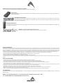
Stacked installa on
KPTAX2012P STACKED ARRAY
WARNING!
• The ground where the KPTAX2012P Fly bar serving as ground support is
placed needs to be absolutely stable and compact.
• Adjust the feet so to lie the bar perfectly horizontal.
• Always secure ground stacked setups against movement and possible
pping over.
• A maximum of 4 x AX2010 cabinets with the KPTAX2012P Fly bar serving
as ground support are allowed to be set up as ground stack.
max splay angle 10°
In the stack configura on you have to use the three op onal BOARDAC2P feet and
the fly bar must be mounted upside down on the ground.
Coupling system in the front do not require any adjustment: using two locking pins
each loudspeaker box is fixed to the previous. The slo ed bar in the back is inserted
in a U-shaped frame which features a series of numbered holes. Sliding the slo ed
bar in the U-shaped frame of the next loudspeaker and inser ng a locking pin in
one of the numbered holes, it is possible to adjust the rela ve splay angle between
two adjacent loudspeakers in the array column.
The op mal splay angles can be simulated using the EASE Focus 1 so ware.
max splay angle 10°
max splay angle 10°
max splay angle 5°
CENTER OF GRAVITY
System Processing basic instruc on
The AX2012P system do not feature passive filters and, to work, it needs an external processor to take care of crossover filtering, temporal
alignment and protec on of all devices. Proel provides PC260 digital processor which comes with the basic preset for the AX2010. The op miza on
of ver cal array systems through digital processing is based on data obtained through measurements of the polar response throughout space and
on their elabora on through purpose-designed mathema cal models. For detailed instruc ons about PC260 refer to its proper manual.
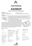
PC260 PRESET: 2-F-2010-4T1S_02
The preset provided for the AX2012P allow the correct opera on of the system, provide the best star ng point for setup of temporal alignment,
gain adjustment and, eventually, system equaliza on.
The preset is made considering 8xAX2010P and 2xSW218P for each column in flown configura on, this configura on is a typical applica on of
AX2010P ver cal array so for the flown array arrangement was considered similar to the following:
NOTE: The subwoofers SW218P was placed underneath the flown array.
SystemDetails
Company:
SystemSetup:
PickPoint:
PROEL
Axiom_AX2010P
X=1,50m
Y=8,00m
Ͳ6,35°
10(RemainingAngle=0,00°)
8,30kg("KPTAX201P")
319,20kg("AX2010P")
327,50kg
2,65m
CradleAngle:
PinPoint:
FrameWeight:
BoxWeight:
TotalWeight:
Height:
RiggingDetails
Nr.
Box
Gain
Angle
Total
Frame
1
2
3
4
5
6
7
8
KPTAX201P
AX2010P
AX2010P
AX2010P
AX2010P
AX2010P
AX2010P
AX2010P
AX2010P
0dB
0dB
0dB
0dB
0dB
0dB
0dB
0dB
0
1
1
2
2
3
4
6
Ͳ6,35
Ͳ6,35°
Ͳ7,35°
Ͳ8,35°
Ͳ10,35°
Ͳ12,35°
Ͳ15,35°
Ͳ19,35°
Ͳ25,35°
In the “2-F-2010-4T1S_02” PC260 preset some parameters can be customized and some other are protected, this ensure a safe opera on of the
system. In the next page follows a brief descrip on of customizable parameters:
IN: In this screen you can adjust the input levels and the input compressors.
The input range can be op mized in the -30 ÷ +6 dB range. The level is set a er the AD
conversion, so if you have problems with an excessive input signal use the analog PAD bu on
on the PC260 back panel.
The compressors are set in order to a enuate very high input signals (the threshold is +11
dB), ensuring a more transparent musical behaviour of the system limi ng. If needed, the
compressor threshold can be freely adjusted.
OUT: in this page you can see the level of the output signals and the gain reduc on if the
limiters are ac vated. You can also trim (±6 dB) the output signals in order to adjust the
balance of LF, MF and HF ranges.
WARNING!
The limiter se ng of PC260 and 2-F-2010-4T1S_02 preset is set for the use of 32 dB
fixed gain power amplifiers: contact PROEL if you need a different se ng.
The delays are set for the op mal alignment of a standard flown configura on with the
ver cal array on top of the subwoofers.
If needed, the delay of the subwoofers (LOW-L and LOW) can be adjusted in rela on
to the MID-HIGH outputs for the op mal alignment when the system is installed in a
different posi on.
WARNING!
The DELAY difference between MID and HIGH outputs must always be 14.3 mm (HIGH
before MID). If you modify the MID delay to align the tops with the subs, remember
always to set the HIGH delay accordingly (-14.3 mm).
GEQ: this is the graphic equalizer on the processor inputs to be used for equalizing the whole
system. It can be used for adjus ng the system’s response or for fixing par cular frequency
problems in the environment where the system is installed. The AX2010P preset has been
prepared in order to obtain the best performance from the system, so we suggest to avoid
extreme use of the GEQ.
PEQ: this is a full parametric 5-band equalizer on the processor’s inputs. Each filters can be set
also as shelving, notch, allpass, high-pass and lo-pass, so this equalizer can be used to op mize
the system response according to the environment characteris cs, including temperature,
humidity and absorp on due to the audience.
DEQ: this is 3-band dynamic equalizer useful to op mize the system’s response for different
kind of applica ons and different music genres, or to obtain an op mal behaviour of the
system at different levels.
Useful tools to set up properly a ver cal array system
This is a list of tools that can be very useful to set properly a ver cal array system.
CABLE TESTER
It is a good prac ce to check all cables before each installa on, because even one faulty cable can compromise heavily the
system performance.
INCLINOMETER WITH LEVER
This tool can be used to verify the ver cal array angle. It can be used at the top or at the bo om of the array In this
case you have to sum all splay angles, so the maximum precision is needed for aiming the ver cal array, par cularly
for long throw applica ons.
LASER DISTANCE METER
This instrument can be useful to measure the height of the ver cal array and to know the distance between FOH-Subs and FOH-Array
for se ng the delay me.
SMAART or similar acous c measurement system
These are useful to measure delays, phase and response of the system.
LIMITED WARRANTY
Proel warrants all materials, workmanship and proper opera on of this product for a period of two years from the original date of purchase. If any defects are found
in the materials or workmanship or if the product fails to func on properly during the applicable warranty period, the owner should inform about these defects the
dealer or the distributor, providing receipt or invoice of date of purchase and defect detailed descrip on. This warranty does not extend to damage resul ng from
improper installa on, misuse, neglect or abuse. Proel S.p.A. will verify damage on returned units, and when the unit has been properly used and warranty is s ll
valid, then the unit will be replaced or repaired. Proel S.p.A. is not responsible for any “direct damage” or “indirect damage” caused by product defec veness.
• This unit package has been submi ed to ISTA 1A integrity tests. We suggest you control the unit condi ons immediately a er unpacking it.
• If any damage is found, immediately advise the dealer. Keep all unit packaging parts to allow inspec on.
• Proel is not responsible for any damage that occurs during shipment.
• Products are sold “delivered ex warehouse” and shipment is at charge and risk of the buyer.
• Possible damages to unit should be immediately no fied to forwarder. Each complaint for package tampered with should be done within eight days from product
receipt.
SAFETY INSTRUCTIONS
– To reduce the risk, close supervision is necessary when the product is used near children.
– Protect the apparatus from atmospheric agents and keep it away from water, rain and high humidity places.
– This product should be site away from heat sources such as radiators, lamps and any other device that generate heat.
– This product should be located so that its loca on or posi on does not interfere with its proper ven la on and hea ng dissipa on.
– Care should be taken so that objects and liquids do not go inside the product.
– The product should be connected to a power supply mains line only of the type described on the opera ng instruc ons or as marked on the product. Connect the
apparatus to a power supply using only power cord included making always sure it is in good condi ons.
– WARNING: The mains plug is used as disconnect device, the disconnect device shall remain readily operable.
– Do not cancel the safety feature assured by means of a polarized line plug (one blade wider than the other) or with a earth connec on.
– Make sure that power supply mains line has a proper earth connec on.
– Power supply cord should be unplugged from the outlet during strong thunderstorm or when le unused for a long period of me.
CE CONFORMITY
Proel products comply with direc ve 2004/108/EC (EMC), as stated in EN 55103-1 and EN 55103-2 standards and with direc ve 2006/95/CE (LVD), as stated in EN
60065 standard.
PROEL S.p.A. (World Headquarter) - Via alla Ruenia 37/43 - 64027 Sant’Omero (Te) - ITALY
Tel: +39 0861 81241 Fax: +39 0861 887862 www.proel.com