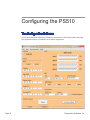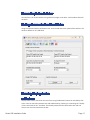
1
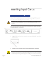
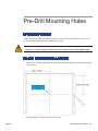
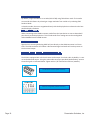
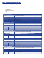
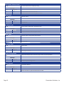
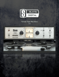
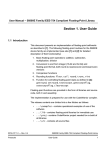
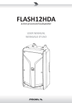
Presentation
Switchers
Series 500
Installation Guide
PS510
Under Table
Presentation Switcher
October, 2012 • PN: DOC-000005-00A
Trademark Informa on
Presenta on Switchers®, the “PS Box” logo or icon, and the names and marks associated with Presenta on
Switchers’ products are trademarks and/or service marks of Presenta on Switchers, Inc., and are registered
and/or common-law marks in the United States and various other countries.
All other trademarks are the property of their respec ve owners.
Patent Informa on
The accompanying product is protected by one or more U.S. and foreign patents and/or pending patent
applica ons held by Presenta on Switchers, Inc.
Customer Feedback
We are constantly working to improve the quality of our documenta on, and we would appreciate your
feedback. Please send email to markeƟng@PresentaƟonSwitchers.com.
© 2012 Presenta on Switchers, Inc. All rights reserved.
Presenta on Switchers, Inc.
15364 E. Valley Blvd.
City of Industry, CA 91746 USA
No part of this document may be reproduced or transmi ed in any form or by any means, electronic or
mechanical, for any purpose, without the express wri en permission of Presenta on Switchers, Inc. Under
the law, reproducing includes transla ng into another language or format.
Every effort has been made to ensure that the informa on in this manual is accurate. Presenta on Switchers, Inc., is not responsible for prin ng or clerical errors.
Informa on in this document is subject to change without no ce.
Page 2
Presentation Switchers, Inc.
Contents
Contents ............................................................................................3
Getting Started..................................................................................5
Installation Guide Overview ..................................................................................................... 5
Package Contents ..................................................................................................................... 5
Installation Tools ....................................................................................................................... 5
Inserting Input Cards .......................................................................6
Inserting an Input Board Assembly ......................................................................................... 6
Pre-Drill Mounting Holes..................................................................8
Locating the Switcher ............................................................................................................... 8
Pre-Drill Mounting Holes As Shown ........................................................................................ 8
Connecting Devices .........................................................................9
Input Devices / Sources ............................................................................................................ 9
Connecting Display or Video Output Devices ........................................................................ 9
Connecting Audio Output Devices ........................................................................................ 10
Connecting Control Devices .................................................................................................. 11
Configuring the PS510 ...................................................................12
The Configuration Software ................................................................................................... 12
Uploading the Settings ........................................................................................................... 14
Save or Retrieve Settings ....................................................................................................... 14
PS500 Display Control ...................................................................15
Main Form ................................................................................................................................ 15
Relay Form ............................................................................................................................... 16
Test Form ................................................................................................................................. 16
Connecting to the Switcher .................................................................................................... 17
Setting Communication Baud Rates ..................................................................................... 17
Entering Display Codes .......................................................................................................... 17
Input Select .............................................................................................................................. 18
No Signal Power Off ................................................................................................................ 18
Time Between Commands...................................................................................................... 18
No Activity Power Off.............................................................................................................. 18
Series 500 Installation Guide
Page 3
Relay / Contact Closure Enable Flag ..................................................................................... 19
Mode ......................................................................................................................................... 19
Testing the Display Codes...................................................................................................... 20
Testing the Relays ................................................................................................................... 20
Testing the Complete System ................................................................................................ 21
Enabling or Disabling the Display Control Feature ............................................................. 21
Appendix .........................................................................................22
Series 500 Programming Codes ............................................................................................ 23
Page 4
Presentation Switchers, Inc.
Getting Started
Installation Guide Overview
This manual will provide detailed instruc ons to assist an installer with a typical under table installa on of a PS510 presenta on switcher. This process is best outlined by the following steps.
1. Unpack the switcher from the box and separate all components.
2. Install input cards (if necessary)
3. Locate and pre-drill moun ng holes.
4. Mount the switcher under the table.
5. A ach input and output devices to the switcher.
6. Power up the unit and test the unit manually.
7. Make adjustments to the system as necessary.
8. Test the system again using external control devices as necessary.
Package Contents
Below is a list of items enclosed in each Series 500 enclosure.
Quantity
Description
1
PS510 Presentation Switcher
1
Installation Guide (PN: DOC-000005-xxx) (This manual)
1
5 Connector Terminal Block Stereo Audio Connector, Line Level Audio
6
Wood Screws, #6 X 3/4”, Pan-Head, Philips
1
Power Cord (US Only)
Installation Tools
•
•
•
•
Drill
3/32” Drill Bit for So wood or 7/64” Drill Bit for Hardwood
#2 Philips Head Screw Driver
1/8” Flat Blade “Tweeker” Screw Driver
Series 500 Installation Guide
Page 5
Inserting Input Cards
Inserting an Input Board Assembly
In the United States and Canada, input cards are installed prior to leaving the factory. In some
countries cards are shipped separately. This sec on explains the process necessary to install
input card assemblies into a PS510 presenta on switcher.
WARNING: While “hot swapping” of input cards is possible, it is recommended to disconnect power from the PS510 enclosure to prevent accidental shock to yourself or to the
equipment.
The drawing below shows a sample layout of a PS510 enclosure. In this case, the system type is
a PS510 with HDMI, DVI, and VGA inputs.
1. Using a #1 Philips Head screw driver, remove the screw that holds the IN500 - Future Expansion Plate in place.
2. Unpackage the new input board assembly from the shipping container and set aside.
CAUTION: This product, like all microcontroller products, uses semiconductors that can be
damaged by electrosta c discharge (ESD). When handling, care must be taken so that the device is not damaged. Damage due to inappropriate handling is not covered by the warranty.
Page 6
Presentation Switchers, Inc.
The following precau ons must be taken.
a. Do not open the protec ve conduc ve packaging un l you have read the following, and
are at an approved an -sta c work sta on.
b. Always discharge yourself by touching a grounded bare metal surface before picking up
an ESD - sensi ve electronic component.
3. Remove the input board assembly from the protec ve conduc ve packaging.
4. Insert the new input board assembly into the enclosure while aligning card within the
guides on the le and right of the opening. Press the card firmly (about 10 lbs of force) into
the card slot.
5. Using the screw extracted from the IN500 Future Expansion plate, fasten the new input
board assembly in place.
6. Connect power cord to enclosure and turn system on.
7. The system is now ready for use and the new input is ac ve.
Series 500 Installation Guide
Page 7
Pre-Drill Mounting Holes
Locating the Switcher
Locate the switcher under the table toward the center line of the table. Ensure switcher is far
away from poten al contact with people’s legs or knees.
WARNING: Keep product away from poten al contact with human legs, knees, and other
body parts. A PS510 is made of metal and can harm people if struck with sufficient force.
Pre-Drill Mounting Holes As Shown
1. Using a 3/32” drill (for so wood) or 7/64” drill (for hardwood), drill each hole approximately
5/8” in depth.
Center Line of
PS510
2. Using #2 Phillips screw driver, fasten all 6 screws.
Page 8
Presentation Switchers, Inc.
Connecting Devices
Input Devices / Sources
Connect input devices or audio-visual sources as you would most AV Receivers. In most cases,
one source is connected per input board assembly and includes both the video and audio components.
3.5mm Connector
In the example above, a DVI-D board, part number IN504 in this case, is located in input slot
number 2. Connect the video por on to the DVI connector and the audio component to the
3.5mm connector located just above the video connector. This device is now considered “Input
#2”.
Note: The LED located just above the stereo connector will illuminate red when power is
present on the card. The LED will illuminate green when an ac ve video signal is recognized
on the DVI video connector. This LED is present on most input board assemblies.
Con nue the process of connec ng input devices un l all sources are a ached.
Connecting Display or Video Output Devices
The PS510 presenta on switcher is equipped with HDMI and VGA connectors. These connectors
are located on the opposite side of the input card assemblies.
The HDMI and VGA outputs are simultaneous outputs and output the same resolu ons at all
mes.
Series 500 Installation Guide
Page 9
EDID and Image Resolu ons
By default, image resolu on is set to XGA (1024 X 768) using Table Select mode. The installer
can override this feature by selec ng an image resolu on from a table or by selec ng EDID
Passthru Mode.
In Passthru mode, the source nego ates directly with the display device to determine the best
possible display resolu on.
Audio on HDMI Connector
When connec ng to the HDMI connector, audio from the input device or source selected will
pass directly to the display device. This includes audio from analog sources that are digi zed
and embedded onto the HDMI stream.
HDCP Encrypted Sources
Signals which are encrypted using HDCP will pass directly to the HDMI connector in all situaons. The VGA connector will indicate a disconnected signal and audio will not be present on
the Line Level output.
Connecting Audio Output Devices
The PS510 is equipped with a line level stereo audio output. Line level audio, by default, is a stereo audio balanced output. Using the male audio connectors provided (shown below), connect
the audio signals as indicated below. Tighten with a 1/8” flat head screw driver (tweeker).
Line Out Audio Connector (Male Connector)
Audio Pin Configuration (Female Connector)
Page 10
Presentation Switchers, Inc.
Connecting Control Devices
In addi on to the standard front panel controller, the Series 500 provides addi onal control
methods. Serial (RS-232) and Ethernet provides connec on to third-party controllers such as
Crestron and AMX.
Crestron or AMX Control Systems
Connec on to a 3rd party (AMX/Crestron etc) control system can be accomplished using RS232
or Ethernet. Se ngs can be adjusted using the Configura on U lity discussed in more detail
later in this guide.
The default baud rate for the serial port is 115200.
Display Control
The PS510 has a simple control system for controlling a display device (LCD, Plasma, or Projector). The serial port is connected directly to the display device. Codes are uploaded and stored
in the PS510 using the PS500 Display Control U lity. When the system is shutdown and a input
source is selected the projector is sent a “power on” command. When the signal is shut down
and signal is lost, the PS510 issues a “power down” command.
Uploading commands to the Series 500 is described in more detail later in this guide.
Series 500 Installation Guide
Page 11
Configuring the PS510
The Configuration Software
The PS510 Configura on So ware is available on the website on the PS510 produce web page.
This applica on requires a connec on to the PS510 using RS-232.
Page 12
Presentation Switchers, Inc.
Switching - “Auto-Switch”
Microprocessors on each input card are constantly “sensing” for a new video connec on. When
a user connects to the PS510 the PS510 automa cally switches that signal to the display device
crea ng an Auto-Switch. This feature can be problema c in some situa ons and can be turned
off.
Ethernet Se ngs
In this sec on, network se ngs can be adjusted to meet connec vity requirements of the Ethernet network. DHCP, the process of automa cally acquiring an IP address from the host, can be
enabled or disabled. Sta c address values, such as IP, Subnet, Gateway, or DNS values, can also
be defined in this sec on.
Audio Input Levels
Some mes it is necessary to a enuate (or lower) audio levels of certain inputs.
For example, a cable receiver box may produce audio levels that are always high. If this were the
case, users of the system would immediately lower the audio in the room. However, switching
to another source would sound too low and require turning the audio back up. The Audio Input
Levels feature of the PS510 would allow you to set the audio level of the cable receiver box
slightly lower such that all source devices have the same “nominal” level.
EDID Se ngs
EDID, or Extended Display Iden fica on Data, is informa on that define the capabili es of a
display. This informa on is used to tell source devices, such as laptop computers, what resoluon to output.
Table Select. Table select creates an EDID block of a specific resolu on and offers that informaon to all inputs. The only excep on is those selected for EDID Bypass.
EDID Passthru. This method instructs the source devices to communicate directly with the display to obtain the EDID informa on and negota ate an output resolu on. EDID Bypass has no
effect in this case.
Port. This se ng tells the PS510 which display port (HDMI or VGA) in which to extract EDID
display informa on.
Communica on (RS-232) Se ngs
Baud Rate. This is the communica ons speed of the RS-232 port. All other parameters are 8
bit, no parity, and 1 stop bit.
Protocol. The PS510 can speak two languages. The PSI PS500 is an AMX®/AutoPatch™ BCS
deriva ve. But, the PS510 also understands the Extron® SIS™ protocol and can be set using this
command.
Series 500 Installation Guide
Page 13
Unsolicited Feedback. This feature is especially important to 3rd party programmers. When
an auto-switch occurs or a switch using the Ethernet port, a record of that change is sent out
the RS-232 port. This feature is par cularly important when a control panel is used and when
current configura on status is maintained. Without the unsolicited feedback, the programmer
would have to constantly ask the PS510 if anything has changed, o en called a “polling” roune. Polling rou nes are costly and o en interfere with the performance or responsiveness of
the control panel.
Uploading the Settings
To configure the PS510, press the bu on “Program”. This uploads the configura on se ngs to
the PS510.
Page 14
Presentation Switchers, Inc.
PS500 Display Control
The PS510 has a simple control system for controlling a display device (LCD, Plasma, or Projector). The serial port is connected directly to the display device. Codes are uploaded and stored
in the Series 500. When the system is inac ve and an input source is selected the projector
is sent a “power on” command. When the signal is lost and a predetermined amount of me
passes, the Series 500 issues a “power down” command.
Main Form
Enter Codes in Text
or HEX
Power Off Codes
Power On Codes
Time to Wait with
No Signal Before
Shutting Down
Input Select Code
Projector / LCD
Bulb Life Fail Safe
Serial Speed of
Display
Upload to the
Switcher
Series 500 Installation Guide
Read from the
Switcher
Page 15
Relay Form
The PS510 does not support relays. This screen is not applicable to the PS510 and was originally
designed for the PS500, 7 slot rack mount systems. (Ignore references to Relays.)
Contact Action
Timing
Test Form
Select the Test pull down menu to access this form. This rou ne is used to test the commands
you have entered. Be sure to save your file first. The Test bu on actuates or triggers the test.
Send Commands
Direct to Test
Codes
Trigger Contacts
on PS 500 to Test
Screen Actions
Page 16
Presentation Switchers, Inc.
Connecting to the Switcher
Connect from a PC to the switcher using a RS-232 straight serial cable. A null-modum cable will
not work.
Setting Communication Baud Rates
Using the Communica ons pull down menu, set the baud rate to the speed of the switcher. The
switcher defaults to 115,200 baud.
Entering Display Codes
Hexidecimal or Text
Display codes can be entered on the main form using hexidecimal numbers or text (ASCII) characters. One can transi on between text and hexidecimal by checking or unchecking the “Display
/ Enter commands in hex” checkbox. Text already entered will be converted to hex and vice
versa as one check and unchecks the box.
Series 500 Installation Guide
Page 17
When entering in hexidecimal, put a space between each number. When entering in text,
enter non-printable characters (such as a carriage return) with their ASCII equivalent number
with parenthesis surrounding the number.
For example, the hexidecimal codes on the le are equivalent to the text codes to the right.
Hexidecimal
Text / ASCII
0D 6B 61 20 30 20 30 31 0D
(13)ka 0 01(13)
50 52 4F 4A 4F 4E
PROJON
Input Select
The input select command is sent at the selected ming a er the power on command to ensure
that the device is on the correct input.
No Signal Power Off
This field indicates a period of me the switcher will wait without a valid output signal before
it powers down the display. This delay is created for mes when an input is errantly selected or
when transi oning between sources.
Time Between Commands
Some projectors need a li le more me than others when processing commands. This field
indicates how long the switcher will wait between commands.
Note: This delay is relavent only between power on, input select, and power off commands.
The switcher does not put delays within a command, such as a power on command.
No Activity Power Off
This me period is considered the “fail safe” me. When there is an ac ve video signal and
there is no ac vity either in front panel ac vity, serial port, or Ethernet, the system will issue a
power off sequence. This rou ne is intended to save power and bulb life should a system be
le on and nobody using the system - especially if a home room computer goes to sleep and displays a black screen.
Page 18
Presentation Switchers, Inc.
Testing the Display Codes
Connec ng Directly to the Display Device
When tes ng display codes, the PC must be connected directly to the display device using a
RS-232 cable. Ensure that the baud rate listed on the main form matches the baud rate of the
display.
Select the Code
Select “Turn On” first then press the Test bu on. The display device should turn on. If it does
not, verify the codes are correct, cabling is correct, and communica ons parameters are correct
and repeat the test. Repeat the process for each command.
Enabling or Disabling the Display Control Feature
The Display Control feature is automa cally turned on when one has succesfully uploaded codes
using the PS 500 Display Control applica on.
However, the Display Control feature may be enabled or disabled using the Configura on So ware as described in previous chapters.
Series 500 Installation Guide
Page 19
Appendix
Series 500 Programming Codes .......................................................................................21-22
Page 20
Presentation Switchers, Inc.
Series 500 Programming Codes
Remove all spaces in sending string. “T” is the terminator. A Carriage Return is not required/accepted. Commands follow
the AMX/AutoPatch standard of switcher communica ons - when possible.
[ ] = Op onal items
# = Replace with a number
| = OR
Input / Source Select
CI # T
Change current input selection to #.
Examples
Send
Response
CI3T
None
Select input number 3.
CI5T
None
Select input number 5.
Get Current Input / Source
SO # T
Get the current input selected by the switcher.
Examples
Send
Response
SO1T
(3)
Requested status on output number 1 reveals 3 as the current selected input.
SO1T
(5)
Requested status on output number 1 reveals input 5.
Volume Up (Incremental)
+
Increase volume by 1 step. 100 steps is volume maximum.
Examples
Send
Response
+
None
Increased by 1 step.
+++
None
Volume is increased by 3 steps.
Volume Down (Incremental)
-
Decrease volume 1 step. 0 is mute.
Examples
Send
Response
-
None
Volume is decreased 1 step.
---
None
Reduced by 3 steps.
Volume, Set Absolute
VA # T
Set volume to step level #. 100 steps is volume maximum. 0 is mute.
Examples
Send
Response
VA40T
None
Set volume to step level 40.
VA25T
None
Set volume to step level 25 or 25% of the volume available.
Series 500 Installation Guide
Page 21
Get Current Volume Level
SV T
Get current volume level, in steps (0 to 100).
Examples
Send
Response
SVT
(25)
Get current volume returns a level of 25.
SVT
(0)
Get current volume returns zero or system is muted.
Mute Audio
VM T
Mute audio output.
Examples
Send
Response
VMT
None
Turns Audio Off.
Un-Mute Audio
VU T
Unmutes audio to audio level in pace before mute.
Examples
Send
Response
VUT
None
Volume level returns to audio level prior to mute.
Mute Video
ZM T
Mute video output. Image shows disconnected.
Examples
Send
Response
ZMT
None
Turns Video Off.
Un-Mute Video
ZU T
Unmutes video.
Examples
Send
Response
ZUT
None
Video image is restored.
Power Saving Mode
OFT
Enable power savings mode. RST is only way to return to normal operation.
Examples
Send
Response
OFT
None
Put PS510 in power savings mode.
Reset System
RST
Reset System. Reboot.
Examples
Send
Response
RST
None
Page 22
Performs soft reset on system and hard reset on cards.
Presentation Switchers, Inc.
Presentation
Switchers
15364 E. Valley Blvd
City of Industry, CA 91746
United States of America
www.Presenta onSwitchers.com
US/CAN Toll Free: 800-614-9958
Voice: 909-829-5724
Fax: 909-532-5234
Series 500 Installation Guide
Page 23