1
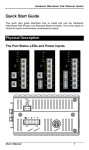
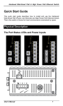
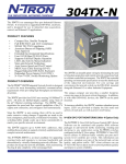
October, 2006
Express
Ethernet Switch:
LB9017A-R4
CUSTOMER
SUPPORT
INFORMATION
Order toll-free in the U.S. : Call 877-877-BBOX ( outside U.S. call 724-746-5500 )
Free technical support 24 hours a day, 7 days a week: Call 724-746-5500 or fax
724-746-0746
Mailing address: Black Box Corporation, 1000 Park Drive, Lawrence, PA 15055-1018
Web site: www.blackbox.com • E-mail: [email protected]
Express Ethernet Switch : LB9017A-R4
FCC Statement
The FCC (Federal Communications Commission) restricts
the amount of radio frequency emission and radiation coming
from computer equipment.
The equipment introduced in this manual has been tested
and found to comply with the limits for a Class A digital
device pursuant to Part 15 of the FCC rules. These limits are
designed to provide reasonable protection against harmful
interference when the equipment is operated in a commercial
environment.
This equipment generates, uses, and can radiate radio
frequency energy, and if not installed and used in
accordance with the instruction manual, may cause harmful
interference to radio communications.
Operation of this equipment in a residential area is likely to
cause harmful interference in which case the user is required
to correct the interference at his/her own expense.
Any changes or modifications not expressly approved by the
manufacture would void the user’s authority to operate the
equipment.
Trademarks
Product names mentioned in this manual may be trademarks
or registered trademarks of those products.
All trademarks or brand names mentioned are properties of
their respective companies.
2
Express Ethernet Switch : LB9017A-R4
Preface
This manual describes how to install and use the 16 Ports Smart
Ethernet Switch. The TX ports of the switch introduced here autonegotiates the presence of 10/100Mbps and full/half-duplex mode
and auto-MDIX. In addition, it allows an optional 100BaseFX
multi-mode or single-mode fiber module, enabling long distance
connection.
To get the most out of this manual, you should have an
understanding of networking concepts such as bridging, IEEE
802.3 10BaseT Ethernet, IEEE 802.3u 100BaseTX/FX Fast
Ethernet, and local area networks (LANs).
For more information about these topics, please refer to the
Appendices.
In this manual, you will find:
•
•
•
•
•
3
Introduction on the Switch
Product features
Illustrative LEDs functions
Installation instructions
Specifications
Express Ethernet Switch : LB9017A-R4
Table of Contents
FCC STATEMENT
2
TRADEMARKS
2
PREFACE
3
TABLE OF CONTENTS
4
PRODUCT OVERVIEW
6
FRONT VIEW .................................................................................... 6
PACKAGE CONTENTS ........................................................................ 6
PRODUCT FEATURES ........................................................................ 7
FRONT PANEL DISPLAY ..................................................................... 8
PHYSICAL PORTS.............................................................................. 9
Understanding Front Panel Design
INSTALLATION
9
10
SELECTING A SITE FOR THE EQUIPMENT ........................................... 10
INSTALLATION AND PLACEMENT INSTRUCTIONS ................................. 11
Mounted to 19-inch standard rack
Desktop or any flat surface
11
11
OPTIONAL FIBER MODULE INSTALLATION .......................................... 12
CONNECTING TO POWER ................................................................. 13
CONNECTING TO YOUR NETWORK ................................................... 13
Cabling
Network Segmentation
SWITCH CONFIGURATION
13
14
15
SETTING UP WEB-BASED BROWSER INTERFACE ............................... 15
LOGGING ON TO THE ETHERNET SWITCH .......................................... 15
Switch IP Address
ID
Password
15
16
16
MAIN MENU .................................................................................... 17
System Change
IP Configuration
Port
4
18
19
20
Express Ethernet Switch : LB9017A-R4
VLAN
Trunking
QoS Mode
QoS Priority
Load Default
Firmware Update
21
22
23
24
25
26
TECHNICAL SPECIFICATIONS
27
PHYSICAL SPECIFICATIONS
28
CONNECTOR PINOUTS
29
ORDERING INFORMATION
30
5
Express Ethernet Switch : LB9017A-R4
Product Overview
Front View
Figure 1: 16 Ports Smart Ethernet Switch
Package Contents
When you unpack the product package, you shall find these items
listed below.
3
3
3
The 16 Ports Switch
One AC power cord
User’s Manual
Please inspect the contents, and report any apparent damage or
missing items immediately to your authorized reseller.
6
Express Ethernet Switch : LB9017A-R4
Product Features
♦
PROVIDES
16
×
10/100MBPS
PORTS
USING
RJ-45
CONNECTORS
♦
AN OPTIONAL SINGLE-PORT FIBER MODULE ALLOWS:
- 100BASEFX MULTI-MODE FIBER WITH SC, ST, MT-RJ, VF-45 OR LC
CONNECTOR
♦
- 100BASEFX SINGLE-MODE FIBER WITH SC OR ST CONNECTOR
- 100BASEFX WDM SINGLE-MODE FIBER WITH SC CONNECTOR
AUTO-NEGOTIATION FOR SPEED AND DUPLEX MODE ON TX
PORTS
♦
♦
♦
♦
♦
♦
♦
AUTO-MDIX FOR ALL TX PORTS
4K MAC ADDRESSES, 1.5M BITS BUFFER MEMORY
STORE-AND-FORWARD MECHANISM
TRUE NON-BLOCKING ARCHITECTURE
FULL WIRE SPEED FORWARDING RATE
BROADCAST STORM FILTERING CONTROL
BACK-PRESSURE AND IEEE 802.3X COMPLIANT
FLOW
CONTROL
♦
♦
♦
♦
7
SYSTEM, IP CONFIGURATION, PORT, PORT-BASED VLAN,
TRUNKING, QOS MODE, AND QOS PRIORITY SETTINGS
THROUGH THE WEB-BASED BROWSER.
PRESS THE FRONT PANEL IP RESET PUSH BUTTON TO RESET
THE ETHERNET SWITCH BACK TO THE DEFAULT SYSTEM
AND IP ADDRESS SETTINGS. (THE PORT, VLAN,
TRUNKING, QOS MODE, AND QOS PRIORITY SETTINGS
WILL REMAIN THE SAME AS WHEN THEY WERE LAST SAVED).
FRONT PANEL PORT AND POWER STATUS LEDS
STANDARD 19” RACKMOUNT SIZE, ONE-UNIT IN HEIGHT
Express Ethernet Switch : LB9017A-R4
Front Panel Display
The LED indicators on the front panel provide you with instant
feedback on each port status, and help you monitor and
troubleshoot the switch.
Figure 2: Front Panel LEDs
Power
This LED comes on when the switch is properly connected to power and
turned on.
IP Reset Push Button
Press the Front panel IP Reset push button to reset the Ethernet Switch
back with the default User Login ID, User Login Password, IP Address,
Netmask, and Gateway settings.
Port Status
The RJ-45 ports are numbered from 1 to 16 on the 16-Port Switch.
The LEDs are located on the front panel of the switch, displaying status for
each respective port. Please refer to the table below for more information.
Consult the following table for details.
L
8
Before you use this table for troubleshooting, make sure the switch is
properly connected to power and turned on.
Express Ethernet Switch : LB9017A-R4
Physical Ports
The 16 Ports Switch has sixteen 10/100Mbps ports using RJ-45
connectors and provides one slot for the optional single-port fiber
module. The optional module allows fiber type (multi-mode,
single-mode, or WDM single-mode fiber) and connector (SC, ST,
MT-RJ, VF-45, or LC) at user’s discretion.
UNDERSTANDING FRONT PANEL DESIGN
Power LED
On
Power feeding in
Off
Power switched off
Improper connection
Port LED
Link/ACT
On
A valid network connection
Flashing Transmitting or receiving data
ACT stands for ACTIVITY
Off
Neither connection nor activity
Speed
100FX
Link
Port LED
ACT
9
On
A valid 100Mbps connection
Off
A valid 10Mbps connection
On
A valid network connection
Off
No connection
Flashing Transmitting or receiving data
ACT stands for ACTIVITY
Neither transmitting nor receiving
Off
data
Express Ethernet Switch : LB9017A-R4
Installation
Selecting a Site for the Equipment
As with any electric device, you should place the equipment where
it will not be subjected to extreme temperatures, humidity, or
electromagnetic interference. Specifically, the site you select
should meet the following requirements:
-
The ambient temperature should be between 32 and 113
degrees Fahrenheit (0 to 45 degrees Celsius).
-
The relative humidity should be less than 90 percent,
non-condensing.
-
Surrounding electrical devices should not exceed the
electromagnetic field (RFC) standards for IEC 801-3, Level 2
(3V/M) field strength.
-
Make sure that the equipment receives adequate ventilation.
Do not block the ventilation holes on each side of the switch or
on the rear of the equipment.
-
The power outlet should be within 6 feet (1.8 meters) of the
switch.
10
Express Ethernet Switch : LB9017A-R4
Installation and Placement Instructions
MOUNTED TO 19-INCH STANDARD RACK
Locate the accessories supplied in the product package. Use the
rackmount brackets and screws to install the switch into any EIA
19” standard rack.
Step 1:
Attach the brackets to each side of the chassis.
Step 2:
Apply the screws to each side and secure them tightly.
Step 3:
Carefully position the switch into the rack.
Step 4:
Align the brackets to the side holes on the rack and use rack
screws to secure the chassis with the rack.
Step 5:
Proceed to the “Connecting to Power” section.
DESKTOP OR ANY FLAT SURFACE
The switch can sit on desktop or any flat surface with adequate
space and ventilation. If you want to place it onto a shelf, make
sure the shelf can withstand the weight of the switch.
Step 1:
Simply put the switch on the desired place.
Step 2:
Ensure the switch receives good ventilation.
Step 3:
Proceed to the “Connecting to Power” section.
11
Express Ethernet Switch : LB9017A-R4
Optional Fiber Module Installation
Consult the following illustrations before installation.
Step 1:
L
Make sure the power is switched off. The module is not hotswappable.
It may cause electric shock or any possible damage to the switch if the
power is not switched off.
Step 2:
Remove the module from the static-free container.
Step 3:
Unscrew the cover plate of the expansion slot.
(The slot for single-port module is located at the right side of the
switch.)
Step 4:
Remove the plate.
(Keep it for future use if you decide to remove this module later.)
Step 5:
Carefully slide the module into the slot, following the internal
plastic guide rails.
Step 6:
Once it is fully slid in, snap in the module to make a proper
connection.
Step 7:
Fasten the module screws.
Step 8:
Finally, turn on the power.
Figure 3: Removal of cover plate
12
Fiber module being installed
Express Ethernet Switch : LB9017A-R4
Connecting to Power
Locate the supplied AC power cord.
Step 1: Connect
the AC power cord to the receptacle at the back of the
switch.
Step 2: Attach the plug into a standard AC outlet with a voltage range from
100~240VAC.
Step 3:
The power LED on the front panel will then illuminate.
Connecting to Your Network
CABLING
Step 1:
L
First, ensure the power of the switch (and end devices) is turned
off.
It may cause an electric shock or any possible harm to you if the power
is not switched off.
Step 2:
Prepare cable with corresponding connectors for each type of port
in use.
(Consult the table below for cabling requirements based on
connectors and speed considerations.)
Step 3:
Connect one end of the cable to the switch and the other end to a
desired device.
Step 4:
Once the connections between two end devices are made
successfully, turn on the power and the switch is operational.
13
Express Ethernet Switch : LB9017A-R4
NETWORK SEGMENTATION
The maximum segment distance between a node and a directly
connected switch port on a 100BaseFX network is 120km using
10/125 (or 9/125) µm single-mode fiber optic cable. It is capable of
a maximum span of 2km when 62.5/125 (or 50/125) µm multimode fiber optic cable is used.
Cable Specifications Table
Ethernet
Connector
Standards
10BaseT
100BaseTX
100BaseFX
Multi-mode
RJ-45
RJ-45
ST, SC,
MT-RJ, VF45, LC
Port
Speed
Half/Full
Duplex
Cable
10/20
Mbps
Cat. 3, 4 or 5
100/200
Mbps
Cat. 5
100/200
Mbps
62.5/125µm
multi-mode
fiber
Up to
2km
Max.
Distance
100m
UTP/STP
100m
UTP/STP
100BaseFX
Single-mode
SC
100/200
Mbps
10/125µm
single-mode
fiber
Up to
120km
100BaseFX
Single-mode
ST
100/200
Mbps
10/125µm
single-mode
fiber
Up to
20km
100BaseFX
WDM
Single-mode
SC
100/200
Mbps
10/125µm
single-mode
fiber
Up to
40km
14
Express Ethernet Switch : LB9017A-R4
Switch Configuration
Setting up Web-Based Browser Interface
The Ethernet Switch provides a browser interface that lets
you configure and manage the Ethernet Switch from a Web
browser (such as Microsoft Internet Explorer or Netscape
Navigator) remotely.
By connecting to any port of this Ethernet Switch, you can
access the Ethernet Switch’s web interface applications
directly in your web browser by entering the default IP
address of the Ethernet Switch (192.168.1.10). You can then
use your web browser to list and manage the Ethernet Switch
configuration parameters from one central location.
Logging on to The Ethernet Switch
SWITCH IP ADDRESS
In your web browser, specify the default IP address of the
Ethernet Switch (192.168.1.10).
15
Express Ethernet Switch : LB9017A-R4
ID
Enter the factory default User Login ID: admin.
PASSWORD
Enter the factory default password (no password, press
<Enter> directly).
Otherwise, enter a user-defined password if you follow the
instructions later and change the factory default password.
16
Express Ethernet Switch : LB9017A-R4
Main Menu
17
Express Ethernet Switch : LB9017A-R4
SYSTEM CHANGE
The System Change parameters can be displayed by
clicking the System Change selection in the left sub-menu.
z
z
z
18
Switch Name: Type a switch name for this Ethernet
Switch.
New Password: Enter a user-defined password and
change the factory default password.
Update: Click the Update button and apply the new
System settings.
Express Ethernet Switch : LB9017A-R4
IP CONFIGURATION
The IP Configuration parameters can be displayed by
clicking the IP Configuration selection in the left sub-menu.
z
z
IP Address, Netmask, Default Gateway: You can see
and change the IP Address, Netmask, and Default
Gateway of the Ethernet Switch.
Update: Click the Update button and apply the new IP
Configurations.
L
Please relogin the switch with the new IP
Configuration after you click the update button.
19
Express Ethernet Switch : LB9017A-R4
PORT
The Port parameters can be displayed by clicking the Port
selection in the left sub-menu.
z
z
z
z
z
z
20
Port No.: Choose Port No. 01 ~ 17.
Auto Nway: Choose Enable or Disable to enable or
disable Auto Nway of the ports.
Speed: Choose 100M or 10M speed for the ports.
Duplex: Choose Full or Half Duplex for the ports.
Pause: Choose Enable or Disable to enable or disable
Pause for the ports.
Backpressure: Choose Enable or Disable to enable or
disable Backpressure for the ports.
Express Ethernet Switch : LB9017A-R4
z
Update: Click the Update button and apply the new
settings of the ports.
VLAN
The VLAN parameters can be displayed by clicking the
VLAN selection in the left sub-menu.
z
z
z
z
z
21
Group No: Click and choose the VLAN Group No 01 ~
08.
Member Port: Click and choose the Member Port 01 ~
17 to be added into the VLAN Group No 01 ~ 08.
Comment: Type Comment for VLAN Group No 01 ~ 08.
Update: Click the Update button and apply the new
settings of the VLAN groups.
Load Default: Click the Load Default button and load
the default settings of the VLAN groups.
Express Ethernet Switch : LB9017A-R4
TRUNKING
The Trunking parameters can be displayed by clicking the
Trunking selection in the left sub-menu.
z
z
z
z
22
Trunk Hash Algorithm Selection: Click and choose Port
ID, SA, DA, or SA & DA Trunk Hash Algorithm.
Trunk0: Click and choose Port1 ~ Port4 to be added
into the Trunk0.
Trunk1: Click and choose Port5 ~ Port8 to be added
into the Trunk1.
Update: Click the Update button and apply the new
settings of the Trunking Groups.
Express Ethernet Switch : LB9017A-R4
QOS MODE
The QoS Mode parameters can be displayed by clicking the
QoS Mode selection in the left sub-menu.
z
Click and choose First-In-First-Service, All-Highbefore-Low, or Weight-Round-Robin Priority Mode.
L The Priority Mode will be treated as “8” when both
z
23
Low weight and High weight of Weight-RoundRobin are set to “0”.
Update: Click the Update button and apply the new
settings of the QoS Mode.
Express Ethernet Switch : LB9017A-R4
QOS PRIORITY
The QoS Priority parameters can be displayed by clicking
the QoS Priority selection in the left sub-menu.
z
z
24
Click and choose Port Base, VLAN Tag, and/or IP / DS
for Port No 1 ~ 17.
Update: Click the Update button and apply the new
settings of the QoS Priority.
Express Ethernet Switch : LB9017A-R4
LOAD DEFAULT
The Load Default parameters can be displayed by clicking
the Load Default selection in the left sub-menu.
z
Click the Load button to load the default settings.
L Once the Load button is selected, all last saved
Port, VLAN, Trunking, QoS Mode and QoS Priority
settings will be reverted back to the default settings.
25
Express Ethernet Switch : LB9017A-R4
FIRMWARE UPDATE
The Firmware Update parameters can be displayed by
clicking the Firmware Update selection in the left sub-menu.
z
26
Click the Firmware Update button to update firmware
to the switch. The TFTP protocol is used to upload
firmware to the switch. You should install the TFTP &
DHCP server on your PC (Web management station)
before updating the firmware.
Express Ethernet Switch : LB9017A-R4
Technical Specifications
16 Ports Web-based Smart Ethernet Switch
Applicable
Standards
IEEE 802.3 10BaseT
Fixed Ports
IEEE 802.3u 100BaseTX/FX
Sixteen ports for the 16-Port Switch
Optional 1-port
100BaseFX multi-mode or single-mode module
Module Type
Speed
100BaseTX/FX:
200Mbps for full-duplex; 100Mbps for half-duplex
Switching
Method
Performance
10BaseT:
20Mbps for full-duplex; 10Mbps for half-duplex
Store-and-Forward
148,810pps forwarding rate per port for 100Mbps
14,881pps forwarding rate per port for 10Mbps
Chassis
LED Indicators
Power
TX port:
Link/ACT; SPEED (2 LEDs)
FX port:
Link/ACT (1 LED)
27
Express Ethernet Switch : LB9017A-R4
Physical Specifications
16 Ports Web-based Smart Ethernet Switch
Dimensions
17.3 x 8.2 x 1.74 in. (W440 × D207 × H44 mm)
19” rack mount size, 1U high
Weight
Approximately 6.2 pounds (2.8kg)
Power Input
100 ~ 240 VAC, 50~60 Hz
Power
Dissipation
7.4W Maximum
Operating
Temperature
0° ~ 45°C (32° ~ 113°F)
Storage
Temperature
-10° ~ 70°C (14° ~ 158°F)
Humidity
10 ~ 90%, non-condensing
Emissions
FCC part 15 Class A, CE Mark
28
Express Ethernet Switch : LB9017A-R4
Connector Pinouts
Pin arrangement of RJ-45 connectors:
Figure 4: RJ-45 Connector and Cable Pins
The following table lists the pinout of 10/100BaseT/TX ports.
Connector Pin-Out
Pin
1
2
3
4
5
6
7
8
29
Regular Ports
Input Receive Data +
Input Receive Data Output Transmit Data +
NC
NC
Output Transmit Data NC
NC
Uplink port
Output Transmit Data +
Output Transmit Data Input Receive Data +
NC
NC
Input Receive Data NC
NC
Express Ethernet Switch : LB9017A-R4
Ordering Information
16 Fixed Ports
Cable
Connector
100BaseTX:
Cat. 5 or better
UTP/STP
Single-Port Module
Distance
Speed
100m
100BaseFX
Cable (/125µm)
Connector
MMF
100BaseFX
SC
MMF
100BaseFX
ST
MMF
100BaseFX
MT-RJ
MMF
100BaseFX
VF-45
MMF
100BaseFX
LC
SMF
100BaseFX
SC
SMF
100BaseFX
ST
WDM SMF
RJ-45
OR
10BaseT:
Cat. 3, 4, 5 or
better UTP/STP
RJ-45
Distance
3
2km
(50µm or 62.5µm)
2km
(50µm or 62.5µm)
2km
(50µm or 62.5µm)
2km
(50µm or 62.5µm)
2km
(50µm or 62.5µm)
(9µm or 10µm)
(9µm or 10µm)
(9µm or 10µm)
Up to
120km
Up to
20km
Up to
40km
SC
L
i.
ii.
30
The maximum node-to-node network distance is in full-duplex operation.
MMF denotes Multi-Mode Fiber. SMF denotes Single-Mode Fiber.