1
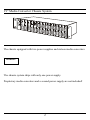
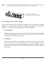
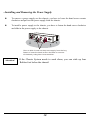
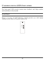
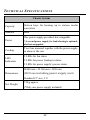
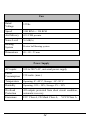
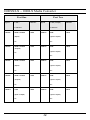
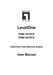
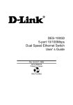
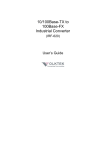
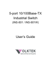
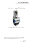
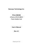
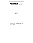
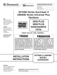
Media Converter Chassis System User’s Guide FCC Warning This equipment has been tested and found to comply with the regulations for a Class A digital device, pursuant to Part 15 of the FCC Rules. These limits are designed to provide reasonable protection against harmful interference when the equipment is operated in a commercial environment. This equipment generates, uses, and can radiate radio frequency energy and, if not installed and used in accordance with this user’s guide, may cause harmful interference to radio communications. Operation of this equipment in a residential area is likely to cause harmful interference, in which case the user will be required to correct the interference at his or her own expense. CE Mark Warning This is a Class A product. In a domestic environment, this product may cause radio interference, in which case the user may be required to take adequate measures. VCCI Warning This is a product of VCCI Class A Compliance. P/N: 2907MCR11615000 TABLE OF C ONTENTS PREFACE.....................................................................................................1 19” MEDIA CONVERTER CHASSIS SYSTEM .................................................. 2 PRODUCT FEATURES..............................................................................3 PRODUCT FEATURES .................................................................................... 3 UNPACKING AND INSTALLATION ......................................................5 UNPACKING ................................................................................................. 5 INSTALLATION ............................................................................................. 5 DECIDING HOW TO INSTALL THE SYSTEM.................................................... 6 . Mounted to 19-inch standard rack .................................................... 6 . Installing Media Converter ............................................................... 7 . Connecting to Power (Power Supply) ............................................... 8 . Installing and Removing the Power Supply..................................... 10 UNDERSTANDING LED INDICATORS ...............................................11 FRONT PANEL ............................................................................................ 11 POWER AND FAN LED ............................................................................... 12 TECHNICAL SPECIFICATIONS...........................................................13 ORDERING INFORMATION .................................................................15 100TX ~ 100FX MEDIA CONVERTER ........................................................ 15 10/100TX ~ 100FX MEDIA CONVERTER ................................................... 16 1000T ~ 1000SX/LX MEDIA CONVERTER ................................................. 18 100FX ~ 100FX MEDIA CONVERTER ........................................................ 19 1000SX/LX ~ 1000LX MEDIA CONVERTER .............................................. 20 POWER SUPPLY .......................................................................................... 21 CPU MODULE............................................................................................ 21 i P REFACE This manual describes how to install and use the 19” Media Converter Chassis System. The system introduced here is capable of housing up to sixteen media converters, each of which offers one channel media conversion solution: 100BASE-TX 10/100BASE-TX 100BASE-FX 1000BASE-T 1000BASE-SX ↔ 100BASE-FX ↔ 100BASE-FX ↔ 100BASE-FX (multi-mode ↔ single-mode) ↔ 1000BASE-SX/LX ↔ 1000BASE-LX (multi-mode ↔ single-mode) In this manual, you will find: Introduction on the Chassis System Product features Illustrative LEDs functions Installation instructions Specifications Ordering Information Attention! The chassis Shown in the figures of this manual is fitted with redundant power supplies. Proprietary media converters and a second power supply shall be ordered separately! 1 19” Media Converter Chassis System The chassis equipped with two power supplies and sixteen media converters. Attention! The chassis system ships with only one power supply. Proprietary media converters and a second power supply are not included! 2 P RODUCT F EATURES This chapter describes the features of the Media Converter Chassis System. Product Features ¾ Plug-and-Play ¾ House up to Sixteen media converters ¾ Front panel LEDs for bay and fan power status ¾ Standard 19” rackmountable size, 2U ¾ Non-stop operation & minimal downtime ¾ The following items are designed to be hot swappable to allow easy and quick replacement: - Media converters - Redundant Power supplies ¾ Provides cooling fans at the back together with power supply ¾ Power redundancy & power isolation ¾ One high quality internal power supply provided, and a second power supply option for load-sharing purpose. ¾ Load sharing mechanism: If one power supply should fail, the redundant power supply is capable of taking over immediately ¾ The Media Converter’s power isolation ensures each bay is electrically isolated from each other 3 U NPACKING AND I NSTALLATION This chapter provides unpacking and installation information for the Switch. To avoid causing any damage to the Switch, we recommend that you read this chapter carefully before starting installation. Unpacking When unpacking the product package, you shall find these items listed below. ¾ 19” Media Converter Chassis System ¾ One power supply installed on the chassis ¾ One AC power cord ¾ User’s Manual ¾ Accessories: rackmount screws (8 pcs) & rackmount ears (2 pcs) rubber foot (4 pcs) If any item is found missing or damaged, please contact your local reseller for replacement. Installation The site where you place the chassis system may greatly affect its performance. When installing, take the following into your consideration: As with any electric device, you should place the equipment where it will not be subjected to extreme temperatures, humidity, or electromagnetic interference. Specifically, the site you select should meet the following requirements: 5 The ambient temperature should be between 32 and 104 degrees Fahrenheit (0 to 40 degrees Celsius). The relative humidity should be less than 90 percent, non-condensing. Surrounding electrical devices should not exceed the electromagnetic field (RFC) standards for IEC 801-3, Level 2 (3V/M) field strength. Make sure that the equipment receives adequate ventilation at the rear. Do not block the fan exhaust holes on the rear of the chassis. The power outlet should be within 1.8 meters of the chassis. Deciding How to Install the System We strongly suggest that you install the chassis first, as this is more convenient for you to install media converters into the chassis with ease. The accessories supplied in the product package includes: rackmount screws(8 pcs) and rackmount brackets(2 pcs). This well-built chassis can be installed in the following ways: .Mounted to 19-inch standard rack Use the rackmount brackets and screws to install the chassis into any EIA 19” standard rack. Step 1: Attach the brackets to each side of the chassis. Apply four screws to each side and secure them tightly. 6 Step 2: Carefully position the chassis into the rack. Align the brackets to the side holes on the rack and use rack screws to secure the chassis with the rack. Step 3: Proceed to the “Connecting to Power” section. .Installing Media Converter The chassis is equipped with sixteen media converter carriers, each of which is fitted into bays of the chassis. Step 1: To install a media converter module onto the chassis, you have to unscrew the bay cover from the desired bay first. Step 2: Unscrew the hand screw counter clockwise by using hand or screwdriver and pull out the media converter out the carrier as shown below. Unscrew the hand screw counter clockwise by using hand or screwdriver and pull the media converter module out on the carrier 7 Step 3: Carefully slide in the module and fasten the hand screw clockwise by using hand or screwdriver until it is fully and firmly fitted into the slot of the chassis. Insert the media converter module into an available slot and fasten the hand screw clockwise by using hand or screwdriver. .Connecting to Power (Power Supply) The chassis ships with only one power supply, and a second power supply option is at your discretion. When the chassis is equipped with two power supplies, you can have the following advanced performance. ♦ Hot Swappable – The design of the power system is based on an idea of providing maximum flexibility and redundancy. In this way, you may remove any of the two power supplies without turning off the system. ♦ Redundancy – During operation, both power supplies are switched on and share the current load. In case that one of them should fail, the other will instantaneously take 100% of the load without any loss. Similarly, if one power supply is removed from servicing, it can be switched off and removed while the chassis continues functioning. 8 ♦ Protection System – The power of each converter bay comes from the two shared power supplies. Each bay is isolated from each other under a certain protection mechanism, so that it is free from any problem that might occur to the power supplies or faulty converter bay. This is the best solution to protect your investment in media converters. Attention! There is an optional solution for the backup power, -48 volt DC to DC Power Supply. The chassis system is equipped with one power supply and allows one additional power supply for redundancy. For reliable operation, we suggest that you run the chassis system with two power supplies are in place. Step 1: Connect the supplied AC power cord to the back of the chassis. Step 2: Attach the plug into a standard AC outlet with a voltage range from 100~240Vac. Step 3: Turn on the chassis system by flipping the switch beside the receptacle to ON position. The LED on the front panel of power supply will come on then. 9 .Installing and Removing the Power Supply z To remove a power supply out the chassis, you have to loose the hand screw counter clockwise and pull out the power supply from the chassis. z To install a power supply to the chassis, you have to fasten the hand screw clockwise and slide in the power supply to the chassis. You c a n slid e in a nd out the p ower sup p ly from the b ay, fa sten or loose the ha nd sc rew c loc kwise or c ounter c loc kwise b y using hand or sc re wdriver. Attention! If the Chassis System needs to work alone, you can stick up four Rubber foot below the chassis! 10 U NDERSTANDING LED I NDICATORS The front panel LEDs provide instant status feedback, and, helps monitor and troubleshoot when needed. Front Panel There is an array of LED indicators, which provides you with instant feedback on the status of the power and the fan. 1 POWER ON POWER FAIL FAN FAIL 11 2 Power and Fan LED 1/2 Indicates which the power (fan) is working, depends on where the power supply was installed at the rear. Power LED On (Green) Power supply feed in Off No power supply feeding On (Amber) Faulty power supply Off Power supply works normally Power Fail LED Fan Fail LED On (Amber) Off Faulty Fan Fan works normally 12 T ECHNICAL S PECIFICATIONS Chassis System Capacity Sixteen bays for housing up to sixteen media converters Material Steel One power supply provided, hot-swappable Power Cooling *A second power supply for load-sharing is optional, also hot-swappable Two fans mounted together with the power supply or alone at the rear 2 LEDs for fan status LED Indicators 2 LEDs for power feeding in status 2 LEDs for power supply’s power status W440 mm × D 360 mm × H88 mm Dimensions (D395 mm including power supply unit) Standard 19” size, 2 U Net Weight 7.0kg approx. (*Only one power supply included) 13 Fan Rated Voltage 12Vdc Speed 3200 RPM +/- 250 RPM Air Delivery 42.5 CFM per min. Noise Level 36.5dB(A) Bearing System Precise ball bearing system Dimensions 80 × 80 × 25 mm Power Supply AC inputs: 100 to 240 VAC, universal power supply Power Consumption: 150 watts. (max.) Temperature Operating: 0°~40° C, Storage: -10°~50° C Humidity Operating: 10% ~ 90%, Storage: 5% ~ 90% Overload Protection All outputs protected from short circuit condition, automatic recovery Emissions: FCC Class A, CE Mark Class A, 14 VCCI Class A O RDERING I NFORMATION 100TX ~ 100FX Media Converter Port One Speed Cable / Port Two Distance Speed Cable (/125µm) Connector 100TX 2-pairs Cat. 5 Distance Connector 100m 100FX RJ-45 MMF 2km (50µm or 62.5µm) SC 100TX 2-pairs Cat. 5 100m 100FX RJ-45 MMF 2km (50µm or 62.5µm) ST 100TX 2-pairs Cat. 5 100m 100FX RJ-45 MMF 2km (50µm or 62.5µm) MT-RJ 100TX 2-pairs Cat. 5 100m 100FX RJ-45 MMF 2km (50µm or 62.5µm) LC 100TX 2-pairs Cat. 5 100m 100FX RJ-45 SMF (9µm or 10µm) SC 15 15km 100TX 2-pairs Cat. 5 100m 100FX RJ-45 SMF 30km (9µm or 10µm) SC 100TX 2-pairs Cat. 5 100m 100FX RJ-45 SMF 40km (9µm or 10µm) SC 100TX 2-pairs Cat. 5 100m 100FX RJ-45 SMF 60km (9µm or 10µm) SC 10/100TX ~ 100FX Media Converter Port One Speed Cable / Port Two Distance Speed Cable (/125µm) Connector 10/100 TX 2-pairs Cat. 5 Distance Connector 100m 100FX RJ-45 MMF 2km (50µm or 62.5µm) SC 10/100 TX 2-pairs Cat. 5 100m 100FX RJ-45 MMF (50µm or 62.5µm) ST 16 2km 10/100 TX 2-pairs Cat. 5 100m 100FX RJ-45 MMF 2km (50µm or 62.5µm) MT-RJ 10/100 TX 2-pairs Cat. 5 100m 100FX RJ-45 MMF 2km (50µm or 62.5µm) LC 10/100 TX 2-pairs Cat. 5 100m 100FX RJ-45 SMF 15km (9µm or 10µm) SC 10/100 TX 2-pairs Cat. 5 100m 100FX RJ-45 SMF 30km (9µm or 10µm) SC 10/100 TX 2-pairs Cat. 5 100m 100FX RJ-45 SMF 40km (9µm or 10µm) SC 10/100 TX 2-pairs Cat. 5 100m 100FX RJ-45 SMF (9µm or 10µm) SC 17 60km 1000T ~ 1000SX/LX Media Converter Port One Speed Cable / Port Two Distance Speed Cable (/125µm) Connector 1000T 4-pairs Cat. 5 Distance Connector 100m 1000SX RJ-45 MMF of 850nm 550m (50µm) SC 1000T 4-pairs Cat. 5 100m 1000SX RJ-45 MMF of 850nm 220m (62.5µm) SC 1000T 4-pairs Cat. 5 100m 1000LX RJ-45 SMF 10km (9µm or 10µm) SC 1000T 4-pairs Cat. 5 100m 1000LX RJ-45 SMF (9µm or 10µm) SC 18 20km 100FX ~ 100FX Media Converter Port One Speed Cable / Port Two Distance Speed Connector 100FX 100FX 100FX 100FX MMF Cable (/125µm) Connector 2km 100FX SMF (50µm or 62.5µm) (9µm or 10µm) SC SC MMF 2km 100FX SMF (50µm or 62.5µm) (9µm or 10µm) SC SC MMF 2km 100FX SMF (50µm or 62.5µm) (9µm or 10µm) SC SC MMF Distance 2km 100FX SMF (50µm or 62.5µm) (9µm or 10µm) SC SC 19 15km 40km 30km 60km 1000SX/LX ~ 1000LX Media Converter Port One Speed Cable / Port Two Distance Speed Connector 1000SX 1000SX MMF of 850nm Cable (/125µm) Connector 550m 1000LX SMF (50µm) (9µm or 10µm) SC SC MMF of 850nm (62.5µm) Distance 220m 1000LX SMF 10km 10km (9µm or 10µm) SC SC 1000SX 1000SX 1000LX MMF of 850nm 550m 1000LX SMF (50µm) (9µm or 10µm) SC SC MMF of 850nm 220m 1000LX SMF (62.5µm) (9µm or 10µm) SC SC SMF 20km 1000LX SMF (9µm or 10µm) (9µm or 10µm) SC SC 20 20km 20km 20km Power Supply Power Type 150 Watt AC to DC Power Supply -48 Volt DC to DC Power Supply CPU Module Manageable for the Chassis System using console port. 21