1
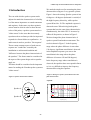
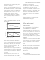
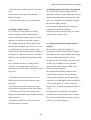
A White Paper
Of
The Installation Series Loudspeakers
YAMAHA CORPORATION
PA·DMI Division,
Advanced System Development Center
A White Paper Of The Installation Series Loudspeakers
We made the simple test for measuring the phase
1 Introduction
characteristics using two 2-way speaker systems.
The ease with which a speaker system can be
adjusted to match the characteristics of a facility
is of the utmost importance to sound contractors
and engineers. In the same way that a painter's
canvas must be white in order to show the true
colors of his paints, a speaker system must be a
"white canvas" in the sense that it accurately
reproduces the waveforms provided as input and
responds in a linear fashion to equalization − in
audio terms it needs to provide a "flat response".
The two most common causes of such uneven
response are "comb filter" caused by the
Figure 1 shows the setting. Speaker system A has
60 degrees x 40 degrees (horizontal x vertical) of
the high frequency directivity, while speaker
system B has 90 x 50. The amplitude response is
almost the same. When driving both speaker
systems that have the same phase characteristics
simultaneously, the relative S.P.L. increases by
6dB at all frequencies, as shown in Figure 2.
We then changed the phase characteristics of
speaker system B and made measurement. The
result is shown in Figure 3. In the frequency
range where the phase difference is more than
120 degrees, significant cancellation is observed
installation or architectural condition and
"difference between the phase characteristics of
the speakers". The former must be considered in
the aspect of the system design such as speaker
angle, etc.
The latter should be considered as the important
matter for making the Yamaha speaker system as
"white canvas".
in the amplitude response (you can see the
cancellation in the range where the phase
difference is between 120 and 240 degrees).
In the frequency range where cancellation is
observed, the equalizer does not respond in linear
so it is very difficult to improve the frequency
characteristics using the equalizer.
<Figure 2: Driving two speaker systems that have the same
phase characteristics>
<Figure 1: Speaker measurement condition>
Amplitude
Speaker A
Relative S.P.L. [dB]
10dB
6ft
6ft
Speaker A
Speaker B
A+B
Speaker B
100
1000
Frequency [Hz]
-2-
10000
A White Paper Of The Installation Series Loudspeakers
Yamaha thought that "even if different speaker
Phase
models are used in a system, we should offer a
180
150
"white canvas" and paid attention to the phase
120
Phase [Degree]
90
characteristics, aiming for the unification of the
60
30
0
phase characteristics through the series. As for
-30
-60
Speaker A
Speaker B
A+B
-90
-120
-150
sound quality, we aimed for both the clearness of
speech (PA) and the high-fidelity sound
-180
100
1000
Frequency [Hz]
10000
reinforcement of vocals/musical instruments,
while the unification of the tone color (Family
<Figure 3: Driving two speaker systems that have different
phase characteristics>
Sound Concept) of all products in the series was
the basic concept.
Also , we made a great effort to reproduce the
Amplitude
natural dimensions of the sound image.
Relative S.P.L. [dB]
10dB
In other words , the size of image must be an
accurate representation of the source , particularly
with regard to speech. In short, the design
Speaker A
Speaker B
A+B
100
concept of the "Installation" series is to realize the
1000
10000
concepts for the phase characteristics and tone
color.
Frequency [Hz]
Phase
The following explains the details of our concept,
180
150
as well as how to realize the concept.
120
Phase [Degree]
90
60
30
0
-30
-60
-90
-120
-150
Speaker A
Speaker B
A+B
-180
100
1000
Frequency [Hz]
10000
2 Consideration of speaker
phase characteristics
This problem happens not only between the same
In a design of “the installation series”, we
speaker models but also between the different
investigated the influences of phase
speaker models.
characteristics of speakers into their responses at
For example, in a live concert, it is common to
receiving points at first.
make speaker arrays using the multiple same
speaker systems. However, in a facility, it is
common to use different speaker models together.
-3-
A White Paper Of The Installation Series Loudspeakers
1) About phase characteristics between
drivers
<Figure 4: Influence of the phase difference to the
amplitude response>
Even a single speaker system may have the outLF drivers of a 2-way speaker system).
Figure 4 shows the phase response of a 2-way
Relative S.P.L. [dB]
of-phase problem (for example, between HF and
10dB
Low
High
Low+High
speaker system. The cutoff frequency is 1.5 kHz
100
1000
for both the HPF (18 dB/oct, BW) and LPF (18
10000
Frequency [Hz]
dB/oct, BW).
180
Let's focus on 1.5 kHz frequency now.
150
120
see that 1.5 kHz frequency sound is reproduced
both by the HF and LF drivers. From the graph of
90
Phase [Degree]
From the graph of the amplitude response, you can
60
30
0
-30
-60
-90
Low
High
Low+High
-120
the phase response, you can see that the phase
-150
-180
100
difference between HF and LF is 180 degrees.
1000
Frequency [Hz]
10000
Both signal levels are equal so both cancel each
other and in result, the dip is created in the
<Figure 5: Response of a speaker system that has in-phase
amplitude characteristics. Also in the overall
units>
phase response graph, you can see that the phase
result, the speaker system has a bad phase
characteristics around the crossover point.
Relative S.P.L. [dB]
suddenly changes between 1 kHz and 2 kHz. In
10dB
Low
High
Low+High
100
Figure 5 shows the phase response of the same 2-
1000
10000
Frequency [Hz]
way speaker system as Figure 4, however, the
speaker system is adjusted for reducing the phase
180
150
120
difference in the range between 1 kHz and 2 kHz
characteristics is constant over the whole range,
Phase [Degree]
within 90 degrees. The slope of the phase
90
60
30
0
-30
-60
-90
so the bad influence to the amplitude
-120
characteristics is minimized.
-180
-150
100
The "installation" series has smooth phase
response that has the constant slope over the
whole range.
-4-
Low
High
Low+High
1000
Frequency [Hz]
10000
A White Paper Of The Installation Series Loudspeakers
the phase difference is within 120 degrees at 1
2) Discussion on phase response when
multiple speaker systems are used
kHz or less frequency. It is thought that, under
this amount of phase difference, interference
For installation to a hall, theater, church, etc.,
can be ignored. Therefore, in this condition, it
multiple speakers may be stacked in arrays.
is very important to match the phase
In such conditions, there may be a problem in
characteristics of two speakers in order to get
the overlapped area where more than one
the amplitude characteristics with no dip (as
speaker covers. That is, as described in 2-1)
with the discussion of phase characteristics
above, there may be a dip in the amplitude
between drivers described earlier).
response.
(Note that, practically, because the directivity
This is because of the phase difference that is
of a speaker changes depending on frequency,
caused by the distance difference between the
you have to consider frequency, directivity and
speaker position and the listening position.
distance.)
Therefore, from the view point of the system
<Figure 6: Considering the characteristics in the
overlapped area>
design, it is very important to reduce the
overlapped area but actually it is very difficult
L
to perfectly eliminate it. Under the condition
where two speakers are used as shown in
Figure 6, Table 1 shows the relation between
the "distance difference" and "out-of-phase
2ft
θ
frequency". The distance difference shows the
Overlap Area
dl
difference between the distances from these
speakers to the testing point. The frequency
shows the point where the phase difference
caused by the distance difference is 90 degrees.
<Table 1: The relation between the distance difference and
The parameter θ is the angle with the center
out-of-phase frequency in the overlapped area>
axis.
θ
5
Table 1 indicates the following.
When the overlapped area is within 10 degrees,
10
the phase difference caused by the distance
15
difference in the overlapped area is within 90
20
degrees at 1 kHz or less frequency, regardless
L=6 m
0,174 /
3 3252 Hz
0,347 /
1.627 Hz
0,517 /
1.087 Hz
0,683 /
817 Hz
L=12 m
0,174 /
3.249 Hz
0,347 /
1.626 Hz
0,517 /
1.086 Hz
0,684 /
816 Hz
Phase difference = 90 degrees
of the distance from the sound source.
When the overlapped area is within 20 degrees,
-5-
L=24 m
0,174 /
3.248 Hz
0,347 /
1.626 Hz
0,518 /
1.085 Hz
0,684 /
816 Hz
A White Paper Of The Installation Series Loudspeakers
affected by the dip caused by the interference
θ
5
10
15
20
L=6 m
0,087 /
4.336 Hz
0,174 /
2.170 Hz
0,261 /
1.449 Hz
0,347 /
1.089 Hz
L=12 m
0,087 /
4.332 Hz
0,174 /
2.168 Hz
0,261 /
1.448 Hz
0,347 /
1.088 Hz
L=24 m
0,087 /
4.331 Hz
0,174 /
2.167 Hz
0,261 /
1.447 Hz
0,347 /
1.088 Hz
expands, as well as the dip frequency lowers.
When the phase difference is 90 degrees, if θ is
15 degrees or less, the level difference at 1kHz or
below is within 3 dB.
When the phase difference is 150 degrees, even
if θ is 0 degrees or less, the level difference at
1kHz or below is more than 6 dB. These results
Phase difference = 120 degrees
show that, when using more than one speaker,
To confirm the validity of our consideration,
we made the following test.
Using the Yamaha SREV1, we created the
it is very important to match the phase
characteristics of the speakers in order to get
the same response at any position in the room.
phase differences of 90, 120 and 150 degrees at
2 kHz by simulating the impulse response that
<Figure 7: Test condition>
has a different inclination of phase
characteristics in the frequency range.
60ft
Then we compared the frequency response at
θ
the testing point.
0 degree
Boundary Mic.
5 degree
10 degree
Figure 7 shows the test condition while Figure
AMP
YAMAHA: SREV1
Phase
8 shows the result.
The testing point is fully apart from the wall.
PC
Smaart
Live
We use a boundary microphone in order to
avoid the effect of the reflected sound from the
wall and floor.
All the results are standardized by the result
under the condition where θ=0 and no phase
<Figure 8: Characteristics in the overlapped area>
Phase 0 degree
difference.
5
degree of their side taper is 15 degree.
0
When there is no phase difference, if θ is 15
degrees or less, the level difference at 2 kHz or
below is within 3 dB. If θ is 25 degrees or less,
the level difference at 1 kHz or below is within
Relative S.P.L. [dB]
Both speakers have a 60x40 directivity and the
-5
-10
deg
deg
deg
deg
deg
deg
-15
-20
5
10
15
20
25
30
-25
3 dB.
100
As the phase difference increases, the area
-6-
1000
Frequency [Hz]
10000
A White Paper Of The Installation Series Loudspeakers
For designing the "Installation" series speakers,
Phase 90 degrees
Yamaha focused on this point and considered it
5
very important to match the phase
Relative S.P.L. [dB]
0
characteristics not only between the same
-5
speaker models but also between different
-10
deg
deg
deg
deg
deg
deg
deg
-15
-20
0
5
10
15
20
25
30
models.
-25
100
1000
10000
Frequency [Hz]
<Figure 9: Variations of speaker combinations>
Phase 120 degrees
<Same enclosures, different directivities>
5
Relative S.P.L. [dB]
0
-5
-10
deg 0
deg 5
deg 10
deg 15
deg 20
deg 25
deg 30
-15
-20
-25
100
1000
10000
Frequency [Hz]
<Same enclosures, different drive modes>
Phase 150 degrees
5
Relative S.P.L. [dB]
0
-5
-10
deg 0
deg 5
deg 10
deg 15
deg 20
deg 25
deg 30
-15
-20
<Same enclosures, different power models>
-25
100
1000
10000
Frequency [Hz]
In actual speaker installation to a theater, etc., it
is common to use several speaker models with
different directivity according to the necessary
cover range.
Also, there may be several speaker handling
power combinations (see Figure 9).
-7-
A White Paper Of The Installation Series Loudspeakers
- Same phase characteristics between passive
<Combination of different enclosure-size models>
and bi-amp models with the same enclosure.
- Same phase characteristics between highpower and middle-power (will be available in
the autumn of 2005) models with the same
enclosure.
- Same phase characteristics between different
enclosure models.
- The phase difference between speakers at 2
kHz must be within 90 degrees.
(2) Using the minimum phase change
type
There are two methods of controlling the phase
characteristics of multi-way speaker systems.
3. Design concept
According to the experiment mentioned above,
we recognized a phase control as the one of the
most important factor. Then, we especially
focused on the balance of a phase and tone
control, and aimed to realize both the "In Phase
Concept" and "family sound concept". The
followings are details of each concept.
A. Minimum phase change type
This method aims for minimizing the phase
change between 20 Hz and 20 kHz. It realizes
the smoothly changed phase characteristics
within one lap (180 degrees to -180 degrees).
It is likely to have the level-down problem of
the amplitude characteristics in the frequency
range where low-frequency and high-frequency
drivers are crossed over.
1) Phase control
B. Same phase slope type
This method aims for the smooth phase change
(1) In Phase concept
From the result described above, the phase
characteristics of all speakers in this series must
be the same.
over the whole frequency range. It does not aim
for minimizing the phase change.
By adding a delay to the low-frequency driver to
match the phase slope of the low-frequency
- Same phase characteristics between the same
enclosure models that have different
driver to the slope of the high-frequency driver,
the phase characteristics of two drivers are
smoothly joined.
directivities
With this method, at the boundary of the phase
-8-
A White Paper Of The Installation Series Loudspeakers
characteristics of the two drivers, the phase
network circuit sounded better.
difference is 360 degrees.
Also, there was a fear that each model may
However, from the view point of boost/cut of
have the different delay time of the low-
the amplitude characteristics, it can be regarded
frequency driver if all the "Installation" series
as the same phase, which can avoid the level-
speakers were adjusted by applying the "same
down problem in the crossover range. This
phase slope" method. This might cause the
method is simpler and easier than the
problem when using more than one speaker
"minimum phase change type", though the
together.
phase significantly changes over the whole
By these reasons above, we decided to use
range.
"minimum phase change type".
<Figure 10: "Minimum phase change type" and "same
phase slope type"
180
Phase (degree)
2) Tone quality control
(1) Target sound
-180
We set the main targets of the "installation"
Frequency
series to halls, theaters and churches.
Minimum phase change type
Such facilities might have conferences, music
180
Phase (degree)
concerts, musicals, lectures, etc. Therefore, for
the SR system, offering clear and good sound
was the minimum requirement, as well as
providing enough audible level at any position
-180
Frequency
in the area.
Same phase slope type
Furthermore, it was also required to offer highBefore starting designing the "Installation"
series, we made prototypes of both "minimum
phase change" and "same phase slope" types,
and gave a listening/comparison test. The
fidelity sound for vocal and music instruments,
as well as for playback of music or ambient
sound.
Therefore, for tone quality of the "Installation"
following shows the result.
When testing with a bi-amp speaker using the
DSP, though there was a different nuance in the
crossover range, it was hard to say which one
was better.
series products, we aimed for realizing the
following, in addition to the flat amplitude
characteristics.
Speech intelligibility
When testing with a passive speaker, the
minimum phase change type with a simple
-9-
- Well-balanced and well-separated tone for music
A White Paper Of The Installation Series Loudspeakers
- Non coloration sound regardless of the total
(3) Minimizing the electronic compensation
level
The equalizing operation compensates the
- Same timbre at any position within the
amplitude response; on the other hand it causes
directivity range
deterioration of the phase characteristics. The
- Adequate audio image size of each source
more you compensate the amplitude response,
the more the phase changes.
So we aimed for minimizing the electronic
(2) Family Sound Concept
compensation using the equalizer.
For a facility in a hall, theater or church,
Especially for the crossover range, we aimed
auxiliary speakers such as under-balcony
not to use the equalizer at all.
speaker and frontfill speaker may be used for
audience, in addition to the main speakers.
The sounds generated by these speakers are
(4) Cooperation with an outside speaker
mixed in the room/hall space. However, it was
designer
very difficult to get the same timbre at any
We decided to design the speakers in
position in the room/hall because the timbre of
cooperation with an outside speaker designer.
each speaker is different if the size or model is
The leader of the Yamaha speaker developing
different (even though the manufacturer is the
team was Akira Nakamura. He was the
same).
developer of the "NS1000M" long-seller hi-fi
Now, Yamaha introduces "Family Sound
speaker, the "NS10M" de facto standard
Concept". According to this concept, all
speaker in the studio and the "MSP series"
speaker models in the same series has the same
powered monitor speakers.
tone color.
We appointed Mr. Michael Adams as the
outside speaker designer. He is not only a
- Unification of the tone color between the
veteran speaker designer but also has a long
different directivity models using the same
experience as an SR engineer and currently he
enclosure
is the chief designer of "Audio Composite
- Unification of the tone color between the
Engineering", a speaker designing company in
passive and bi-amp modes of the same model
U.S.A.
- Unification of the tone color between the
He understood and Yamaha's concept that
high-power and middle-power models using the
seemed to be very difficult to make it realize.
same enclosure
He is one and only speaker designer who has
- Unification of the tone color between the
golden ears of an SR engineer.
different enclosure models
- 10 -
A White Paper Of The Installation Series Loudspeakers
4. Designing and developing
style
well as giving listening tests to check clearness,
resolution, audio image size, etc.
The horn with 1.4-inch throat used for 15-inch
Designing, as well as developing a prototype,
and 12-inch models improved sound
was made in three separate stages.
penetration and resolution. This is the
In the first stage, Proto 1 for the first sound
maximum size horn that can be fitted in the
evaluation was developed. In the second stage,
enclosure. The material is FRP that is enhanced
Proto 2 was developed, reflecting the result of
using glassfiber, and deadened by adding the
the Proto1 evaluation. The basic designing of
anti-vibration material.
the enclosure and horn, as well as driver
All horns are rotatable within the 90 degree
selection, was done by "Audio Composite
range.
Engineering".
- Compression driver for high-frequency
Yamaha made the detailed data measurement
range
and listening test not only in the anechoic room
After repeated listening tests for pursuing the
but also in the practical environment. Then the
family sound, we selected drivers. In result, all
analyzed results, as well as summaries of issues
selected drivers are made by the same
and resolutions, were reported to "Audio
manufacturer.
Composite Engineering" for feedback.
The driver used for the 15-inch or 12-inch
model features the 3-inch voice coil and
In the third stage, based on Proto 2, the
titanium diaphragm. The edge and diaphragm
preproduction was made in the factory where
are integrated. The edge is tangentical type for
the final products were produced, using the
higher durability and better tone quality.
parts and materials for mass production. This
was the trial production stage for checking the
- Woofer for low-frequency range
quality of the final mass production products.
To prevent collapsing the sound image at high
Various enclosures using different materials or
power, the 15-inch and 12-inch woofers use 4-
paints were made. Various components were
inch voice coils.
mounted to these enclosures and tested.
The woofer has been carefully selected by
considering the following.
The following reports the current situation for
- Offering both the high damping factor and
each component.
smooth low-frequency response
- Horn
- Sonic matching with the enclosure
We evaluated horns by measuring data such as
- Smooth crossover to high-frequency
the phase response and amplitude response, as
- 11 -
A White Paper Of The Installation Series Loudspeakers
The magnetic circuit uses a large ferrite magnet
For the low-frequency network of the 15- and
for enhancing the magnetic density, resulting
12-inch models, a coil binding 15-gauge copper
clear and crisp sound.
wire to the large silicon steel plate core and a
large film capacitor with small Tan θ, ensuring
- Enclosure
the high resolution sound even at high power
After the listening tests, we decided to use 11-
input.
ply Finnish Birch for the enclosure material.
To get the same phase response and amplitude
The tuning frequency is set to the point where
response as those at the bi-amp operation, we
the sound pressure from the port affects the
made computer simulation and actual
low-frequency response most effectively.
measurement repeatedly until we completed the
We made prototype in which the tuning
network design.
frequency point was calculated by computer
As a whole, we could accomplish both "In
simulation and gave the listening tests
Phase Concept" and "Family Sound Concept".
repeatedly for checking the matching between
We could minimize the phase change over the
the enclosure and woofer, then made change
whole range and obtain the gentle descending
for improvement.
phase characteristics with no sudden phase
change, as well as obtain the smooth amplitude
As for the enclosure shape, to keep the clear
characteristics.
sound, we set the side panel and baffle to the
same height. This eliminates sound reflection
by the side panel, which may make the sound
unclear.
5. Phase characteristics of the
"Installation" series
We reinforce the inside by bracing, considering
the strength and resonance. In result, we ensure
the clear tone quality with no speaker box noise.
25-mm glass wool is used inside the enclosure
as the sound-absorption material, resulting the
well-balanced low-frequency sound that is tight
but sustained.
The following graphs show the phase
characteristics of the Installation" series and the
competition model.
From these graphs, you can see that the phase
characteristics of the "Installation" series are
almost the same, regardless of directivity, drive
mode and model.
To get the higher sound penetration, 63 % of
the metal grille is open.
- Network
To prevent the sound deterioration by inserting
the network, the network is very simple.
- 12 -
A White Paper Of The Installation Series Loudspeakers
<Figure 11: Phase characteristics comparison>
YAMAHA INSTALLATION SERIES
Competition model
Comparison between different directivity patterns
Comparison between different directivity patterns
Orange: IF2115/64/bi-amp
Blue: IF2115/95/bi-amp
Orange: Competitor’s 15” LF 2way 60x40 bi-amp
Red: IF2115/99/bi-amp
Green: IF2115/AS/bi-amp
Blue: Competitor’s 15” LF 2way 90x50 bi-amp
Comparison between different drive modes
Comparison between different drive modes
Orange:IF2115/64/bi-amp
Orange: Competitor’s 15”LF 2way 60x40 bi-amp
Purple: IF2115/64/passive
Red: Competitor’s 15”LF 2way 60x40 passive
Comparison between models
Comparison between models
Orange: IF2115/95 bi-amp
Blue: IF2112/95 bi-amp
Orange: Competitor’s 15”LF 2way 60x40 bi-amp
Green: IF2208
Purple: IF2108
Green: Competitor’s 12”LF 2way 60x40 bi-amp
Red: IF2205
- 13 -
A White Paper Of The Installation Series Loudspeakers
EQ are used. However, we believe that the Yamaha
6. Summary
"DME24N/64N" are the best combination in terms
In the autumn of 2004, we invited the estimators
and had the meeting at "Audio Composite
Engineering" for evaluating the tone quality of the
final prototype.
Using CDs and microphones that were brought by
estimators, evaluation was carefully made.
The meeting finished amid a storm of applause.
of tone quality. We are planning to show you the
DSP setting data and EASE data at the Yamaha
web site in the near future. Note that we used the
Yamaha PC-01N series power amplifier in the final
process of tone adjustment.
Currently, in parallel with hardware developing for
these items, we are developing a simulation
software application that can be used easily in the
In Japan, we also had the similar meeting for
designing stage of the sound system. All you have
evaluating the tone quality.
to do is to enter data of the room shape, room size,
Both meeting ensured us that the "Installation"
series realized our design concept and offered topquality sound. Especially, realizing the family
sound concept was well received. Through the
speech test in English and Japanese using a
microphone, it was proven that the series could
amplify voices in both languages very clearly.
Yamaha "Installation" series speakers for facilities
solve the problems caused by using multiple
speakers together. We really hope you confirm its
tone quality, tone color matching when using more
than one speaker together, linear reaction of EQ, etc.
Yamaha is planning to add the 3-way model and 2-
sound pressure level at the listening position.
Based on the data, this application will recommend
you the best array configuration. It also allows you
to simulate equalization for compensation of the
array characteristics. The result of equalizing
simulation can be stored to the Yamaha
DME24N/64N as a library file.
By using this simulation software application with
the Yamaha "Installation" series, you can
dramatically save time for setting adjustment.
Finally, we would like to extend our heartfelt
thanks to Audio Composite Engineering and Mr.
Michael Adams.
way middle-power model to the series in the
future.Yamaha is also planning to introduce the
digital speaker processor at the end of 2005.
Reference:
[1] G. Davis and R. Jones, "Sound Reinforcement
Regarding DSP processing for driving the
"Installation" series, you can use general speaker
processors because no special crossover filter and
- 14 -
Handbook, Second Edition," Yamaha, 1989
[2] D. Davis and C. Davis, "Sound System
Engineering, Second Edition," Focal Press, 1997