1
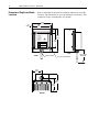
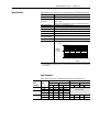
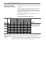
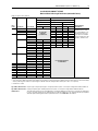
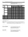
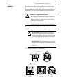
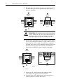
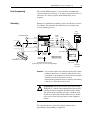
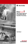
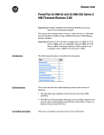
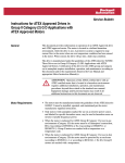
Instructions
1204 Terminator (Class 1, Division 2)
(Catalog Number 1204-TFA1, 1204-TFB2)
Where this Option is Used
The 1204 Terminator Option can be installed in most adjustable
frequency AC drive applications to increase protection of the AC
motor. The option is designed to be used with Allen-Bradley
Adjustable frequency AC drives. When installed at the motor
terminals, the terminator can reduce potentially destructive reflected
wave spikes that can occur with long motor leads.
What this Option Contains
The Terminator Option contains the terminator device with an
attached 3 meter (10 feet) standard 4 wire 3mm2 (12 gauge)
connection cable.
What these Instructions
Contain
These instructions contain the information you need to properly
install the Terminator Option. Recommended mounting, connecting,
and grounding procedures are included. Major topics and page
numbers are listed below.
Catalog Number Description . . . . . . . . . . . . . . . . . . . . . . . . . . . . . . . . . . . . . . . . . . . . . . 1
Dimensions, Weights and Cable Locations . . . . . . . . . . . . . . . . . . . . . . . . . . . . . . . . . . . 2
Specifications . . . . . . . . . . . . . . . . . . . . . . . . . . . . . . . . . . . . . . . . . . . . . . . . . . . . . . . . . 3
Heat Dissipation . . . . . . . . . . . . . . . . . . . . . . . . . . . . . . . . . . . . . . . . . . . . . . . . . . . . . 3
Determining the Maximum Cable Length for Your System . . . . . . . . . . . . . . . . . . . . . . . 4
Installation . . . . . . . . . . . . . . . . . . . . . . . . . . . . . . . . . . . . . . . . . . . . . . . . . . . . . . . . . . . . 7
Drive Programming . . . . . . . . . . . . . . . . . . . . . . . . . . . . . . . . . . . . . . . . . . . . . . . . . . . . . 9
Grounding . . . . . . . . . . . . . . . . . . . . . . . . . . . . . . . . . . . . . . . . . . . . . . . . . . . . . . . . . . . . 9
Maintenance . . . . . . . . . . . . . . . . . . . . . . . . . . . . . . . . . . . . . . . . . . . . . . . . . . . . . . . . . 10
Catalog Number Description
The following table provides information about the catalog number
for the Terminator Option:
1204
F
B2
First Position
–T
Second Position
Third Position
Fourth Position
Bulletin No.
Type
NEMA Rating
Voltage Rating & Size
Description
Letter Description
Letter
Description
Voltage
Code Rating
Bulletin
Number
T
F
NEMA Type 4
A1
Terminator
B2
Drive
kW (HP) 1
Maximum
Allowable Drive
Carrier Frequency
380-600V 0.37-3.7 6 kHz
(0.5-5)
380-600V 1.5-597 2 kHz
(2.0-800)
1 Refer to the maximum cable length tables on pages 4 through 6.
2
1204 Terminator (Class 1, Division 2)
Dimensions, Weights and Cable
Locations
6.4
(0.25)
Refer to the following diagram for terminator dimensions and cable
locations. The dimensions are given in millimeters and (inches). The
terminator weighs 3.86 kilograms (8.5 pounds).
182.9
(7.20)
170.2
(6.70)
14.2
(0.56)
Allen-Bradley
Motor Terminator
Bulletin 1204–TFXX Series A
AC Drive HP ZZZZ
Voltage WWWW VAC
Max. Carrier Freq. Y KHz
Type 4X Enclosure
Hazardous Locations
Class I, Division 2
Groups A, B, C, D
Temperature Code T3 (200˚ c)
C
UL
®
155.5
(6.12)
US
LISTED
IND. CONT. EQ.
FOR USE IN HAZ. LOC.
8AA4
Assembled in Mexico
DANGER
127.0
(5.00)
CAN CAUSE SHOCK,
BURNS, OR DEATH
DISCONNECT AND LOCKOUT
ALL POWER SOURCES
BEFORE SERVICING
SURFACES
MAY BE HOT
ALLOW TO COOL
BEFORE SERVICING
See Instruction Manual For Mounting Instructions
SIDE
FRONT
Out-Going Cable
(4) Slots for M4 Hardware
88.9
(3.50)
117.9
(4.64)
BOTTOM
158.8
(6.25)
Approximately
3048 (120)
1204 Terminator (Class 1, Division 2)
Specifications
3
The following specifications are provided for the Terminator Option.
Category
Input power
Maximum Drive Carrier
Frequency 1
Specifications
380-600V, Three-Phase
TFA1 – 6 kHz
TFB2 – 2 kHz
Refer to “Drive Programming” on page 9 for additional information.
0-40 degrees C (32-104 degrees F)
5-95% non-condensing
Class 1, Division 2
Refer to the heat dissipation table below.
IP65 (NEMA Type 4x)
T3 (200° C); Groups A, B, C, D
Ambient temperature
Humidity
Atmosphere
Heat dissipation 1
Enclosure type
Hazardous
Environment Rating
Agency certification
Altitude derating
U.L., C-UL
Full rating 0-1000 meters (0-3280 feet)
degrees C.
40
Ambient
Temperature
Limit
35
30
0
1,000
(3,300)
2,000
(6,600)
3,000
(9,900)
m
4,000
(13,200) (ft)
Altitude
1
The drive PWM carrier frequency that you choose affects the heat dissipation and the surface temperature
of the terminator.
Heat Dissipation
This chart is based on an ambient temperature of 45 degrees C.
Drive
Length
Frequency meters (feet)
6 kHz
91 (300)
183 (600)
4 kHz
91 (300)
183 (600)
2 kHz
91 (300)
183 (600)
1204-TFA1 Terminator
460 Volts + 10% 600 Volts + 10%
1204-TFB2 Terminator
460 Volts + 10% 600 Volts + 10%
Watts
Watts
210W
250W
170W
180W
80W
90W
Heatsink°
142° C
160° C
125° C
130° C
81° C
88° C
Watts
220W
260W
180W
210W
100W
140W
Heatsink°
150° C
169° C
133° C
138° C
95° C
104° C
Heatsink°
Watts
Heatsink°
Must Use 2 kHz
200W 139° C
250W 160° C
290W 182° C
360W 200° C
4
1204 Terminator (Class 1, Division 2)
Determining the Maximum
Cable Length for Your System
Use the following tables to determine the maximum cable length for
your system.
The values shown are for nominal input voltage and a drive carrier
frequency of 2 kHz. If you plan to operate your system at carrier
frequencies above 2 kHz, refer to the heat dissipation table on page 3.
If you plan to operate your system above the levels listed in the heat
dissipation table, consult the factory.
If you are running at high-line conditions (nominal line + 10%),
multiply the values by 0.85.
1305 Drive Maximum Motor Cable Length Restrictions
Lengths are given in meters and (feet)
w/ 1204–TFB2 Terminator
w/ 1204–TFA1 Terminator
Motor Type
Motor Type
A or B
A
Cable Type
B
Cable Type
Cable Type
Drive HP
(460V)
Motor HP
(460V)
Shielded
Unshielded
Shielded
Unshielded
Shielded
Unshielded
0.5
1
0.5
0.5
1
0.5
1
2
1
2
3
2
3
5
NR
NR
NR
91 (300)
61 (200)
NR
91 (300)
91 (300)
NR
121 (400)
91 (300)
NR
NR
NR
NR
121 (400)
61 (200)
NR
182 (600)
121 (400)
NR
182 (600)
121 (400)
NR
NR
76 (250)
45 (150)
99 (325)
99 (325)
91 (300)
99 (325)
99 (325)
91 (300)
99 (325)
99 (325)
91 (300)
NR
61 (200)
61 (200)
61 (200)
61 (200)
61 (200)
61 (200)
61 (200)
61 (200)
61 (200)
61 (200)
61 (200)
NR
76 (250)
45 (150)
152 (500)
121 (400)
91 (300)
182 (600)
152 (500)
91 (300)
182 (600)
152 (500)
91 (300)
NR
121 (400)
76 (250)
121 (400)
121 (400)
121 (400)
121 (400)
121 (400)
121 (400)
121 (400)
121 (400)
121 (400)
2
3
5
With Allen-Bradley
1329R/L Motors
For applications/ installations using new
motors, no restrictions in lead length due to
voltage reflection are necessary. You should
observe standard practices for voltage drop,
cable capacitance, and other issues.
NR = Not Recommended.
Type A Motor Characteristics: No phase paper or misplaced phase paper, lower quality insulation systems, corona inception voltages between 850 and 1000 volts.
Type B Motor Characteristics: Properly placed phase paper, medium quality insulation systems, corona inception voltages between 1000 and 1200 volts.
1329R/L Motors:
These AC variable speed motors are “Power Matched” for use with Allen-Bradley drives. Each motor is energy efficient and designed
to meet or exceed the requirements of the Federal Energy Act of 1992. All 1329R/L motors are optimized for variable speed operation
and include premium inverter grade insulation systems which meet or exceed NEMA MG1. Part 31.40.4.2.
1204 Terminator (Class 1, Division 2)
5
1336 PLUSPLUS II/IMPACT™/FORCE
Maximum Motor Cable Length Restrictions (380-480 Volt Drives)1
Lengths are given in meters and (feet)
w/1204-TFB2 Terminator
Drive
Frame
A1
A2
A3
A4
B
C
D
E
F
G
H
Motor Type
A or B
A
Cable Type
Drive kW (HP)
0.37 (0.5)
0.75 (1)
0.75 (1)
1.2 (1.5)
Motor kW (HP)
0.37 (0.5)
0.75 (1)
0.37 (0.5)
1.2 (1.5)
0.75 (1)
0.37 (0.5)
1.5 (2)
1.5 (2)
1.2 (1.5)
0.75 (1)
0.37 (0.5)
2.2 (3)
2.2 (3)
1.5 (2)
0.75 (1)
0.37 (0.5)
3.7 (5)
3.7 (5)
2.2 (3)
1.5 (2)
0.75 (1)
0.37 (0.5)
5.5-7.5 (7.5-10)
5.5-7.5 (7.5-10)
5.5-22 (7.5-30)
5.5-22 (7.5-30)
30-45 (X40-X60)
30-45 (40-60)
45-112 (60-X150)
45-112 (60-150)
112-187 (150-250) 112-224 (150-300)
187-336 (250-450) 187-336 (250-450)
187-448 (X250-600) 187-448 (250-600)
552-597 (700-800) 522-597 (700-800)
w/1204-TFA1 Terminator
Motor Type
Shld. 2
Cable Type
Unshld.
Use 1204-TFA1
Terminator
or 1329R/L Motor
91.4 (300)
91.4 (300)
182.9 (600)
182.9 (600)
182.9 (600)
182.9 (600)
182.9 (600)
182.9 (600)
182.9 (600)
182.9 (600)
182.9 (600)
182.9 (600)
182.9 (600)
182.9 (600)
182.9 (600)
182.9 (600)
182.9 (600)
182.9 (600)
182.9 (600)
182.9 (600)
182.9 (600)
B
91.4 (300)
182.9 (600)
182.9 (600)
182.9 (600)
182.9 (600)
182.9 (600)
182.9 (600)
182.9 (600)
182.9 (600)
182.9 (600)
182.9 (600)
182.9 (600)
182.9 (600)
182.9 (600)
182.9 (600)
182.9 (600)
182.9 (600)
182.9 (600)
182.9 (600)
182.9 (600)
182.9 (600)
Cable Type
Shld.2
Unshld.
Shld.2
Unshld.
30.5 (100)
30.5 (100)
30.5 (100)
30.5 (100)
30.5 (100)
30.5 (100)
30.5 (100)
30.5 (100)
30.5 (100)
30.5 (100)
61.0 (200)
30.5 (100)
61.0 (200)
30.5 (100)
30.5 (100)
30.5 (100)
30.5 (100)
30.5 (100)
30.5 (100)
30.5 (100)
30.5 (100)
30.5 (100)
30.5 (100)
61.0 (200)
61.0 (200)
61.0 (200)
91.4 (300)
91.4 (300)
91.4 (300)
91.4 (300)
61.0 (200)
30.5 (100)
61.0 (200)
61.0 (200)
61.0 (200)
61.0 (200)
61.0 (200)
61.0 (200)
61.0 (200)
61.0 (200)
With Allen-Bradley
1329R/L Motors
For applications/ installations
using new motors, no restrictions in lead length due to voltage reflection are necessary.
You should observe standard
practices for voltage drop, cable
capacitance, and other issues.
Use 1204-TFB2 Terminator
or 1329R/L Motor
NR = Not Recommended
1 Values shown are for 480V nominal input voltage and drive carrier frequency of 2 kHz. Consult factory regarding operation at carrier frequencies above 2 kHz. Multiply
values by 0.85 for high line conditions. For input voltages of 380, 400 or 415V AC, multiply the table values by 1.25, 1.20 or 1.15, respectively.
2 Includes wire in conduit.
Type A Motor Characteristics: No phase paper or misplaced phase paper, lower quality insulation systems, corona inception voltages between 850 and 1000 volts.
Type B Motor Characteristics: Properly placed phase paper, medium quality insulation systems, corona inception voltages between 1000 and 1200 volts.
1329R/L Motors:
These AC variable speed motors are “Power Matched” for use with Allen-Bradley drives. Each motor is energy efficient and designed
to meet or exceed the requirements of the Federal Energy Act of 1992. All 1329R/L motors are optimized for variable speed operation
and include premium inverter grade insulation systems which meet or exceed NEMA MG1. Part 31.40.4.2.
6
1204 Terminator (Class 1, Division 2)
1336 PLUS/PLUS II/IMPACT™/FORCE
Maximum Motor Cable Length Restrictions (500-600 Volt Drives)1
Lengths are given in meters and (feet)
w/1204-TFB2 Terminator
w/1204-TFA1 Terminator
Motor Type
Motor Type
Drive
Frame
A
B
1329R/L
A
Drive kW (HP)
Motor kW (HP)
Any Cable
Any Cable
Any Cable
Any Cable Any Cable
Any Cable
A4
0.75 (1)
0.75 (1)
0.37 (0.5)
1.5 (2)
1.2 (1.5)
0.75 (1)
0.37 (0.5)
2.2 (3)
1.5 (2)
0.75 (1)
0.37 (0.5)
3.7 (5)
2.2 (3)
1.5 (2)
0.75 (1)
0.37 (0.5)
5.5-15(7.5-20)
18.5-45 (25-60)
56-93 (75-125)
112-224 (150-X300)
187-336 (250-450)
224-448 (300-600)
522-597 (700-800)
NR
NR
NR
NR
NR
NR
NR
NR
NR
NR
NR
NR
NR
NR
NR
91.4 (300)
91.4 (300)
91.4 (300)
91.4 (300)
91.4 (300)
91.4 (300)
91.4 (300)
182.9 (600)
182.9 (600)
182.9 (600)
182.9 (600)
182.9 (600)
182.9 (600)
182.9 (600)
182.9 (600)
182.9 (600)
182.9 (600)
182.9 (600)
182.9 (600)
182.9 (600)
182.9 (600)
182.9 (600)
182.9 (600)
182.9 (600)
182.9 (600)
182.9 (600)
182.9 (600)
182.9 (600)
182.9 (600)
335.3 (1100)
335.3 (1100)
335.3 (1100)
335.3 (1100)
335.3 (1100)
335.3 (1100)
335.3 (1100)
335.3 (1100)
335.3 (1100)
335.3 (1100)
335.3 (1100)
335.3 (1100)
335.3 (1100)
335.3 (1100)
335.3 (1100)
NR
NR
NR
NR
NR
NR
NR
NR
NR
NR
NR
NR
NR
NR
NR
NR
NR
NR
NR
NR
NR
NR
182.9 (600)
182.9 (600)
182.9 (600)
182.9 (600)
182.9 (600)
182.9 (600)
182.9 (600)
182.9 (600)
182.9 (600)
182.9 (600)
182.9 (600)
182.9 (600)
182.9 (600)
182.9 (600)
182.9 (600)
182.9 (600)
182.9 (600)
182.9 (600)
182.9 (600)
182.9 (600)
182.9 (600)
182.9 (600)
1.5 (2)
2.2 (3)
3.7 (5)
B
C
D
E
F
G
H
5.5-15 (7.5-20)
18.5-45 (25-60)
56-93 (75-125)
112-224 (150-X300)
187-336 (250-450)
224-448 (300-600)
522-597 (700-800)
2
2
2
2
2
2
2
B
With
Allen-Bradley
1329R/L Motors
61.0 (200)
61.0 (200)
61.0 (200)
61.0 (200)
61.0 (200)
61.0 (200)
61.0 (200)
61.0 (200)
61.0 (200)
61.0 (200)
61.0 (200)
61.0 (200)
61.0 (200)
61.0 (200)
61.0 (200)
61.0 (200)
61.0 (200)
61.0 (200)
61.0 (200)
61.0 (200)
61.0 (200)
61.0 (200)
NR = Not Recommended
1 Values shown are for nominal input voltage and drive carrier frequency of 2 kHz. Consult factory regarding operation at carrier frequencies above 2 kHz. Multiply values
by 0.85 for high line conditions.
2 Information not available at time of printing.
Type A Motor Characteristics: No phase paper or misplaced phase paper, lower quality insulation systems, corona inception voltages between 850 and 1000 volts.
Type B Motor Characteristics: Properly placed phase paper, medium quality insulation systems, corona inception voltages between 1000 and 1200 volts.
1329R/L Motors:
These AC variable speed motors are “Power Matched” for use with Allen-Bradley drives. Each motor is energy efficient and designed
to meet or exceed the requirements of the Federal Energy Act of 1992. All 1329R/L motors are optimized for variable speed operation
and include premium inverter grade insulation systems which meet or exceed NEMA MG1. Part 31.40.4.2.
PowerFlex 70/700/700H
See the PowerFlex Reference Manual, Volume 1,
publication PFLEX-RM001 available online at
www.rockwellautomation.com/literature.
PowerFlex 700S
See the PowerFlex Reference Manual, Volume 2,
publication PFLEX-RM002 available online at
www.rockwellautomation.com/literature.
1204 Terminator (Class 1, Division 2)
Installation of the 1204 Terminator must be in accordance with
Class I, Division 2 wiring methods as defined in Article 501-4(b) of
the National Electrical Code, NFPA 70 for installations within the
United States, or as specified in Section 18-152 of the Canadian
Electrical Code for installation within Canada.
WARNING: EXPLOSION HAZARD
!
• Substitution of components may impair suitability for
Class I, Division 2.
• When in hazardous locations, turn off power before
replacing or wiring modules.
• Do not disconnect equipment unless power has been
switched off or the area is known to be nonhazardous.
To install the terminator, follow these steps:
1. Remove all power connected to the system.
ATTENTION: Electric shock can cause injury or
death. Remove all power before working with this
product. Verify that the voltage on the bus capacitors
has discharged. Measure the DC bus voltage at the +
and – terminals of TB1. The voltage must be zero.
!
ATTENTION: The terminator surfaces may be hot
enough to cause serious burns. You should take this into
consideration when deciding where to mount your
terminator.
2. Mount the terminator on a metal surface.
Metal Surface
Top View
Top View
Important: Heatsink Fins Must be Vertical.
Air Flow
Allen-Bradley
Motor Terminator
US
DANGER
TE
D 966
®
IND
E
C O NT
LI S
SURFACES
MAY BE HOT
Motor Terminator
LI S
D 966
Made in U.S.A.
Q
Q
TE
®
IND
E
C O NT
ALLOW TO COOL
BEFORE SERVICING
SURFACES
MAY BE HOT
DISCONNECT AND LOCKOUT
ALL POWER SOURCES
BEFORE SERVICING
DISCONNECT AND LOCKOUT
ALL POWER SOURCES
BEFORE SERVICING
CAN CAUSE SHOCK,
BURNS, OR DEATH
CAN CAUSE SHOCK,
BURNS, OR DEATH
DANGER
X
®
Allen-Bradley
UL
Bulletin 1204-TFB2 Series A
AC Drive HP .5 to 600
Voltage 380-600 VAC
Carrier Freq. ≤ 2 KHz
C
LISTED
IND. CONT. EQ.
FOR USE IN HAZ. LOC.
8AA4
Assembled in Mexico
See Instruction Manual For Mounting Instructions
Bulletin 1204–TFXX Series A
AC Drive HP ZZZZ
Voltage WWWW VAC
Max. Carrier Freq. Y KHz
Type 4X Enclosure
Hazardous Locations
Class I, Division 2
Groups A, B, C, D
Temperature Code T3 (200˚ c)
X
Installation
7
ALLOW TO COOL
BEFORE SERVICING
See Instruction Manual For Mounting Instructions
Front View
Front View
Front View
8
1204 Terminator (Class 1, Division 2)
3. You must allow at least 152.4 mm (6 in.) on each side of the unit
and 304.8 mm (12 in.) on the top and bottom of the unit for
proper air circulation.
304.8 mm
(12.0 in.)
Allen-Bradley
152.4 mm
(6.0 in.)
Motor Terminator
Bulletin 1204–TFXX Series A
AC Drive HP ZZZZ
Voltage WWWW VAC
Max. Carrier Freq. Y KHz
Type 4X Enclosure
Hazardous Locations
Class I, Division 2
Groups A, B, C, D
Temperature Code T3 (200˚ c)
C
UL
®
US
LISTED
IND. CONT. EQ.
FOR USE IN HAZ. LOC.
8AA4
Assembled in Mexico
DANGER
152.4 mm
(6.0 in.)
152.4 mm
(6.0 in.)
CAN CAUSE SHOCK,
BURNS, OR DEATH
DISCONNECT AND LOCKOUT
ALL POWER SOURCES
BEFORE SERVICING
SURFACES
MAY BE HOT
ALLOW TO COOL
BEFORE SERVICING
152.4 mm
(6.0 in.)
152.4 mm
(6.0 in.)
See Instruction Manual For Mounting Instructions
Top View
304.8 mm
(12.0 in.)
Front View
ATTENTION: The terminator surfaces may be hot enough
to cause serious burns. If your system consistently runs at
line voltages above nominal, you should place a shroud
around the terminator to prevent accidental exposure.
!
4. If your system consistently runs at line voltages above nominal
and you are mounting the terminator in a high-traffic area where
the potential for contact is high, you should place a shroud of
expanded metal or mesh screen around the terminator. The shroud
should not restrict air flow to the terminator, nor should it be
closer than 152.4 mm (6 in.) to the terminator at any point.
152.4 mm
(6.0 in.)
Allen-Bradley
Motor Terminator
Bulletin 1204–TFXX Series A
AC Drive HP ZZZZ
Voltage WWWW VAC
Max. Carrier Freq. Y KHz
Type 4X Enclosure
Hazardous Locations
Class I, Division 2
Groups A, B, C, D
Temperature Code T3 (200˚ c)
C
UL
®
152.4 mm
(6.0 in.)
LISTED
IND. CONT. EQ.
FOR USE IN HAZ. LOC.
8AA4
Assembled in Mexico
152.4 mm
(6.0 in.)
152.4 mm
(6.0 in.)
US
DANGER
CAN CAUSE SHOCK,
BURNS, OR DEATH
DISCONNECT AND LOCKOUT
ALL POWER SOURCES
BEFORE SERVICING
SURFACES
MAY BE HOT
152.4 mm
(6.0 in.)
152.4 mm
(6.0 in.)
ALLOW TO COOL
BEFORE SERVICING
See Instruction Manual For Mounting Instructions
Shroud
152.4 mm
(6.0 in.)
Shroud
Top View
Front View
5. Connect the red, white and black cable conductors to the
corresponding three-phase motor leads/terminals.
6. Attach the green cable conductor to the motor ground that is
connected directly to the drive PE terminal.
1204 Terminator (Class 1, Division 2)
9
Drive Programming
If the default PWM frequency is greater than the maximum drive
carrier frequency listed on page 3, you must re-program the drive to a
value that is less than or equal to the maximum drive carrier
frequency.
Grounding
Follow the recommended grounding practices provided in your drive
User Manual. The following illustration shows an example of the
system grounding practices.
Motor
Terminator*
Conduit/4-Wire Cable
R (L1)
U (T1)
Common
Mode
Shield*
Core*
Allen-Bradley
Motor Terminator
Bulletin 1204–TFXX Series A
AC Drive HP ZZZZ
Voltage WWWW VAC
Max. Carrier Freq. Y KHz
Type 4X Enclosure
Hazardous Locations
Class I, Division 2
Groups A, B, C, D
Temperature Code T3 (200˚ c)
C
UL
®
US
LISTED
IND. CONT. EQ.
FOR USE IN HAZ. LOC.
8AA4
Assembled in Mexico
DANGER
CAN CAUSE SHOCK,
BURNS, OR DEATH
DISCONNECT AND LOCKOUT
ALL POWER SOURCES
BEFORE SERVICING
SURFACES
MAY BE HOT
ALLOW TO COOL
BEFORE SERVICING
See Instruction Manual For Mounting Instructions
ESC
S (L2)
V (T2)
SEL
JOG
W (T3)
PE/Gnd.
T (L3)
Shield
PE
Motor Frame
RIO/DH+
or Analog
Nearest
Building Structure Steel
Common
Mode Core*
* Options that can be
installed as needed.
To Computer/Position Controller
(for TE shield ground, see "Control and Signal Wiring")
Motor Frame
PE
Ground per
Local Codes
Important: If you cannot connect the terminator directly to the motor
mounted junction box, an auxiliary junction box can be
used. However, the terminator-to-motor connection length
should be no more than 6 meters (20 feet).
If installed in hazardous location, an auxiliary junction box
rated Class 1, Division 2 must be used.
!
ATTENTION: The National Codes and standards (NEC,
VDE, BSI, etc.) and local codes outline provisions for safely
installing electrical equipment. Installation must comply
with specifications regarding wire types, conductor sizes,
branch circuit protection, and disconnect devices. Failure
to do so may result in personal injury and/or equipment
damage.
You can power up the system once proper installation, drive
programming, and grounding is completed.
10
1204 Terminator (Class 1, Division 2)
Maintenance
The terminator does not require routine maintenance. However, you
should periodically remove dust to allow for maximum cooling
efficiency.
!
ATTENTION: Electric shock can cause injury or death.
Remove all power before touching the terminator.
!
ATTENTION: The terminator surfaces may be hot enough
to cause serious burns. Allow the terminator time to cool
down before touching any surface.
1204 Terminator (Class 1, Division 2)
Notes
11
www.rockwellautomation.com
Power, Control and Information Solutions Headquarters
Americas: Rockwell Automation, 1201 South Second Street, Milwaukee, WI 53204 USA,Tel: (1) 414.382.2000, Fax: (1) 414.382.4444
Europe/Middle East/Africa: Rockwell Automation, Vorstlaan/Boulevard du Souverain 36, 1170 Brussels, Belgium,Tel: (32) 2 663 0600, Fax: (32) 2 663 0640
Asia Pacific: Rockwell Automation, Level 14, Core F, Cyberport 3, 100 Cyberport Road, Hong Kong,Tel: (852) 2887 4788, Fax: (852) 2508 1846
Publication 1204-5.0 – July 2005
Supersedes May 2005
P/N 74002-112-01 (04)
Copyright © 2005 Rockwell Automation, Inc. All rights reserved. Printed in USA.