1
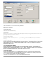
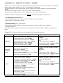
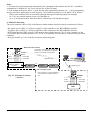
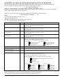
QA8
From Version 8.01.60
USER MANUAL
10ue800 QA8 User Manual.doc
1 January, 2003
TABLE OF CONTENTS
1. INSTALLATION: ........................................................................................................................................................................ 4
1.1 NEW INSTALLATION ................................................................................................................................................................. 4
1.2 UPGRADE FROM A PREVIOUS VERSION: ................................................................................................................................... 4
2. ACCESSING THE PROGRAMME - MAIN MENU ............................................................................................................... 5
2.1 LOGIN MENU ............................................................................................................................................................................ 5
2.2 COMMUNICATION STATUS ....................................................................................................................................................... 5
2.3 MAIN SCREEN BUTTONS .......................................................................................................................................................... 5
2.4 LOGO........................................................................................................................................................................................ 5
3. PARAMETERS MENU............................................................................................................................................................... 6
3.1 STATION ................................................................................................................................................................................... 6
3.2 READER.................................................................................................................................................................................... 6
3.2.1 Reader Name. .................................................................................................................................................................. 7
3.2.2 Station.............................................................................................................................................................................. 7
3.2.3 Controller address ........................................................................................................................................................... 7
3.2.4 Controller Type................................................................................................................................................................ 7
3.2.5 Controller Doors Number................................................................................................................................................ 7
3.2.6 Reader Number................................................................................................................................................................ 7
3.2.7 Access Criteria................................................................................................................................................................. 8
3.2.8 Badge Format .................................................................................................................................................................. 8
3.2.9 General Keypad code ...................................................................................................................................................... 9
3.2.10 Supervisor function........................................................................................................................................................ 9
3.2.11 Anti pass back. ............................................................................................................................................................. 10
3.2.12 Counting. ..................................................................................................................................................................... 10
3.2.13 Close Door if Buffer full .............................................................................................................................................. 10
3.2.14 Door Open Delay......................................................................................................................................................... 10
3.2.15 Door Alarm Delay and Door Alarm Mode .................................................................................................................. 10
3.2.16 Weekly Program and door modes................................................................................................................................ 11
3.2.17 Reader locked when input is active.............................................................................................................................. 11
3.3 BADGE FORMAT ..................................................................................................................................................................... 11
3.4 DAILY PROGRAMS .................................................................................................................................................................. 12
3.5 WEEKLY PROGRAMS .............................................................................................................................................................. 12
3.6 HOLIDAYS .............................................................................................................................................................................. 12
3.7 ACCESS GROUP ...................................................................................................................................................................... 12
3.8 CARDHOLDERS ....................................................................................................................................................................... 13
3.8.1 Card Number ................................................................................................................................................................. 14
3.8.2 Card Code...................................................................................................................................................................... 14
3.8.3 Access Group ................................................................................................................................................................. 14
3.8.4 Validated........................................................................................................................................................................ 14
3.8.5 PIN Code ....................................................................................................................................................................... 14
3.8.6 Supervisor...................................................................................................................................................................... 14
3.8.7 Credit ............................................................................................................................................................................. 15
3.8.8 Validated Until............................................................................................................................................................... 15
3.9 INPUT ALARM ........................................................................................................................................................................ 15
3.10 RELAY................................................................................................................................................................................ 16
3.11 LOCAL REFLEXES. .......................................................................................................................................................... 16
3.12 LIFT .................................................................................................................................................................................... 16
4. COMMUNICATION MENU.................................................................................................................................................... 17
5. JOURNAL MENU ..................................................................................................................................................................... 17
6. UTILITY MENU........................................................................................................................................................................ 18
6.1 CREATE NEW DATABASE........................................................................................................................................................ 18
6.2 SAVE DATABASE .................................................................................................................................................................... 18
6.3 RESTORE DATABASE .............................................................................................................................................................. 18
6.4 CHANGE PASSWORD............................................................................................................................................................... 18
QA8: User Manual
Document: ‘10ue800 QA8 User Manual.doc’ Issue 01.01.2003
Page 2/24
6.5 DOORS AND RELAYS CONTROL.............................................................................................................................................. 18
6.6 CREATE A GROUP OF CARDHOLDERS ..................................................................................................................................... 18
6.7 DISABLE COMMUNICATION .................................................................................................................................................... 18
6.8 WRITE COMMUNICATION LOG ............................................................................................................................................... 18
6.9 AUTO DETECTION ................................................................................................................................................................... 18
6.10 TIME AND ATTENDANCE ...................................................................................................................................................... 18
APPENDIX A.1: REMOTE STATIONS - MODEM................................................................................................................. 19
APPENDIX A.2: BACKUP FILES FROM TRANSACTIONS TRANSFER........................................................................... 21
APPENDIX A.3: AUTO READ TRANSACTIONS.................................................................................................................... 22
Autoread=0............................................................................................................................................................................. 22
AutoShowJournal=0 ............................................................................................................................................................... 22
APPENDIX A.4: SENDING SCRIPT WITH EVERY GENERAL DOWNLOAD ................................................................. 23
APPENDIX A.5: QA8.INI ENTRIES........................................................................................................................................... 24
AutoRead ................................................................................................................................................................................ 24
AutoTimer ............................................................................................................................................................................... 24
AutoShowJournal.................................................................................................................................................................... 24
DailyPrograms4Zones............................................................................................................................................................ 24
AllTPLD4D............................................................................................................................................................................. 24
GroupMode............................................................................................................................................................................. 24
QA8: User Manual
Document: ‘10ue800 QA8 User Manual.doc’ Issue 01.01.2003
Page 3/24
The QA8 software allows to program the NSL3, TPL3 and the NTL3 controllers from a PC.
It is a 32 bits application which may run under Windows 95, 98, NT etc….
1. INSTALLATION:
1.1 New Installation
Insert the CD and follow the instructions.
1.2 Upgrade from a Previous Version:
Step 1. Before removing the old installation:
- Use the Utilities menu and the Journal menu in the software to save the Database and the Journal in a
different folder outside of the Quick Access folder.
- Save the eventual modem initialization file (indicated in the field ‘Init file’ of the Station screen) in a
different folder outside of the Quick Access folder.
- Check the Local Reflexes: the Local Reflexes database is different between versions 7.xx and versions
8.xx and is not updated with the version. Therefore, if version 7.xx is updated to version 8.xx, and if
Local reflexes have been used, check, before updating the version, how they have been defined to
re-define them in the new version.
Step 2. Remove the old version from your computer using the standard Windows utility.
Step 3. Insert the CD and follow the instructions.
Step 4. After installation is completed:
- Use the Utilities menu and the Journal menu in the software to restore the Database and the Journal from
the location from which they were saved.
- Copy back to the Quick Access folder the modem initialization file from the location where it was saved.
QA8: User Manual
Document: ‘10ue800 QA8 User Manual.doc’ Issue 01.01.2003
Page 4/24
2. ACCESSING THE PROGRAMME - MAIN MENU
To access the program, click on the QA8 Icon.
2.1 Login Menu
When run, the program prompts for a Password. The factory password is 123. It may be changed through
the ‘Utility/Change Password’ option.
If the ‘No Communication’ is selected, the program will not try to communicate with any controllers.
Communication may be restored further on using the ‘Enable/Disable communication’ button of the Main
Screen.
Command line:
If the parameters /pw: ‘password’ (‘password’ is the current password) is added at the properties shortcut
command line, password will not be required when entering the program. (Example: "C:\Program
Files\Quick Access 8\QA8.EXE" /pw:123)
If the /nc parameter is added after the /pw one, the QA8 will not try to communicate with the controllers.
Example: "C:\Program Files\Quick Access 8\QA8.EXE" /pw:123 /nc
Once entered, the Main Menu appears which contains two lines: a Menu line and a Button line.
2.2 Communication Status
A Communication Status windows appears on the right side of the Main Menu which indicates the status of
each reader (one per line), as follows:
- Either in Green if communication with the reader is O.K. The time and date at the reader is also shown
on the line.
- Or in Bold with a ‘Time check’ icon if the time read from the reader is at least 5 minutes different than
the time at the PC. (Time and date must then be sent to the reader, using the corresponding button)
- Or in Red with the ‘No answer’ message if the program cannot get communication with the reader. The
failure must be corrected and communication may be checked once more using the corresponding
button.
2.3 Main Screen Buttons
-
-
-
-
Cardholders: This button is a shortcut to the cards parameters, as described in paragraph 3.7
Door control: This button is a shortcut to the Door control Option of the Utility Menu as described in
par 6.5. It allows to open relays or doors in one click.
Transfer Transactions: this button is a shortcut to the ‘Transactions transfer’ option of the
Communication Menu: it allows reading and erasing the events (cardholders’ transactions and alarms)
recorded in the controllers buffer.
Display Journal: this button allows to display all the transactions previously transferred and to perform
some queries.
Get Time and Data: this button allows you to read the Time and Date of the controllers.
General Download: this button is a shortcut to the ‘General Download’ option of the Communication
Menu: it allows you to download some or all the parameters in the database to the controllers.
If you ask to reset memory before download, the QA8 will suggest reading the stored transactions prior
to memory reset.
Enable/Disable Communication: This option allows working on the QA8 without communicating with
the controllers. While working without communication - pressing the ‘Save’ and ‘Download’ buttons
would only store changes in the local database without updating the controller. After renewing the
communication, and in case such changes were done, the user must use the General Download option in
order to update the controller.
Time and Attendance: This button allows you to get total presence hours of cardholders.
Exit: Exit QA8
2.4 Logo
A Logo/image may be displayed at the Main Menu background by simply inserting the Logo or image in a
file named ‘Background.bmp’ located in the QA8 directory.
QA8: User Manual
Document: ‘10ue800 QA8 User Manual.doc’ Issue 01.01.2003
Page 5/24
3. PARAMETERS MENU
This chapter describes the options of this menu to be used, step by step, the first time the system has to be
programmed. Each option corresponds to a parameter's screen.
Once programmed, any change or update may be done in any order.
When, in a specific screen, the ‘Save’ button is pressed after a change has been done, only the changed
parameter(s) will be downloaded to the controllers.
When the “Down Load” button is pressed, all the parameters of the corresponding screen will be
downloaded.
3.1 Station
A station is a group of controllers connected to a same PC serial Com port. A station is defined by:
- The Com port number to which the controllers are connected. (from 1 to 4)
- The communication speed with the controllers. Default speed is 4800bps.
On controllers from Eprom version 01-04-2002 , the programmable baud rate up to 38400bps.
Changing the speed in Station screen sets the QA8 to the new speed and also configures the controllers
to the new speed. Since such a change is done per station, it is recommended to do it only after all the
readers were defined.
Note that all the controllers in the specific station should be from Eprom version 01-04-2002 or later.
- The time out delay the program waits for a controller answer. If no answer is received after this delay,
the program will display a warning message
- The waiting delay the program will wait between two commands to be sent to the controllers.
Notes:
1- If the station is remote, i.e. connected to the program through modems, define the phone number of the
remote modem and the ‘Initialization file’, which is a list of commands the program will sent to the
calling modem near the PC to establish the connection. (See Appendix A).
2- If the station is connected through TCP/IP network, read the ‘09te008 RS485 TCP/IP Interface’
document for details.
3.2 Reader
There are 3 types of controllers: NSL3, TPL3, TPL3-D4
NSL3: up to 2 doors / 2 readers
TPL3: up to 2 doors / 4 readers
TPL3-D4: up to 4 doors / 4 readers
The number of readers DOES NOT have to match the number of doors. It is possible, in the TPL3-D4 for
instance, to have 4 readers but just 3 doors. In this case two of the readers will be for doors which have just
one reader, while the other two will be for a single door with 2 readers (IN/OUT).
The user sets the <Controller Doors Number> (i.e., the total number of doors which will be connected to the
controller) and the <reader number> (i.e., the specific reader number on the controller, from 1 to 4). Then,
the QA8 will show a blue message to indicate the function of this controller.
See image on next page.
QA8: User Manual
Document: ‘10ue800 QA8 User Manual.doc’ Issue 01.01.2003
Page 6/24
This screen allows to set the various reader parameters.
Sub screen “ General ”:
3.2.1 Reader Name.
This field is for information only.
3.2.2 Station
Indicate here the station to which the reader, through its controller, belongs. This station must have been
previously defined, as described in Par.3.1.
3.2.3 Controller address
The address of the controller, from 01 to 16, is defined by its on-board DIP-switch. (See installation
Manual).
3.2.4 Controller Type
Sets the controller type according to the actual hardware connected. The program will take it into account
when setting the next field <Controller Doors Number>. NSL3 or TPL3, for example, will not allow
defining more than 2 doors.
3.2.5 Controller Doors Number
Sets the total number of doors (up to 4) that are controlled from this controller. This definition is per
controller. Hence, if while defining reader 1 it is set to 2 doors, and later, for reader 2 it is set it to 4 doors,
then the corresponding field of reader 1 will be auto set 4 doors as well.
3.2.6 Reader Number
Sets the reader number from 1 to 4 to which the actual reader was connected on the controller board.
The QA8 will calculate the function of the reader, based on the definitions here and the previous field
(i.e., <Controller Doors Number> and <Reader Number>).
The result of the calculation will be shown in blue fonts under this field.
QA8: User Manual
Document: ‘10ue800 QA8 User Manual.doc’ Issue 01.01.2003
Page 7/24
Example: Controller Doors Number is <2 doors> and reader number is <reader 3>, the blue message will
be “Exit Door 1”. It means that the corresponding relay controlled by this reader is relay 1.
The default settings of the inputs/outputs/local reflexes of each controller is automatically set according to
the Controller Doors Number as follows:
1-door system
Door relay: readers 1,2,3,4 control relay No.1 (door 1)
Door control (for door alarm): Input No.1 (1)
Door remote: Input No.3
General alarm: Inputs No.2, 4, 5, 6, 7, 8, in N.O (2) (3)
2-door system
Door relay: readers 1,3 control relay No.1 (door 1)
readers 2,4 control relay No.2 (door 2)
Door control (for door alarm): I1, I2 for door 1,2 (1)
Door remote (NO): I3, I4 for door 1,2
General alarm: Inputs No.5, 6, 7, 8, in N.O. (2) (3)
3-door system
Door relay: readers 1,3 control relay No.1 (door 1)
reader 2 controls relay No.2 (door 2)
reader 4 controls relay No.3 (door 3)
Door control (for door alarm): I1, I2, I5 for doors 1, 2, 3 (1)
Door remote (NO): I3, I4, I7 for doors 1,2,3
General alarm: Inputs No.6, 8 in N.O. (2) (3)
4-door system
Door relay: Reader 1controls relay No.1 (door 1)
Reader 2 controls relay No.2 (door 2)
Reader 3 controls relay No.3 (door 3)
Reader 4 controls relay No.4 (door 4)
Door control (for door alarm): I1, I2, I5, I6 for doors 1, 2,3, 4 (1) (3)
Door remote (NO): I3, I4, I7, I8 for doors 1, 2, 3, 4
3.2.7 Access Criteria
To get access, a person must either swipe a card or key-in a keypad code or both, according to the system
Access Criteria programmed.
3.2.8 Badge Format
On TPL3-D4 from firmware from 03-09-2002 and later, it is possible to set a different reader technology for
each reader. It is done by setting DIP-Switch 6=OFF, 7=OFF, 8=ON and selecting the corresponding
technology in this field. A new installation of QA8 will have just one default technology but it is possible to
modify it as well as set other formats along with available technologies in Badge Format screen.
See paragraph 3.3 Badge Format.
(1)
Door alarm (input default in NO) is raised if the door is forced or left opened more than a pre-defined delay (10 sec. by
default).
This alarm consists of a message recorded and printed and the activation of relay No.3 (in a 1 or 2 door system) or relay No.4 (in
a 3 door system) or relay No.5 of an extension board (in a 4 door system) until the door is closed back.
(2)
General alarms consist of a message recorded and printed and the activation of relays No.4 (in a 1 or 2 door system) or relay
No.5 (in a 3 door system) until the input is deactivated.
(3)
Status of each alarm input (N.O. or N.C.) and its time zone may be Programmed through the ‘Input Alarm’ screen.
QA8: User Manual
Document: ‘10ue800 QA8 User Manual.doc’ Issue 01.01.2003
Page 8/24
3.2.9 General Keypad code
When a cardholder has to key-in a code at the reader keypad, this code may be:
- Either a general code, common to everybody, and defined in this field.
- Or its individual code (‘PIN’) defined in its database (through the ‘Cardholder’ screen), if this field is
‘0’ or left blank.
3.2.10 Supervisor function.
The Supervisor function allows to manage, by simply swiping a Supervisor badge, either the general alarm
of the controller itself (inputs I5 to I8 and in case of one door installation also I2 and I4) or an external
alarm panel, via relay 3 or 4 of the controller. A Supervisor badge is a regular badge that has been defined
as “Supervisor” in its database.
According to the type of controller and the mode selected, this Supervisor function operates as follows:
Controller NSL3:
Supervisor modes control relay No.3 as follows:
Mode 1: No relay. Relay 3 is used for door alarm as programmed in the Reader sub-screen ‘Door control’.
Mode 2: Relay 3 during open delay. Door alarm is always deactivated and relay 3 controls an external
alarm panel. Passing the Supervisor card through one of the reader will activate relay 3 during a pre-defined
delay (the same as the door open delay), a long “beep” is sound and the red led will light on for 2 seconds.
Mode 3: Relay 3 toggled. Door alarm are always deactivated and relay 3 controls an external alarm panel in
a toggle mode:
→If relay 3 is deactivated, passing the Supervisor card through one of the reader will activate it, a long
“beep” is sound and the red led will light on for 2 seconds.
→If relay 3 is activated, passing the Supervisor card through one of the reader will deactivate it, a long
“beep” is sound and the green led will light on for 2 seconds.
Controller TPL3:
Supervisor modes control relay No.4 as follows:
Mode 1: No relay. Relay 4 is used for general alarms (I5 to I8 and in case of one door installation also I2
and I4) and passing the supervisor card through one of the readers will activated / deactivated these 4 (or 6)
alarm inputs:
→If the inputs are deactivated, the Supervisor card will activate them, a long ‘beep’ will be sound and the
red led will light on for 2 seconds. And therefore, relay 4 will be activated as soon as one of the alarm inputs
I5 to I8 (and in case of one door installation also I2 and I4) is under alarm.
→If the inputs are activated, the Supervisor card will deactivate them, a long ‘beep’ will be sound and the
green led will light on for 2 seconds. And therefore, relay 4 is not activated even if one of the alarm inputs
I5 to I8 (and in case of one door installation also I2 and I4) is under alarm.
Mode 2: Relay 4 during open delay. The alarm inputs I5 to I8 (and in case of one door installation also I2
and I4) are always deactivated and relay 4 control an external alarm panel. Passing the Supervisor card
through one of the readers will activate relay 4 during a pre-defined delay (the same as the door open delay),
a long “beep” is sound and the red led will light on for 2 seconds.
Mode 3:Relay 4 toggled. The inputs I5 to I8 (and in case of one door installation also I2 and I4) are always
deactivated and relay 4 control an external alarm panel in a toggle mode:
→If relay 4 is deactivated, passing the Supervisor card through one of the reader will activate it, a long
“beep” is sound and the red led will light on for 2 seconds.
→If relay 4 is activated, passing the Supervisor card through one of the reader will deactivate it, a long
“beep” is sound and the green led will light on for 2 seconds.
Notes:
1. The Supervisor modes 2 and 3 does not deactivate local reflexes if defined. (See Par. 3.10).
2. The supervisor function is relevant only on 1 or 2 doors system. Attempting to define mode 2 or 3 on a
three or four doors system will result in communication errors.
QA8: User Manual
Document: ‘10ue800 QA8 User Manual.doc’ Issue 01.01.2003
Page 9/24
3.2.11 Anti pass back.
When this feature is checked, the same card may not access twice the same reader: it must be granted on
another reader (of the same controller) before it can be granted again on the specific reader.
There is a different behavior to this feature depending on the controller type:
TPL3/NSL3:
The anti pass back setting is done by one definition that sets all readers to Anti Passback mode. It can only
be done at reader 1 definition screen. The option is grayed out for all other readers.
TPL3-D4:
The anti pass back setting is done separately for each reader.
3.2.12 Counting.
This feature may be used only when the two readers of a same controller are used for a same door, in its two
directions (i.e. Reader No.2 defined as ‘Exit’). When this feature is activated, the controller counts the
number of cardholders “in” the system, i.e. whose access from reader No.1 and not yet exited from reader
No.2. When this number reaches 0, i.e. nobody is no more “in”, the controller will activate its relay No.2.
This relay may control an alarm or lighting system, which will be therefore automatically switched off as
soon as everybody has left.
At each access, the system will display the number of remaining persons (at its optional build-in LCD
display).
The selection of this feature may only be done from reader No.1 definition screen.
Note: Each time this command is used, (i.e., when saving/downloading the reader) it resets the number of
present person to 00.
3.2.13 Close Door if Buffer full
Some controllers , depending on the firmware, support the “Close Door if Buffer full” status. Once set, it
will not grant access nor open the door when the controller transaction buffer is full. This is in order not to
lose any transaction. If not set, each new transaction over the memory capacity will override one old
transaction in a FIFO mode, i.e., the deleted transaction will be the most old one.
Sub screen “Door Control”:
3.2.14 Door Open Delay
The door open delay defines how long the relay, which controls the door, will be operated after access has
been granted. Setting it to 99 makes the reader work in Toggle (or Alternate) Mode. In this mode, passing
the first valid card will open the door constantly. Passing the second valid card will close it constantly, and
so on. The toggle mode is supported only on the TPL3-D4 and also in some other models, depending on the
firmware version.
3.2.15 Door Alarm Delay and Door Alarm Mode
Alarm immediate or after delay: By default, door alarm is activated in the two following cases:
- Immediately if door is forced opened (i.e. input is activated but access has not be granted)
- The door is unlocked by the system but is left open more than a specific delay, pre-defined to 2x5 seconds.
This delay may be changed in the ‘Door Alarm Delay’ field.
Alarm always after delay: The door alarm occurs after the predefined delay, even if the door is forced.
The status of the door is detected by a door contact connected to input I1 for door 1 and input I2 for door 2.
Door alarm consists of a message recorded in the Event buffer and activation of relay No.3 until the door is
closed back.
QA8: User Manual
Document: ‘10ue800 QA8 User Manual.doc’ Issue 01.01.2003
Page 10/24
3.2.16 Weekly Program and door modes.
When a Cardholder Weekly Program is selected, each day of the week is divided in three kinds of time
zones: Zone 1,2 and 3. (See par. 3.3 and 3.4). During time zones 1,2 and 3, the door may be controlled in
different modes as follows:
‘Door controlled’: this is the normal mode, where the door is opened when access is granted.
‘Door open’: the door is always opened during the time zone.
‘Door closed’: the door is always closed during the time zone, even if a valid card is swiped.
Default program is ‘Always’, meaning that each day of the week is according to the green time zone. Other
weekly programs may be defined through the ‘Cardholders Weekly Program screen’ (see par. 3.4).
3.2.17 Reader locked when input is active.
It is possible to define that door (1 or 2) may operate only if a specific input is not activated. If activated, the
door will not be opened. The input number that has to control the door must be indicated in this field.
This feature may be used in bank entrance where two doors are used: access from one door is authorized
only if the second door is closed. The sensor of the opposing door will control each door.
3.3 Badge Format
Reader Badge Format. Here it is possible to modify this default format and also to create new formats. The
list of these formats is available in Reader screen, Badge Format field. After creating new format profiles in
this screen, it is required to select the corresponding format in reader screen in order to send the new format
to the controller/reader.
The badge format include the following fields:
Technology: On TPL3-D4 (i.e., TPL3 with firmware version 03-09-2002 and later) it is possible to set a
different technology for each reader. For that, DIP-Switches 6, 7, 8 have to be set OFF, OFF, ON
correspondingly, and the technology should be set to any other value except for <According to DIPSwitch>.
Notes:
1. When the controller type is not TPL3-D4, the QA8 will not send “per reader” technology, since the
controller does not support this, but the other Badge Format parameters, such as card code position,
customer code, etc. are sent to all controllers.
2. When the selected technology is Wiegand, the screen fields and options are changed to support the
possibilities of Wiegand cards.
System Card: Not relevant for a system where every cardholder has its own card code. Leave unchecked.
Card Code Position: The position on track from which to start read the card code.
Customer Code Position: The position on track from which to start read the customer code. (Site Code)
Customer Code Length: The length (from 0 to 8) of the customer code.
Customer Code Value: The actual value of the customer code.
In a new installation of QA8 a default Badge Format is defined as follows:
Technology: According to DIP-Switch no. 6, 7, 8 settings.
System Card: No
Card Code Position: 0
Customer Code Position: 0
QA8: User Manual
Document: ‘10ue800 QA8 User Manual.doc’ Issue 01.01.2003
Page 11/24
Customer Code Length: 0
Customer Code Value: None (Empty)
All new readers will be defined according to the default format. It is possible to modify the default format
itself.
3.4 Daily Programs
A Daily Program is defined by time bounds, which divide a day into 2 “green” time zones and three “red”
zones. The user should define only the bounds of the green zones as shown with bold numbers in the
following example:
00:00 -Red Zone- 08:00 -Green Zone- 12:00 -Red Zone- 14:00 -Green Zone- 18:00 -Red Zone- 24:00
As can be seen, all the times out side of the 2 green zones, are red by definitions.
Daily Programs will be used to create two kinds of Weekly Programs (see next paragraph):
- ‘Cardholder Weekly Programs’ built with 7 daily programs (for weekdays) + one for holidays.
- ‘Alarm Weekly Programs’ built with 7 daily programs (for weekdays) + one for holidays.
Two Daily Programs are defined by default:
‘Never’ defined by the four time bounds 00:00, 00:00, 00:00, 00:00 : Zone 3 is all day long.
‘Always’ defined by the four time bounds 00:00, 23:59, 23:59, 23:59 : Zone 1 is all day long.
Daily programs are used for the following purposes:
1- To define when cardholders may access: To each cardholder is attributed an Access Group, which includes a
‘Cardholder Weekly Program’: the cardholder may access only during Time zones 1 and 2 defined by these Daily
Programs.
2- To define the Reader Door Mode, i.e. when the door is either controlled by cards or continuously open or
closed: To each reader is allocated a ‘Cardholder Weekly Program’ (in the ‘Reader/Door Control’ screen): the
Door Mode during the different Time Zones may then be selected in the corresponding fields.
3- To define when zones are under alarm: To each alarm input is allocated an ‘Alarm Weekly Program’: the input
will be under alarm during Time zones 1 and 2 and inhibited during Time Zone 3 defined by these daily
programs.
Note: If all the controllers of the installation have firmware from 20-02-2002 then it is possible to set the QA8.ini
entry DailyPrograms4Zones=1
This will double the green zones to 4 (and hence 5 red zones).
3.5 Weekly Programs
Two kinds of weekly programs may be defined as explained in par.3.3 : Cardholders and Alarm Weekly
Programs.
Cardholders Weekly Program will be allocated to cards through the Access Group Screen or to doors
through the ‘Reader/Door Control Screen.
Alarm Weekly Program will be allocated to alarm inputs through the ‘Input Alarm’ screen.
3.6 Holidays
This screen allows you to define up to 20 holidays. During holidays, the Daily Program in use, either for
Cardholders doors or Alarms, will be the one defined in the ‘Holidays’ field of their Weekly Program.
Note: If all the controller in the system are with firmware 01-09-2002 or later, it is possible to set the
QA8.ini entry AllTPLD4D=1 this will enable up to 60 holidays.
3.7 Access Group
An Access Group is a group of readers with a specific Weekly Program attributed to each one.
QA8: User Manual
Document: ‘10ue800 QA8 User Manual.doc’ Issue 01.01.2003
Page 12/24
An Access Group will be further on attributed to a cardholder: this cardholder will be granted access only at
the readers belonging to the Access Group selected and only during the green time zones as defined by the
Weekly Program of the specific reader.
On NSL3 and TPL3, two readers that belong to the same controller cannot accept different weekly
programs. But it is possible on TPL3-D4 (i.e., TPL3 with firmware version 03-09-2002 and later). The
program will enable it if TPL3-D4 was selected as controller type in Reader screen.
Note: In case 3 or 4 reader have been defined on a TPL3 reader, i.e., not TPL3-D4, and when it is a 2 doors
system it means that reader 3 and 4 are the slaves of reader 1 and 2 correspondingly. In the readers list of
the access group screen, the master and the slave readers are shown together with a [+] sign between them.
Example:
Controller Type = TPL3
The Access Group reader list will consist of just 2 lines:
Doors Number = 2 Doors
Reader 1 = Lobby IN
- Line 1: Lobby IN + Lobby OUT
Reader 2 = Lobby OUT
- Line 2: Office IN + Office OUT
Reader 3 = Office IN
Reader 4 = Office OUT
3.8 Cardholders
Important Note: At this step, During first setup, and before programming cardholders, it is important to
erase all the controller's memory and down-load the databases previously programmed.
For this purpose, from the General Down Load Menu, select in ‘Data to download’ all the options (except
cardholders) and in ‘Where To’ leave the selection ‘stations’.
Select also ‘reset memory before download’ and ‘Set time and Date’ and then press the Download button.
Once complete, the cardholders programming may be done as described hereunder. Each time a cardholder
has been created and saved the program will automatically download the information to the controllers.
QA8: User Manual
Document: ‘10ue800 QA8 User Manual.doc’ Issue 01.01.2003
Page 13/24
Sub screen “GENERAL”:
3.8.1 Card Number
The card number may be from 1 to 10000, according to the system capacity.
This number is automatically given by the program (incremented from the last card number created) but
may be modified by the user.
3.8.2 Card Code
The card code is a string of 8 digits encoded in the card.
If the user knows the code, he can directly type it in this field.
If not, he has to use the ‘get from card’ button. When used, the program reads the event's buffer of a reader
and takes as card code to record the first code of an “unknown card” transaction. Therefore, before selecting
this option, the user will have to select a specific reader, erase all its events buffer, swipe the new card in
this reader to record an ‘unknown transaction’ event (because the card is new and therefore unknown by the
system). Hereunder the step by step instructions to perform this:
1- Erase the Event buffer of the reader from which the card will be read. This can be done in two ways:
- If the transactions have to be kept and recorded in the journal, use the “transfer transactions” button
from the Main Menu. (This function reads the transactions, records them in the journal and then erases
the buffer).
- If the transactions have not to be kept, use the option “Send a command” in the Communication Menu
and send the command ‘001’. This function directly erases the buffer.
This second possibility is performed quicker than the first one because transactions are not transferred.
2- Swipe the new card in the selected reader. This transaction will be denied (i.e. no access will be granted)
because the system does not know yet the card. However, the reader will record an “Unknown card”
transaction in its event buffer, with the card code read from the card.
3- Back to the screen definition of this card, type its card number and press the “Get from card’ button.
The program will ask from which reader to get the card code: indicate the reader from where the card has
been swiped.
The program then reads the reader Events Buffer and takes as card code the first “unknown card”
transaction received, which is the code of the new card just read. This code is automatically displayed in the
Card Code field.
Note: It is possible to program a group of cards in one action if all the card codes of the group are encoded
consecutively. (See ‘create a Group of Cardholders’ utility, par. 6.6)
3.8.3 Access Group
Choose here one of the Access group previously program. The card will be granted access only at the
readers belonging to the selected Access Group and during Time zones 1 and 2 defined by the Weekly
program of the corresponding reader.
3.8.4 Validated
Selected by default, this field, when unselected, will deny access of the card at all the readers defined.
3.8.5 PIN Code
Record here the Personal keypad code for the card, i.e. the code that the cardholder has to key-in at the
reader keypad if required. (Cf. par. 3.2.6)
3.8.6 Supervisor
Supervisor function allows to manage, by simply swiping a Supervisor card, either the general alarm of the
controller itself (inputs I5 to I8) or an external alarm panel, via relay 3 or 4 of the controller.
Select this field to define the card as Supervisor. Refer to par. 3.2.7 for Supervisor function.
QA8: User Manual
Document: ‘10ue800 QA8 User Manual.doc’ Issue 01.01.2003
Page 14/24
Sub screen “CREDIT”:
3.8.7 Credit
This field allows you to attribute to the cardholder up to 31 authorized accesses (‘Credit’). Once reached,
the cardholder will be automatically inhibited.
Notes:
1. This process is not managed by the PC but by the readers: once the credit is defined, the program sends
it at each reader defined in the system. It then decrements by the reader (only by ‘entrance’ readers, not
by ‘exit’ ones) each time the cardholder is granted access.
Therefore, this credit will be given to the cardholder at each entrance reader. It will be re-initialized each
time the cardholder parameters are downloaded from the PC to the readers.
2. If all the controllers in the system are with firmware 03-09-2002 or later, it is possible to set the QA8.ini
entry AllTPLD4D=1 this will enable up to 60 credits.
3.8.8 Validated Until.
This field allows to enter a date (format dd/mm/yy) from which the cardholder will be automatically
inhibited.
Sub screen “COMPLEMENTARY INFO”:
This is a free text screen into which any information about the cardholder may be recorded. (Address, Id
number, License plate number, etc….)
3.9 Input Alarm
Each controller has between 4 (if NSL3) and 8 (if TPL3) alarm inputs. (The number of inputs can be
extended to up to 16 in some TPL3 models). These inputs are attributed as follows:
- Controllers for one door (no reader 2 or Reader 2 with ‘Exit’ orientation, as described on par. 3.2.4):
Door Alarm on Input ‘I1’, General Alarms on inputs I2,I4,I5,I6,I7 and I8.
- Controllers for two doors (Reader 2 orientation is ‘second door’, as described on par. 3.2.4):
Door 1 Alarm on Input ‘I1’, Door 2 Alarm on Input ‘I2’, General Alarms on inputs I5,I6,I7 and I8.
Door contacts must be connected to ‘Door Alarm’ inputs and any kind of detectors (intrusion, fire, etc…)
may be connected to ‘General Alarms ‘ inputs.
As soon as a controller detects an alarm, i.e. when an alarm input switches from its normal state to its alarm
state, two events occur:
1- Activation of relay No.3 (if ‘Door Alarm’) or relay No. 4 (if ‘General Alarms). Relays will be
deactivated when the input will go back to its normal state.
2- Alarm message recorded into the event buffer.
The following fields must be filled in to define each alarm input:
Station: Select here the station to which the controller managing the alarm input belongs (Cf. paragraph
3.1).
Controller Type: Controller may be either NSL3 (4 alarm inputs, 3 relays) or TPL3 (8 up to 15 alarm
inputs, 4 up to 16 relays).
Controller Address: its on-board DIP-switches (see Installation Manual) define the address of the
controller, from 01 to 16.
Input Number: The number of the input, is between 01 and 04 if controller NSL3 or between 01 and 08
(up to 15 in some models) if TPL3.
Status: This field indicates the status of the input:
QA8: User Manual
Document: ‘10ue800 QA8 User Manual.doc’ Issue 01.01.2003
Page 15/24
Either ‘N.O.’ (Normally Open) : the input will be under alarm when short to 0 Volts.
Or ‘N.C.’ (Normally Close) : the input will be under alarm when open.
Weekly Program: When an Alarm Weekly Program is attributed to an alarm input, each day of the week is
divided in three kinds of time zones: Zone 1,2 and 3. (See par. 3.3 and 3.4). Then, the alarm input is active
during time zones 1,2 and not active during time zone 3.
The default Weekly Program is ALWAYS. i.e. the alarm input is always active.
Delay before Alarm: When an alarm delay (in seconds) is allocated to an alarm input, the corresponding
alarm will be raised only if after the program delay, the alarm is still present.
Note: If the input is a door alarm input, (e.g., Inputs 1 and 2 in a two doors system) the delay is auto set
according to the door alarm delay as defined in Reader-Door Control screen, (10 seconds by default) and
this field is grayed out.
3.10 RELAY
This screen allows you to define relays, which will be used either for local reflexes (See next paragraph) or
for the button “Door control” of the Main screen, from which they can be controlled.
As for an alarm input, a relay is first defined by the station, the type and the address of the controller to
which this relay depends, and its number, between 01 and 03 if controller NSL3 or between 01 and 04 if
controller TPL3.
This relay may be activated from this screen by selecting ‘Constant ON’ and then ‘Download’.
3.11 LOCAL REFLEXES.
A local reflex is the process, which consists of activating relays upon input alarm detection.
By default, as shown in par 3.2.4, the following local reflexes are defined:
- Door alarm : relay No.3
- General Alarm: relay No.4
- Door 1 Remote (Input I3): Relay No.1, Door 2 Remote (Input I4): Relay No.2
The Local Reflexes screen allows you to change these default values for a specific input:
- Define first the controller to which the input belongs. (I.e., its station, its type and its address).
- Define then the input number (from 01 to 15 according to the controller type) which must raise the
reflex.
- Click on the relay(s) to be activated when the input switches to its alarm state.
- Define then the way this or these relays must be activated, as follows:
- Image of the input: the relay is activated as long as the input stays under alarm.
- Duration: The relay is activated for the program delay.
- Constantly Activated: The relay stays activated until it is manually deactivated. (through “Doors
and Relays Control” screen from the Utility menu.)
3.12 LIFT
The LIFT menu allows to attribute relays to Access Groups: when a specific cardholder swipes his card,
relays allocated to the Access Group to which the cardholder belongs will be activated and therefore, if
these relays control a lift panel, the corresponding floors will be accessible for this cardholder.
To allocate relays to one or few Access groups, perform as follows :
1- In the Parameters Menu, select the ‘Lift’ option and create (or select) a lift program.
2- Select the controller address that is used for the lift control and the station to which it belongs.
3- Select the relays required (corresponding to the authorized floors) and their activation duration time.
4- Press the SAVE button
5- Select one or several Access Groups : all the cardholders belonging to this or these Access Groups will
activate the relays defined in this Lift Program.
6- Press the SAVE button : the corresponding downloads are performed and the programming is
completed.
QA8: User Manual
Document: ‘10ue800 QA8 User Manual.doc’ Issue 01.01.2003
Page 16/24
Notes: 1- Several Access Groups may be attributed to the same Lift Program, but specific Access Group
may not be selected by different Lift Programs. Therefore, if different set of floors have to be defined on a
same lift (for different cardholders), several Access Groups will be created, even with the same parameters,
and will be attributed to different Lift Programs.
2- Lift process can be done on NTL controllers or TPL controllers from Rev.C.
4. COMMUNICATION MENU
This menu is dedicated to communication operation with controllers. For each option, the system will
prompt the user if he wants to communicate either with a specific reader or with all the readers of the
station.
- Transfer Transactions: allows you to transfer the events (cardholder transactions and alarms) recorded in
the controller Events Buffer to the journal file at the PC.
At each transfer and for each controller read, the program builds, in the sub-directory ‘Backup’ of the QA8
folder, a backup ASCII file which contains all the events read. The name of the backup file is as follows:
J ssscc ddmmyy hhmmss.dat
Where:
sss=Station number, cc=Controller address, ddmmyy=Date, hhmmss=Time
Example: if controller address 02 has been read the 20th of February 2001 at 14:40 and 05 second, the
backup file name will be: J00102 20Feb2001 14.40.05.DAT
Each line of the file represents an event and has the format shown in Appendix A.2.
These ASCII backup files may be used by any other application programs.
-
General Download: allows you to download some or all the parameters in the database to the
controllers.
Note: If you ask to reset memory before download, the QA8 will suggest reading the stored transactions
prior to memory reset.
-
Get Time and Date: allows to read from a controller it’s time and date.
-
Send Time and Date: allows to send the PC time and date to controllers.
-
Send Command: All the commands recognized by the TPL3 and the NSL3 (and described in the “The
TPL 2 / TPL 3: Programming and User Manual”, publication No. 08UE002) can be sent to controllers
using this ‘Send Command’ option. Commands get exactly the same format as if they were typed-in
directly from the controller keypad, when the controller is in its ‘Program Mode’.
Warning: any programming performed through this option will not be recorded in the QA8 database !
However, the commands may be recorded in a file to be restored further on.
5. JOURNAL MENU
The journal contains the entire events (cardholders transactions and alarms) read from the controllers
through the ‘Transfer Transactions’ Utility.
This Journal Menu allows:
- To Display the journal and perform some queries and reports.
- To Save the journal in disk file
- To Restore a journal previously saved
- To erase the current journal.
QA8: User Manual
Document: ‘10ue800 QA8 User Manual.doc’ Issue 01.01.2003
Page 17/24
6. UTILITY MENU
6.1 Create New database.
This utility will prompt the user to save the current database created (all the system parameters) in a backup
file and then erase the current database. The saved database may be restored further on.
This feature allows user to create many databases, i.e. many sets of parameters, (E.g., one for each of his
sites).
6.2 Save Database
This option allows saving the current database without creating a new one.
6.3 Restore Database
This option allows restoring any of the saved databases.
6.4 Change Password
This option allows the user to change the password used to access the program.
6.5 Doors and Relays Control.
This option displays a two-function screen:
1- Relays control: allows you to manage the status of any of the relays that were defined in the Relay
screen. The user can select a relay, choose a status (Normal or Constant ON), and download it to the
controller.
2- Fire Alarm: This button allows you to open all the doors in case of fire (or any other need). Doors are
returned to they normal mode by pressing the ‘Return to Normal Mode’ button.
6.6 Create a Group of Cardholders
This option will be used when many cards with consequent codes have to be recorded. The user will type-in
the first card number, its code, the last card number and the access group of all these cards. The program
will create a record for each one of these cards, with a code incremented by one from a card to the next one.
The name of each card will be ‘Card nnnn’, where nnnn is the card number.
Note: Some customers prefer that the card name will be identical to the card code. This can be achieved by
adding a new entry to QA8.ini and restarting QA8 before creating the cardholder group. The line is:
GroupMode=1
6.7 Disable Communication
This option allows working on the QA8 without communicating with the controllers. While working
without communication - pressing the ‘Save’ and ‘Download’ buttons would only store changes in the local
database without updating the controller. After renewing the communication, and in case such changes were
done, the user must use the General Download option in order to update the controller.
6.8 Write Communication Log
This option allows saving the communication results in a text file named: QA8com.log. After pressing this
option a check mark will be added to this line on the Utility menu and from that moment on - all the
commands that will be sent to the controllers together with the response will be saved in that file. Pressing
the option again disables the function.
6.9 Auto detection
Allows an automatic detection of all controllers connected to the PC. The user may select any or all first
four com ports, COM1 to COM4. (By default, only COM1 and 2 are selected). The program checks each
selected port for 16 available controllers, at all baud rates 4800, 9600, 19200, 38400. The process may take
few minutes. When completed, the found controllers are shown with green OK at the corresponding rubric,
with its baud rate value written underneath.
6.10 Time and Attendance
Allows you to get total presence hours of cardholders.
QA8: User Manual
Document: ‘10ue800 QA8 User Manual.doc’ Issue 01.01.2003
Page 18/24
APPENDIX A.1: REMOTE STATIONS - MODEM
When one or several controllers must be installed in a remote location, modems are required, one at the PC
and one at the remote location. See Fig 2.1 for example of architecture.
The phone number of the remote modem will be defined in the Station definition. (from the Parameter
Menu)
To connect the station, press the ‘Connect’ key of the station definition.
To disconnect from the station, press the ‘Disconnect’ key of the station definition.
To allow connection and operation, Modem must be installed and programmed as follows:
1 - Calling Modem (Near the PC):
- The Baud Rate must be the baud rate of the terminals used, i.e. 4800 baud.
- Result codes to DTE must be allowed.
2 - Remote modem (Near each station)
- Auto Answer mode.
- Result codes to DTE inhibited (To prevent the modem to answer ‘OK’ to any command.)
- Save the parameters.
The utility used to program this modem must communicate with the modem in 4800 bps, 2 stop bits, no
parity.
Example: The Following table gives two examples for three standard modems:
Modem Type
USRobotics
Microcom
(DeskPorte
28.8S)
Apache
QA8: User Manual
Calling Modem (Near the PC)
- Return the factory default : AT&F
- Deactivate the ARQ codes: AT&A0
- Serial port rate must be fixed: AT&B1
- Deactivate the data compression : AT&K0
- Normal mode without error control: AT&M0
- Minimum Baud rate = 4800: AT&U4
- Maximum Baud rate = 4800: AT&N4
- Result codes to DTE allowed: ATQ0
Remote Modem (At each station)
- AT&F, AT&A0, AT&B1,AT&K0,
AT&M0,
AT&U4, AT&N4
And:
- Auto Answer mode : ATS0=1
- Result codes to DTE inhibited: ATQ1
- Save the parameters: AT&W
- Return the factory default : AT&F
- Set DCD always on: AT&C0
- DTR ignored: AT&D0
- Disables flow control: AT&K0
- Select Asynchro. operation in direct mode: T&Q0
- Baud rate = 4800: ATS37=8
- Result codes to DTE allowed: ATQ0
- AT&F, AT&C0, AT&D0, AT&K0,
AT&Q0,
ATS37=8
And:
- Auto Answer mode : ATS0=1
- Result codes to DTE inhibited: ATQ1
- Save the parameters: AT&W
AT&F, ATS37=8, AT&C0, AT&D0,
AT&K0, AT&Q0, AT&M0, AT%C0,
AT\G0, AT\J0, AT\N0
And:
- Auto Answer mode : ATS0=1
- Result codes to DTE inhibited: ATQ1
- Save the parameters: AT&W
Restore factory configuration (profile) : AT&F
Set Baud Rate to 4800bps : ATS37=8
DCD remains ON at all times (default) : AT&C0
In async mode, modem ignores DTR : AT&D0
Disable flow control : AT&K0
Asynchronous operation only : AT&Q0
Direct asynchronous operation. (Only supports
Asynchronous.) : AT&M0
No compression : AT%C0
Disables modem-to-modem XON/XOFF flow
control (default) : AT\G0
Disable adjustment of DTE speed to match line
speed (default) : AT\J0
Normal speed-buffered mode; disables errorcorrection mode : AT\N0
Document: ‘10ue800 QA8 User Manual.doc’ Issue 01.01.2003
Page 19/24
Notes:
1- To make the QA8 program send automatically the commands to the modem near the PC, record these
commands in a ‘Modem.txt’ file. Leave the last line of the file empty.
2- If the calling modem near the PC is used also for other applications (Internet, etc…); this programming
may prevent these applications to work properly. To set back the modem as it was before, do as follows:
- Either send command ATZ to the modem (through the HyperTerminal program for example)
- Or, if it is an external modem, power it off and then on.
- Or, it is an internal modem, shut down the PC and switch it off and then on again.
4- Modem Connection:
The serial connector (D25 or D9) of the Remote station modem serial port must be connected as follows:
- Rx signal (pin 2 if D25 or 3 if D9) to signal Tx of the controller or the RS232/RS485 interface.
- Tx signal (pin 3 if D25 or 2 if D9) to signal Rx of the controller or the RS232/RS485 interface.
- DTR signal (pin 20 if D25 or pin 4 if D9) must be always high (between 7 & 12 volts): connect it to the
+V pin of the RS232/RS485 interface or to 12vDC of a controller if the modem is connected directly to this
controller.
- D25 pins 4 and 5 (or 7 & 8 if the D9 connector) shorted together.
Multi controllers Station
Controllers are connected, thorugh their
RS485 port, to a RS485/232 interface
which is connected to the modem.
MODEM
Dtr Rx Tx 0v
(7v to 12v)
RS232
If D9: 4 3 2 5
If D25: 20 2 3 7
+ short 7&8
+ short 4&5
Telephone Line
COM i
MODEM
+V Tx Rx 0v
RS232 / RS485
H
L
Interface
Hi CNT1
Lo
RS485
Hi
CNT2
Telephone Line
CNTn
Lo
One controller Station
Fig. 2.1: Example of stations
architecture
The controller is connected directly
to the modem through its RS232
port.
MODEM
Dtr Rx Tx 0v
(7v to 12v)
RS232
If D9: 4 3 2 5
If D25: 20 2 3 7
+ short 7&8
+ short 4&5
+12V Tx Rx 0v
CNT1
QA8: User Manual
Document: ‘10ue800 QA8 User Manual.doc’ Issue 01.01.2003
Page 20/24
APPENDIX A.2: BACKUP FILES FROM TRANSACTIONS TRANSFER
At each Transactions Transfer and for each controller read, the program builds a backup ASCII file in the subdirectory ‘Backup’ of the QA8 folder. The name of the backup file is as follows:
J ssscc ddmmyy hhmmss.dat
Where: sss=Station number, cc=Controller address, ddmmyy=Date, hhmmss=Time
Example: if controller address 02 has been read the 20 th of February 2001 at 14:40 and 05 second, the backup file
name will be: J00102 20Feb2001 14.40.05.DAT
Each line of the file represents an event and is composed by the following ASCII characters:
TT KKK DDMMYY HHMM D1……..Dn
Where :
TT is the controller number (from 01 to 16).
KKK is the transaction code.
DDMMYY HHMM are the date and time of the transaction.
D1….Dn are the data linked to the transaction.
Transaction types
Access on reader No 1
KKK
920
Access on reader No 2
922
Access on reader No 1
+ keypad alarm
924
Access on reader No 2
+ keypad alarm
926
Access denied on reader No.1
900
Access denied on reader No.2
Access denied on reader No.1
because card unknown
Access denied on reader No.2
because card unknown
Alarm
902
910
D 1…. Dn Data
D 1D2 = ‘0:’ if in and ‘0;’ if out.
D3 D4D5 D6= card number (from 0001 to 9999)
D7D8= always 00
D 1D2 = ‘0:’ if in and ‘0;’ if out.
D3 D4D5 D6= card number (from 0001 to 9999)
D7D8= always 00
D1D2 = ‘0:’ if in and ‘0;’ if out.
D3 D4D5 D6= card number (from 0001 to 9999)
D7D8= always 00
D1D2 = ‘0: if in and ‘0;’ if out.
D3 D4D5 D6= card number (from 0001 to 9999)
D7D8= always 00
D 1D2 = ‘0 :’ if in denied or ‘0 ;’ if out denied.
D3D4D5D6= card number (from 0001 to 9999d)
D7D8 = no access reason, defined in binary type as follow :
D7: 0011 0xxx
D 8 : 0011 xxx0
Antipassback not o.k
Wrong keypad code
Invalid employee
No answer from door
Site code not o.k.
Forbidden time
Ex: D7D8=18: Antipassback not OK & Forbidden time
D 1….D8 like previous one.
D1….D8 = card code not recognized.
912
D1….D8 = card code not recognized.
930
D1=0 always
- If D2 = 1 to 8, the alarm is from input No 1 to 8.
D3 D4D5 D6D7 =00000 & D8 =1/0 if alarm start/end
- If D2 = 0, the alarm reason is described by D 3 D4D6 D7 as follows :
D7: 0011 xxxx
Internal tables destroyed (described by D 3 D4D6)
Low battery
No main
Controller reset
D6: 0011 xxxx
D3 : 0011 xxxx
D4: 0011 xxxx
Table No.9
Table No.5
Table No.1
Table No.10
Table No.6
Table No.2
Table No.11
Table No.7
Table No.3
Table No.12
Table No.8
Table No.4
One bit to1 means that the corresponding table is destroyed.
Note: The notation Di =xxxx xxxx represents the binary value of the character D i.
For example, 0011 0001 stands for hexa h31 which is the ASCII code for ‘1’.
QA8: User Manual
Document: ‘10ue800 QA8 User Manual.doc’ Issue 01.01.2003
Page 21/24
APPENDIX A.3: AUTO READ TRANSACTIONS
Starting from QA8 version 8.01.20 there is a new option for automatic reading transactions. The automatic
reading is done in one of two modes, (a) from within the program or (b) from outside of the program via
command line.
(a) From within the program
In the QA8.ini there are 3 new entries:
Autoread=0
;0 sets No auto reading; 1 sets Auto reading as long as the QA8 is running; Default is 0.
AutoTimer=15 ‘Minutes
; Sets the cycle of the auto reading in minutes. Can be any integer. Minimum is 1. Default is 15.
AutoShowJournal=0
; 0 sets not to open the journal screen automatically when auto reading is done. 1 sets to open. Default is 0.
Notes:
§ Changes in QA8.ini requires restart of the program.
§ When AutoShowJournal is on and only the main QA8 screen is open – then the Auto Reading will
open the journal and show the journal as a new task on the Windows task bar. Each one of the next Auto
Reading will refresh the journal with the new records.
§ When AutoShowJournal is on but the journal screen is already open due to previous manual reading
or through the “Journal Display” option – then the Auto Reading will refresh the Journal with the new
records but the journal will NOT be a new task on the Windows task bar.
§ When AutoShowJournal is on, but one of the QA8 screens (other then the Journal) is open – the Auto
Reading will be performed, but it will NOT open the journal screen.
§ Each Auto Reading will create a log file Log.txt in the application folder. Each new Auto Reading
will override the previous log.
(b) from outside of the program via command line
When the QA8 program is not working, run it through command line. At the end of the command, add
/pw:[actual password] /au
Example:
"C:\Program Files\Quick Access 8\Qa8.exe" /pw:123 /au
Notes:
§
Running through command line will not open any screen, it will only show the Windows sand watch
until the reading is done. Attempt to run the regular QA8 while the automatically reading from the
command line is in process is not possible. I.e., The screen will be displayed, but communication to the
controllers will fail.
§ If the QA8 is running in the regular mode, it is not possible to run it simultaneously through the
command line. Again, the communication can not succeed.
§ It is possible to add the above command at any program scheduler that will run it at predefined times.
QA8: User Manual
Document: ‘10ue800 QA8 User Manual.doc’ Issue 01.01.2003
Page 22/24
APPENDIX A.4: SENDING SCRIPT WITH EVERY GENERAL DOWNLOAD
Sometimes special commands, not supported in any screen, need to be sent to the controller.
For example, in order to set decimal reading of Wiegand cards, command 040000010800000000 must be
sent. Such command(s) can be sent through Communication-Send Command. Those commands are not
saved in the database. Therefore, if later the user will use the ‘General Download’ with the ‘Reset Memory
Before Download’ option – the controller will “forget” those command(s).
So, as for the above example, it will forget the decimal reading and go back to the default hexadecimal
reading of Wiegand cards.
In order to prevent such cases, the QA8 can be set to send script, which is a list of extra command(s), at the
end of every general download.
How to set:
- Go to Communication-Send command
- Type the command. If more than one, type each command in a separate line.
- When the script (i.e. all the commands) is completed, Click Save. A Browse window is opened.
- Select the application folder. (Usually Program Files\Quick Access 8)
- Make sure that the ‘Save as Type’ is set to QA8 command (*.qcm)
- Type a name for the file in the format Sxxx where xxx is the station number (as it appears at the xxx of
the file Sxxx.ini). For example, if the script should be sent to station “local” that appears in S002.ini –
then the script file name should be S002
Tip: to avoid mistakes, open the Sxxx.ini file in order to verify that the required station name really appears
- In case the script should be sent only to a specific controller and not to the whole station, type a name
for the file in the format SxxxCyy where xxx is the station number (as it appears at the xxx of the file
Sxxx.ini) and yy is the controller address. For example, if the script should be sent to controller address
5 in station “local” that appears in S002.ini – then the script file name should be S002C05
- Click Save
- Now the script is saved in the application folder in a file called Sxxx.qcm (or SxxxCyy.qcm) and will be
sent at the end of every general download.
Note: the script is sent regardless of the selected options, e.g. cardholders, readers etc. And even if no check
box is ticked
QA8: User Manual
Document: ‘10ue800 QA8 User Manual.doc’ Issue 01.01.2003
Page 23/24
APPENDIX A.5: QA8.INI ENTRIES
HW_SYSTEM_TYPE
The default value is MIX. Do not alter.
AutoRead
Enable auto transaction reading. See appendix A.3
AutoTimer
Enable setting auto reading intervals. See appendix A.3
AutoShowJournal
Enable no show/ show journal for auto reading. See appendix A.3
DailyPrograms4Zones
Enable defining 4 green time zones. See paragraph 3.4 Daily Programs
AllTPLD4D
Enable setting 60 holidays and 60 credits. See paragraph 3.6 Holidays and paragraph 3.8.7 Credits
GroupMode
Enable changing the name format for cardholders which are created by “Create a Group of Cardholders”
utility. See paragraph 6.6 Create a Group of Cardholders.
QA8: User Manual
Document: ‘10ue800 QA8 User Manual.doc’ Issue 01.01.2003
Page 24/24