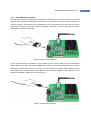
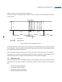
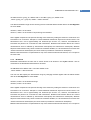
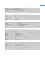
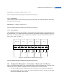
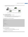
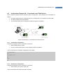
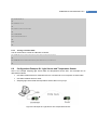
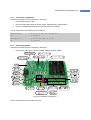
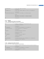
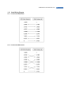
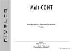
Download Data Sheet

Transcript
ProBee-ZE10 User Guide Rev.1.6.2
ZigBee OEM Module
ProBee-ZE10
User Guide
Sena Technologies, Inc.
Rev 1.6.2
1
ProBee-ZE10 User Guide Rev.1.6.2
ProBee-ZE10 User Guide
Firmware version PTv1.X
Copyright
Copyright 2010 ~ 2012, Sena Technologies, Inc. All rights reserved.
Sena Technologies reserves the right to make changes and improvements to its product without providing
notice.
Trademark
ProBee™ is a trademark of Sena Technologies, Inc.
Windows® is a registered trademark of Microsoft Corporation.
Ethernet® is a registered trademark of XEROX Corporation.
Notice to Users
When a system failure may cause serious consequences, protecting life and property against such
consequences with a backup system or safety device is essential. The user agrees that protection against
consequences resulting from system failure is the user's responsibility.
This device is not approved for life-support or medical systems.
Changes or modifications to this device not explicitly approved by Sena Technologies will void the user's
authority to operate this device.
Technical Support
Sena Technologies, Inc.
210 Yangjae-dong Seocho-gu
Seoul 137-130, Korea
Tel: (+82-2) 576-7362
Fax: (+82-2) 573-7710
Email: [email protected]
Website: http://www.sena.com
2
ProBee-ZE10 User Guide Rev.1.6.2
Revision History
Revision
Date
Name
Description
V1.0.0
2010-09-30
KS Choi
Initial Writing
V1.1.0
2010-10-27
KS Choi
Modification for ZE10 PTv1.2
V1.2.0
2011-08-22
HR Zo
Modification for ZE10 PTv1.3
V1.2.1
2011-09-16
HR Zo
Modification of some typographical errors and
addition of Serial Port Pin Map
V1.2.2
2011-09-29
HR Zo
Modification for ZE10 PTv1.4
- Adding AT+RSSI Command
- Modification of the AT+ESCAN result
V1.5
2012-02-21
Uin Burn
* Modification for ZE10 PTv1.5
- Modification of the ATS11 and flow control default
value
- Adding Frequency Agility
* Modification of Key Features about power and
current
* Modification of default function at Pin Assignment
Table
* Modification of Mechanical Drawings
* Modification of Overview
V1.6
2012-08-20
Uin Burn
* Modification of Mechanical Drawings.
* Modification of ATS55 information.
* Modification of some mistypes.
V1.6.1
2013-04-09
Uin Burn
* Modification of Permit Join and Factory Reset
button information.
- Changes rising edge to falling edge
V1.6.2
2014-03-21
Uin Burn
* Modification for some typographical errors.
- S12 to S21 in section 7.2.2, 7.2.3, and 7.2.5
3
ProBee-ZE10 User Guide Rev.1.6.2
Contents
1
2
INTRODUCTION ..................................................................................................... 11
1.1
About This Document......................................................................................................................... 11
1.2
Overview ............................................................................................................................................. 11
GETTING STARTED ............................................................................................... 13
2.1
3
Hardware Installation..........................................................................................................................13
2.1.1
Development Board Layout........................................................................................................13
2.1.2
Antenna Installation ....................................................................................................................14
2.1.3
Module Installation on the Development Board ........................................................................14
2.1.4
Serial/USB Cable Installation .....................................................................................................15
2.1.5
Powering Development Board ...................................................................................................16
2.1.6
USB Driver Installation................................................................................................................16
2.2
Using Terminal Software for AT Commands .....................................................................................17
2.3
Using ProBee Manager for Configuration.........................................................................................18
2.3.1
Serial Port Open..........................................................................................................................18
2.3.2
Configuration ...............................................................................................................................19
2.3.3
Firmware Update.........................................................................................................................21
ZIGBEE NETWORK CONFIGURATION................................................................. 23
3.1
Setting up ZE10 as a Coordinator .....................................................................................................23
3.1.1
Node Type Selection for Coordinator ........................................................................................24
3.1.2
Channel Mask Configuration for Coordinator ...........................................................................24
3.1.3
PAN ID Configuration for Coordinator .......................................................................................25
3.1.4
Permit Joining..............................................................................................................................25
3.2
Setting up ZE10 as a Router .............................................................................................................26
3.2.1
Node Type Selection for Router .................................................................................................26
3.2.2
Channel Mask Configuration for Router ....................................................................................27
3.2.3
PAN ID Configuration for Router................................................................................................27
3.2.4
Permit Joining..............................................................................................................................27
3.3
Setting up ZE10 as an End-Device ...................................................................................................28
3.4
Setting up ZE10 as a Sleepy End-Device ........................................................................................29
3.5
ZigBee Security ..................................................................................................................................30
3.5.1
Security Level..............................................................................................................................31
3.5.2
Link Key .......................................................................................................................................31
3.5.3
Network Key ................................................................................................................................31
3.5.4
Update Key ..................................................................................................................................31
4
ProBee-ZE10 User Guide Rev.1.6.2
3.6
4
DATA TRANSMISSION........................................................................................... 33
4.1
6
Command Mode .................................................................................................................................33
4.1.1
Unicast .........................................................................................................................................33
4.1.2
Multicast.......................................................................................................................................33
4.1.3
Broadcast ....................................................................................................................................34
4.1.4
Sending Binary Data ...................................................................................................................35
4.1.5
Display Incoming Message ........................................................................................................35
4.2
5
Frequency Agility ................................................................................................................................31
Data Mode...........................................................................................................................................36
4.2.1
Unicast Data Mode .....................................................................................................................36
4.2.2
Multicast Data Mode ...................................................................................................................39
4.2.3
Broadcast Data Mode .................................................................................................................40
DIGITAL AND ANALOG I/O.................................................................................... 43
5.1
GPIO (General Purpose Inputs and Outputs) Configuration ...........................................................43
5.2
I/O Sampling .......................................................................................................................................44
5.2.1
Queried Sampling .......................................................................................................................44
5.2.2
Periodic Sampling .......................................................................................................................46
5.2.3
Change Detection Sampling ......................................................................................................47
5.2.4
GPIO Remote Control.................................................................................................................47
WORKING WITH DEVELOPMENT KIT ................................................................. 48
6.1
Development Kit Contents .................................................................................................................48
6.2
Development Board Features............................................................................................................48
6.3
Development Board Hardware Descriptions ....................................................................................49
6.3.1
Power ...........................................................................................................................................49
6.3.2
RS232 Port ..................................................................................................................................50
6.3.3
USB Port ......................................................................................................................................50
6.3.4
ZE10 GPIO Interface ..................................................................................................................50
6.3.5
LEDs (CR12-19)..........................................................................................................................51
6.3.6
Button Switches (SW10-17) .......................................................................................................51
6.3.7
Variable Resistors (VR1, VR2)...................................................................................................51
6.3.8
Temperature Sensor ...................................................................................................................51
6.3.9
Light Sensor ................................................................................................................................52
6.3.10
Terminal Block .............................................................................................................................52
6.4
Configuration Example #1: 1 Coordinator, 1 Router and 1 End-Device .........................................52
6.4.1
Coordinator Configuration ..........................................................................................................53
6.4.2
Router Configuration...................................................................................................................53
6.4.3
End-device Configuration ...........................................................................................................54
5
ProBee-ZE10 User Guide Rev.1.6.2
6.4.4
6.5
Configuration Example #2: 1 Coordinator and 2 End-Devices .......................................................55
6.5.1
Coordinator Configuration ..........................................................................................................55
6.5.2
End-devices Configuration .........................................................................................................55
6.5.3
Turning on/off the LEDs ..............................................................................................................56
6.6
7
Monitoring the Sensors...............................................................................................................54
Configuration Example #3: Light Sensor and Temperature Sensor ...............................................56
6.6.1
Coordinator Configuration ..........................................................................................................57
6.6.2
Router Configuration...................................................................................................................57
6.6.3
Applying .......................................................................................................................................58
6.6.4
Queried Sampling .......................................................................................................................59
6.6.5
Periodic Sampling – Destination Node ......................................................................................60
6.6.6
Periodic Sampling – Sink Node .................................................................................................61
6.6.7
Data Conversion .........................................................................................................................62
AT COMMAND REFERENCE................................................................................. 64
7.1
Command Line Format ......................................................................................................................64
7.2
Standard AT Commands ....................................................................................................................64
7.2.1
AT .................................................................................................................................................64
7.2.2
ATB ..............................................................................................................................................64
7.2.3
ATD ..............................................................................................................................................64
7.2.4
ATE ..............................................................................................................................................65
7.2.5
ATM ..............................................................................................................................................65
7.2.6
ATO ..............................................................................................................................................65
7.2.7
ATR ..............................................................................................................................................65
7.2.8
ATS ..............................................................................................................................................65
7.2.9
ATZ...............................................................................................................................................65
7.2.10
AT&F ............................................................................................................................................65
7.2.11
+++ ...............................................................................................................................................66
7.3
Node Specific Information ..................................................................................................................66
7.3.1
AT+LONGADDR or AT+LA.........................................................................................................66
7.3.2
AT+SHORTADDR or AT+SA ......................................................................................................66
7.3.3
AT+ADDRDISCOVERY or AT+AD.............................................................................................66
7.3.4
AT+OPCH or AT+OC ..................................................................................................................66
7.3.5
AT+OPPANID or AT+OI ..............................................................................................................67
7.3.6
AT+OPEPID or AT+OE ...............................................................................................................67
7.3.7
AT+VERSION or AT+VR ............................................................................................................67
7.3.8
AT+PRODUCTNAME or AT+PN ................................................................................................67
7.4
Network Specific Parameters ............................................................................................................67
7.4.1
AT+CHMASK or AT+CM.............................................................................................................67
7.4.2
AT+PANID or AT+PI....................................................................................................................68
6
ProBee-ZE10 User Guide Rev.1.6.2
7.4.3
AT+EPID or AT+EI ......................................................................................................................68
7.4.4
AT+GROUPID or AT+GI .............................................................................................................68
7.4.5
AT+POWER or AT+PW ..............................................................................................................68
7.4.6
AT+STACK or AT+ZS .................................................................................................................69
7.4.7
AT+NODENAME or AT+NN .......................................................................................................69
7.5
Network Formation and Join ..............................................................................................................69
7.5.1
AT+ASCAN or AT+AS.................................................................................................................69
7.5.2
AT+ESCAN or AT+ES.................................................................................................................69
7.5.3
AT+DSCAN or AT+DS ................................................................................................................70
7.5.4
AT+RSSI or AT+RS.....................................................................................................................70
7.5.5
AT+NODETYPE or AT+NT .........................................................................................................70
7.5.6
AT+PERMIT or AT+PJ ................................................................................................................71
7.5.7
AT+LEAVE or AT+LV ..................................................................................................................71
7.6
End-device ..........................................................................................................................................71
7.6.1
AT+SLEEP or AT+SM .................................................................................................................71
7.6.2
AT+PARENTLA or AT+PL ..........................................................................................................71
7.6.3
AT+PARENTSA or AT+PS..........................................................................................................71
7.6.4
AT+CHILDTABLE or AT+CT.......................................................................................................71
7.7
Data Transmission and Reception ....................................................................................................72
7.7.1
AT+DESTLA or AT+DL ...............................................................................................................72
7.7.2
AT+DESTGROUPID or AT+DG .................................................................................................72
7.7.3
AT+SINKINFO or AT+SI .............................................................................................................72
7.7.4
AT+MAXPAYLOAD or AT+MP ...................................................................................................72
7.7.5
AT+TRASNSMITMODE or AT+TM ............................................................................................72
7.7.6
AT+UNICAST or AT+UC.............................................................................................................73
7.7.7
AT+MULTICAST or AT+MC........................................................................................................73
7.7.8
AT+BROADCAST or AT+BC ......................................................................................................73
7.7.9
AT+REMOTE or AT+RC .............................................................................................................73
7.8
Security ...............................................................................................................................................73
7.8.1
AT+SECURITY or AT+SE...........................................................................................................73
7.8.2
AT+LINKKEY or AT+LK ..............................................................................................................73
7.8.3
AT+NWKKEY or AT+NK .............................................................................................................74
7.8.4
AT+UPDATEKEY or AT+UK .......................................................................................................74
7.9
UART ...................................................................................................................................................74
7.9.1
AT+BAUDRATE or AT+UB .........................................................................................................74
7.9.2
AT+DATABIT or AT+UD ..............................................................................................................74
7.9.3
AT+PARITY or AT+UP ................................................................................................................75
7.9.4
AT+STOPBIT or AT+US .............................................................................................................75
7.9.5
AT+FLOWCTRL or AT+UF .........................................................................................................75
7.10
GPIO....................................................................................................................................................75
7
ProBee-ZE10 User Guide Rev.1.6.2
7.10.1
AT+GPIO or AT+IO .....................................................................................................................75
7.10.2
AT+DIO ........................................................................................................................................76
7.10.3
AT+AI ...........................................................................................................................................76
7.10.4
AT+ SOURCELA or AT+SL ........................................................................................................76
7.11
8
7.11.1
AT+BOOTLOAD or AT+BL .........................................................................................................76
7.11.2
AT+HELP or AT+HP....................................................................................................................77
AT COMMAND EXAMPLES ................................................................................... 78
8.1
Network configuration ........................................................................................................................78
8.1.1
Coordinator..................................................................................................................................78
8.1.2
Router ..........................................................................................................................................78
8.1.3
End-device ...................................................................................................................................78
8.1.4
Sleepy End-device ......................................................................................................................78
8.1.5
Specifying Network .....................................................................................................................78
8.2
9
Firmware Upload and Help ................................................................................................................76
Data Transmission ..............................................................................................................................79
8.2.1
Command Mode..........................................................................................................................79
8.2.2
Data Mode ...................................................................................................................................80
8.3
Security ...............................................................................................................................................80
8.4
UART Settings ....................................................................................................................................81
8.5
GPIO....................................................................................................................................................81
8.6
Firmware Upload ................................................................................................................................82
8.6.1
Local Node ..................................................................................................................................82
8.6.2
Remote Node ..............................................................................................................................82
8.6.3
Clone............................................................................................................................................82
S-REGISTERS ........................................................................................................ 83
9.1
Display Options...................................................................................................................................83
9.1.1
S11 ...............................................................................................................................................83
9.1.2
S12 ...............................................................................................................................................84
9.1.3
S13 ...............................................................................................................................................84
9.1.4
S14 ...............................................................................................................................................84
9.2
Network Settings ................................................................................................................................84
9.2.1
S21 ...............................................................................................................................................84
9.2.2
S22 ...............................................................................................................................................85
9.2.3
S23 ...............................................................................................................................................85
9.3
Data Transmissions ............................................................................................................................85
9.3.1
S31 ...............................................................................................................................................85
9.3.2
S32 ...............................................................................................................................................85
9.3.3
S33 ...............................................................................................................................................86
8
ProBee-ZE10 User Guide Rev.1.6.2
9.3.4
S34 ...............................................................................................................................................86
9.3.5
S35 ...............................................................................................................................................86
9.3.6
S36 ...............................................................................................................................................87
9.3.7
S37 ...............................................................................................................................................87
9.3.8
S38 ...............................................................................................................................................87
9.3.9
S39 ...............................................................................................................................................87
9.4
GPIO....................................................................................................................................................88
9.4.1
S41 ...............................................................................................................................................88
9.4.2
S42 ...............................................................................................................................................88
9.4.3
S43 ...............................................................................................................................................88
9.4.4
S44 ...............................................................................................................................................88
9.4.5
S45 ...............................................................................................................................................89
9.5
End-Device..........................................................................................................................................89
9.5.1
S51 ...............................................................................................................................................89
9.5.2
S52 ...............................................................................................................................................89
9.5.3
S53 ...............................................................................................................................................90
9.5.4
S54 ...............................................................................................................................................90
9.5.5
S55 ...............................................................................................................................................90
9.5.6
S56 ...............................................................................................................................................90
9.6
Sink ......................................................................................................................................................91
9.6.1
S61 ...............................................................................................................................................91
9.6.2
S62 ...............................................................................................................................................91
10
PIN ASSIGNMENTS ............................................................................................ 92
11
CONNECTIONS ................................................................................................... 94
11.1
Serial Port Pin Outs ............................................................................................................................94
11.2
Serial Wiring Diagram ........................................................................................................................95
11.2.1
To Host with DTE Interface ........................................................................................................95
11.2.2
To Host with DCE Interface ........................................................................................................95
12
MECHANICAL DRAWINGS................................................................................. 96
13
WARRANTY......................................................................................................... 97
13.1
GENERAL WARRANTY POLICY......................................................................................................97
13.2
LIMITATION OF LIABILITY ................................................................................................................97
13.3
HARDWARE PRODUCT WARRANTY DETAILS ............................................................................98
13.4
SOFTWARE PRODUCT WARRANTY DETAILS .............................................................................98
13.5
THIRD-PARTY SOFTWARE PRODUCT WARRANTY DETAILS ...................................................98
14
14.1
REGULATORY INFORMATION ........................................................................... 99
FCC .....................................................................................................................................................99
9
ProBee-ZE10 User Guide Rev.1.6.2
14.2
CE ......................................................................................................................................................100
14.3
TELEC ...............................................................................................................................................100
14.4
KCC ...................................................................................................................................................100
14.5
ZigBee Alliance .................................................................................................................................100
15
RF INFORMATION............................................................................................. 101
10
ProBee-ZE10 User Guide Rev.1.6.2
1
Introduction
1.1
About This Document
This document provides an introduction on configuration and operation of the ProBee-ZE10 ZigBee OEM
module. This document assumes the user is using the ZE10 starter kit for evaluation hence the pictures
and configuration examples shown in this document are all based on the ZE10 starter kit.
This document does not provide full detail of the hardware specifications. Please refer to the ProBeeZE10 data sheet for further references on the hardware design.
1.2
Overview
The ProBee-ZE10 is an all-in-one ZigBee OEM module with integrated ZigBee core and radio/antenna
circuits together with high level software library. Using the ZE10, OEM manufacturers can easily and costeffectively integrate ZigBee functionality into target products in timely manner.
The ZE10 OEM module is designed to meet specific requirements of low cost and low power wireless
applications such as Home Automation, Smart Energy, Health care, Building Automation and Telecom
Services by adopting the ZigBee technology. The ZE10 is based on the Ember EM250 ZigBee core and
certified ZigBee Alliance based on ZigBee 2007 and ZigBee Pro stack.
Despite of its low cost and low power consumptions, the ZE10 provides high performance and robust data
transfer capability for wide range of applications. The ZE10 can transfer data at up to 250 kbps and reach
up to 1.6 km (1 mile) outdoor line-of-sight.
Key Features

Integrated 2.4GHz, IEEE 802.15.4-compliant transceiver

ZigBee 2007/ ZigBee Pro stack

ZigBee core: Ember EM250

Transmit Power: +20dBm E.I.R.P (max.)

Receiver Sensitivity: -102dBm @1% BER

Supply Voltage: 2.7~3.6 VDC

TX Current: 190mA @3.3V (max.)

RX Current: 45mA @3.3V (max.)

Sleep Current: ≤ 2uA

Working Distance: 1.6 km ( 1 mile)

Various Antenna/Connector Options: Dipole 1/3/5dBi, U.FL, Chip

UART Signals Support: UART_TXD/RXD, RTS/CTS, DTR/DSR

4 Analog Inputs

13 Digital Inputs/Outputs
11
ProBee-ZE10 User Guide Rev.1.6.2

RoHS Compliant
Applications

Advanced Metering Infrastructure

Home Area Networks (HAN)

Neighborhood Area Networks (NAN)

Home Automation

Advanced lighting, entertainment and climate control systems

Service-based monitoring, security and awareness systems

Commercial Building Automation

Climate & lighting control systems

Industrial and Domestic Applications
12
ProBee-ZE10 User Guide Rev.1.6.2
2
Getting Started
Creating a ZigBee network using the ZE10 modules consists of the following steps:

Install the ZE10 module on the development board

Create a ZigBee network by configuring a ZE10 module as the coordinator

Configure ZE10 modules as routers. This step is optional since the coordinator works as a router
too.

Configure ZE10 modules as end-devices

Transmit data between ZE10 devices
This chapter describes how to install the ZE10 modules on to the development boards and how to use
terminal software programs to access the ZE10 modules using AT commands for configurations and
operations. The rest of the steps including ZigBee network creation, coordinator/router/end-device
configurations and data transmissions are described in the following chapters. The more detailed
information on the starter kit and the configuration examples are also provided in the later chapter.
2.1
Hardware Installation
2.1.1
Development Board Layout
Figure 2-1 shows the layout of the development board. The development board provides the interface
between the ZE10 and the external serial port or USB port together with input/output terminals for
convenient tests.
Figure 2-1 Development Board Layout
13
ProBee-ZE10 User Guide Rev.1.6.2
2.1.2
Antenna Installation
The ZE10 starter kit includes the several antennas for evaluation purposes. You can try different antennas
for testing purpose and select the appropriate antenna for the actual applications. Figure 2-2 shows how
to install the RP-SMA dipole antenna to the ZE10 module.
Figure 2-2 RP-SMA Dipole Antenna Installation
2.1.3
Module Installation on the Development Board
Once the antenna is installed on the ZE10 module, the ZE10 module can be installed on the development
board.
Figure 2-3 ZE10 Installation on the Development Board
14
ProBee-ZE10 User Guide Rev.1.6.2
2.1.4
Serial/USB Cable Installation
After the ZE10 is securely installed on the development board, please connect the included serial cable
between the development board and your computer so AT commands can be sent from the computer to
the ZE10 module. The serial port of the development board is DB9 female as a DTE terminal, and the
serial cable included is a cross-over cable for DTE-DTE connection. To use the serial port, the HOST
(SW2) switch should be set to UART.
Figure 2-4 Serial Cable Installation
In case the serial port is not available for the computer, you can use the USB port of the development
board instead. In this case, the internal USB-RS232 converter of the development board will convert the
USB signal to the RS232 signal and vice versa. To use the USB port, the HOST (SW2) switch should be
set to USB and the software driver for the USB in the CD should be installed on the computer. For the
USB driver installation, please refer to the section 2.1.6.
Figure 2-5 USB Cable Installation
15
ProBee-ZE10 User Guide Rev.1.6.2
2.1.5
Powering Development Board
Once all the installations are completed, please plug in the power connector using the included DC power
adapter. The RS_PWR, USB_PWR and BATT_EN jumpers should be all OPEN to use the DC power
adapter. Alternatively, the development board can be powered using batteries, or from the USB port or
through the RS232 port pin 9. In these cases, the power source jumpers should be set accordingly. For
details about the power source jumper settings, please refer to the section 6.3.1 Power.
Figure 2-6 Plugging DC Power Adapter
2.1.6
USB Driver Installation
In case the USB interface is used for the communication between the development board and the
computer, the corresponding software driver needs to be installed on the computer. Windows XP and later
versions already include the USB driver. When Windows asks for the location of the USB driver, you can
select the option to “install the software automatically” as shown in Figure 2-7. You can also choose to
install the driver from the CD included if the driver is not installed correctly for some reason.
Figure 2-7 USB Driver Installation
16
ProBee-ZE10 User Guide Rev.1.6.2
2.2
Using Terminal Software for AT Commands
Once the hardware installation is complete, the ZE10 unit is ready to communicate with the computer
using the AT commands using a terminal emulation software. You can use any kind of terminal emulation
software. This document assumes HyperTerminal is used. If you are using Windows Vista or 7,
HyperTerminal is no longer included in the Windows so you need to download HyperTerminal from the
Internet. For more details on HyperTerminal, please refer to Microsoft web page.
Once the HyperTerminal is installed, launch HyperTerminal and select the serial port that is connected to
the ZE10 development board and enter the serial settings to use. The default serial settings of the ZE10
are 9600 bps, 8 data bit, none parity, 1 stop bit, none flow control.
Figure 2-8 HyperTerminal Serial Settings
To display the AT commands that are being typed, you need to enable the local echo option on the
HyperTerminal. To enable this option, Go to File->Properties->Settings->ASCII setup and select the
“Echo typed characters locally” option. To verify the connection, type AT and press the Enter key. If the
AT command is accepted by the ZE10, OK string will be displayed on the screen.
17
ProBee-ZE10 User Guide Rev.1.6.2
Figure 2-9 Testing AT Command on HyperTerminal
2.3
Using ProBee Manager for Configuration
It is possible to set or get the configurations of the ZE10 using ProBee Manager. This PC utility helps that
a user can configure several setting values of local node and remote node easily without a terminal
program. It is possible to export current configuration and import it to other nodes. It is also possible to
restore to factory default configuration.
It provides users with functions to upgrade firmware of not only local node but also remote node and
clone the firmware of local node to remote node.
2.3.1
Serial Port Open
Figure 2-10 ProBee Manager Serial Port Open
To connect to local node through serial port, please follow the steps as below:

Set ‘Serial Port’ properties corresponding to the UART configuration of local node.

Click ‘Open’ button.
18
ProBee-ZE10 User Guide Rev.1.6.2
ProBee manager displays the main window like Figure 2-11 after connecting to local node.
Figure 2-11 ProBee Manager Main Window
Clicking ‘Reboot’ button reboots the local node. Users can reload and refresh the recent configuration of
the local node at ProBee manager by clicking ‘Reload’ button. ‘Configuration’ tab and ‘Firmware Update’
tab can help move to the ‘Configuration’ screen and the ‘Firmware Upgrade’ screen.
2.3.2
Configuration
The Configuration Pane appears when the ‘Configuration’ tab is selected.
To change configuration, users need to find and modify the property and then apply changes. The
properties are categorized according to the function. Selecting a category unfolds or folds the property list.
The name, the current value and the description of the property are shown at the right of the configuration
pane by selecting a property in the property list. It is possible to edit and save the current value of editable
19
ProBee-ZE10 User Guide Rev.1.6.2
property. Whenever property is modified, it is necessary to save the change by clicking the ‘Save’ button
in order not lose it moving to other properties. To apply changes, please reboot the device by clicking
‘Reboot’ button. The ‘Save’ button is disabled for read-only property.
Figure 2-12 ProBee Manager Configuration Pane
In Figure 2-12, the ‘Node Information’ category is selected and the ‘IEEE Address’ property is selected, so
Its description is displayed. The ‘Save’ button is disabled because the ‘IEEE Address’ property is readonly.
The configurations of the remote nodes joining the network where the local node belongs can be modified,
too. Because a sleepy end-device often enters sleep mode, to remote configuration from a sleepy enddevice may not work.
To connect to local node through serial port, please follow the steps as below:

Click the ‘…’ button at ‘Remote Configuration’ section.

Scan the remote nodes joining the network and select the remote node to configure, that results
in displaying the remote node in the ‘Address’ edit box.

Check the ‘Remote Device Setting’ check box and the caption of the ‘Restore to Factory Default’
button at the ‘Configuration Management’ section becomes ‘Reboot’ that makes the remote node
reboot and configuration of the selected node is displayed.
20
ProBee-ZE10 User Guide Rev.1.6.2

Select and modify the property.

Click the ‘Save’ button.

Click the ‘Reboot’ button whose caption used to be ‘Restore to Factory Default’ to apply changes.
To export the configuration, please follow the steps as below:

Click the ‘Export’ button at the ‘Configuration Management’ section and the ‘Save As’ dialog pops
up.

Select the path and enter the file name to store the configuration at.

Click the ‘Save’ button’ and the configuration is exported to the designated file.
Exported file can be used at other devices by importing them. The configuration of remote node can be
exported and imported by checking the ‘Remote Device Setting’ check box.
Users can reset to factory default by clicking the ‘Restore to Factory Default’ at the ‘Configuration
Management’ section.
2.3.3
Firmware Update
Figure 2-13 ProBee Manager Firmware Update Pane
The Firmware Update Pane appears when the ‘Firmware Update’ tab is selected. The ‘Message’ section
displays informative message about the progress of updating firmware.
21
ProBee-ZE10 User Guide Rev.1.6.2
To update firmware at local node, please follow the steps as below:

Select a firmware file to update at the ‘Firmware Update’ section. The ‘Choose file in local PC’
button pops up the dialog where users can select the firmware file at local PC and the ‘Download
from web server’ button helps users download the firmware from web server.

Click the ‘Update’ button at the ‘Device Update’ section to update the local node. The progress
rate is expressed at the ‘Local Device Update’ section and informative messages are shown at
‘Message’ section.
ProBee Manager also supports to update the firmware of remote nodes which join the network where
local node is. Because a sleepy end-device often enters sleep mode, to update remote node from a
sleepy end-device may not work.
To update firmware at remote node, please follow the steps as below:

Select a firmware file.

Click the ‘Search’ button, that scans the remote nodes joining the network where local node
belongs.

Select the remote nodes to update in the remote nodes list.

Click the ‘Update’ button at the ‘Remote Device Update’ section.
It is also possible to copy the firmware of local node to remote nodes by checking the ‘Clone local
firmware’ check box and clicking the ‘Update’ button at the ‘Remote Device Update’ section.
22
ProBee-ZE10 User Guide Rev.1.6.2
3
ZigBee Network Configuration
A ZigBee Network consists of a coordinator, routers and end-devices. A minimal ZigBee network consists
of one coordinator and multiple end-devices which directly connect to the coordinator. For larger ZigBee
networks, routers are required to provide redundant routings to form mesh networks.

ZigBee Coordinator: The coordinator forms the root of the network tree and might bridge to
other networks. There is exactly one ZigBee coordinator in each network since the coordinator
starts the ZigBee network itself. It also stores information about the network, including acting as
the Trust Center & repository for security keys.

ZigBee Router: The routers are able to route messages between other devices. Since the
coordinator provides the routing functionality too, the routers are optional to form a ZigBee
network.

ZigBee End-Device: The end-device contains just enough functionality to talk to the parent node
which is either the coordinator or a router. It cannot relay data from other devices.

ZigBee Sleepy End-Device: The sleepy end-device is the same with normal end-device except it
can stay in the sleep mode much longer. This relationship allows the end-device to sleep
significant amount of the time and achieve the long battery life.
The ZE10 can be configured to work either as a coordinator, a router, an end-device or a sleepy enddevice. Once the operation mode of the ZE10 is selected, corresponding parameters need to be set up
appropriately. This chapter explains how to configure the ZE10 operation mode and other parameters
related to the ZigBee network itself.
Table 3-1 ZigBee Node Types
Node Type
Recommendation when to use ZE10
Coordinator
It should be selected when it is first time to establish the network.
Router
It is recommended when there is a network already and it needs to be expanded. A
router is suitable for fast and stable data transmissions and receptions.
End-Device
It is recommended when it doesn’t need to expand the network anymore and there
are enough nodes as parents. An end-device consumes less power than a router.
Sleepy End-Device
It is recommended when the data transmissions occur rarely and in very small
quantities. A sleepy end-device can lose data if sleep duration is too long, but it is
possible to consume extremely low power as low as 2uA.
3.1
Setting up ZE10 as a Coordinator
A coordinator relays messages and can act as a parent to other nodes. Every personal area network
(PAN) must be started by a node acting as the coordinator. In general, this device is always powered on.
To set up the ZE10 to work as the coordinator, please follow the steps as below
23
ProBee-ZE10 User Guide Rev.1.6.2

Configure the ZE10 node type as the coordinator

Optionally, select the channel mask. Otherwise, the ZE10 will use the default channel mask.

Optionally, set up the PAN ID and/or the extended PAN ID. Otherwise, the ZE10 will generate the
PAN ID and/or the extended PAN ID automatically.

3.1.1
Permit joining when other router or end-device tries to join the ZigBee network.
Node Type Selection for Coordinator
The ZE10 module can be configured as a ZigBee coordinator by the AT command as below:
AT+NODETYPE=n or AT+NT=n
, where n is 0 = none, 1 = coordinator, 2 = router, 3 = end-device, 4 = sleepy end-device
After the operation mode is selected, ATZ command should be performed to reset the unit to have the
change applied.
Example)
AT+NODETYPE=1<CR>
# Set node type as the coordinator
OK<CR>
# Response
ATZ<CR>
# Apply the change
OK<CR>
# Response
3.1.2
Channel Mask Configuration for Coordinator
When the ZigBee coordinator starts, it scans predefined frequency channels to find the best frequency
channel to use without causing interference with other wireless devices. The user is able to specify the
channels to use with the AT command as below:
AT+CHMASK=n or AT+CM=n
, where n = channel mask to use. Default = 0x03FFF000
This value has a 32-bit hexadecimal unsigned integer. Each bit represents whether a channel will be used
or not. For example, to use a channel between 12 and 15, the 12, 13, 14 and 15 bits of the channel mask
should be 1 and all other bits should be 0. The default setting is 0x3FFF000 which means that all the
channels from 12 to 25 can be used. The ZE10 supports only the channels between 12 and 25, so 0~11
bits and 26~31 bits should be 0. Table 3-2 shows the bit mask for each channel.
24
ProBee-ZE10 User Guide Rev.1.6.2
Table 3-2 Channel Bitmask
Channel
12
13
14
15
16
17
18
Bit mask
00001000
00002000
00004000
00008000
00010000
00020000
00040000
Channel
19
20
21
22
23
24
25
Bit mask
00080000
00100000
00200000
00400000
00800000
01000000
02000000
3.1.3
PAN ID Configuration for Coordinator
Every ZigBee network should be assigned a PAN ID to identify the network. If the PAN ID is 0000, the
ZE10 will generate a random 16-bit PAN ID to start the ZigBee network. Otherwise, the user can enter the
PAN ID using the AT command as below:
AT+PANID=xxxx or AT+PI=xxxx
, where xxxx is PAN ID to use. For example, 12AB. Default setting is 0000
When choosing a PAN ID, the user needs to make sure that there is no ZigBee network using the same
PAN ID. If the PAN ID is already used by another ZigBee network, the PAN ID is unavailable and the user
should choose a new PAN ID. In order to avoid this, PAN ID auto-generation is strongly recommended.
The user can also assign the 64-bit extended PAN ID to the ZE10 using the AT command below. If the
extended PAN ID is 0000000000000000, the ZE10 uses its IEEE address as the extended PAN ID. The
extended PAN ID cannot be shared with other ZigBee networks, either.
AT+EPID=xxx…xxx or AT+EI= xxx…xxx
, where xxx…xxx is EPID to use. For example, 0123456789ABCDEF. Default setting is 000…000.
3.1.4
Permit Joining
When a router or an end-device tries to join the ZigBee network, there should be at least one coordinator
or router which is permitting joining. If there is no router in the ZigBee network yet, the coordinator should
permit joining. The ZE10 provides three ways to permit joining are as follows:

Permanently permitting by configuration

Transiently permitting by AT command

Transiently permitting by digital input signal
If joining is permanently permitted, any device can join anytime. Since this will allow even an unidentified
device to join the network anytime, this mode should be selected with extra caution. The AT command to
permit joining permanently is as follows:
AT+PERMIT=255 or AT+PJ=255
25
ProBee-ZE10 User Guide Rev.1.6.2
The user can permit joining for a moment at need. The AT command to permit joining is
AT+PERMIT=n or AT+PJ=n
, where n is the duration to permit in seconds ranging 1~254 seconds.
The user can also configure the ZE10 to permit joining when the digital input GPIO0 is active. The AT
command to enable this functionality is as follows:
AT+GPIO0=5 or AT+IO0=5
When the ZE10 detects falling edge of the GPIO0, the ZE10 permits joining for the duration that is
configured in S-register 22 (S22). The AT command to change the duration is as follows:
ATS22=n
, where n is the duration to permit in seconds ranging 1~254 seconds. Default is 255.
S22 value determines the time that the device will allow other devices to join to it. If set to 255, the device
will always permit other nodes joining. If the user reboots the coordinator (or a router), the device allows
other nodes to join the network for the period defined by S-register 22.
Note: When a device that has joined a network reboots, the device is able to join the network regardless
of permitting. But, after the device has joined other network, rejoining the previous network should be
permitted by the coordinator or a router.
3.2
Setting up ZE10 as a Router
A router is a full-function routing device that relays messages and can act as a parent to other nodes.
These devices must be always powered on.
To configure the ZE10 as a ZigBee router, please follow the steps below.

Configure the ZE10 node type as a router.

Optionally, select the channel mask. Otherwise, the ZE10 will use the default channel mask.

Optionally, set up the PAN ID and/or the extended PAN ID. Otherwise, the ZE10 will scan and join
the ZigBee network found automatically.

3.2.1
Permit joining when other router or end-device tries to join the ZigBee network.
Node Type Selection for Router
The ZE10 module can be configured as a ZigBee router by the AT command as below:
AT+NODETYPE=n or AT+NT=n
, where n is 0 = none, 1 = coordinator, 2 = router, 3 = end-device, 4 = sleepy end-device
26
ProBee-ZE10 User Guide Rev.1.6.2
After the operation mode is selected, ATZ command should be performed to reset the unit to have the
change applied.
Example)
AT+NODETYPE=2<CR>
# Select router mode
OK<CR>
# Response
ATZ<CR>
# Apply the change
OK<CR>
# Response
3.2.2
Channel Mask Configuration for Router
When the ZE10 as a ZigBee router or a ZigBee end-device tries to join, it scans all the channels
configured by channel mask to find the ZigBee network to join. The channel mask of router or end-device
should include the channel on which the coordinator is operating. On the assumption that the coordinator
of the network to join is operating on channel 12, the router or end-device trying to join should have a
channel mask of which 12th bit is 1.
3.2.3
PAN ID Configuration for Router
The PAN ID of a ZigBee router or a ZigBee end-device should be the same with the PAN ID of the ZigBee
coordinator. If the coordinator is using a randomly generated PAN ID, the user can get the operating PAN
ID by running the AT command below on the coordinator:
AT+OPPANID or AT+OI
If the PAN ID of a ZigBee router or a ZigBee end-device is 0000, the PAN ID is ignored. After checking the
PAN ID, the ZE10 trying to join compares the extended PAN ID to make sure whether the network is the
right network to join. If the extended PAN ID is the same with its configured extended PAN ID, it will try to
join the network. Otherwise, it will try to find another network. The user can get the operating extended
PAN ID by running the AT command below on the coordinator:
AT+OPEPID or AT+OE
If the extended PAN ID of a ZigBee router or a ZigBee end-device is 0000000000000000, the extended
PAN ID is ignored
3.2.4
Permit Joining
The ZigBee router is configured and works the same way with the coordinator to permit joining of other
nodes. Please refer to the section 3.1.4 Permit Joining for the configuration.
27
ProBee-ZE10 User Guide Rev.1.6.2
3.3
Setting up ZE10 as an End-Device
An end-device is a leaf node which communicates only with its parent node and will not relay messages
directly. To configure the ZE10 as a ZigBee end-device, please follow the steps below.

Configure the ZE10 node type as an end-device

Optionally, select the channel mask. Otherwise, the ZE10 will use the default channel mask.

Optionally, set up the PAN ID and/or the extended PAN ID. Otherwise, the ZE10 will scan and join
the ZigBee network found automatically.

Configure the poll timeout and the poll period
Please refer to the section 3.2 Setting up ZE10 as a Router for the AT commands regarding the node
type selection, the channel mask configuration and the PAN ID/Extended PAN ID configuration.
When an end-device joins the network, the power LED blinks periodically if GPIO1 is set to specific
functionality. The end-device belongs to a parent node which is either the coordinator or a router, and the
parent node registers the end-device to its internal child table for message relaying. This table is
maintained as long as the end-device polls the parent node periodically within the poll timeout value of the
parent node. If the end-device does not poll for the poll timeout value of the parent node, the parent node
removes the end-device from its child table and does not relay the message any more. Hence, the poll
period of the end-device should be equal or shorter than the poll timeout of the parent node to avoid
accidental removal of the end-device from the parent node’s child table.
The ZE10 poll interval can be configured by setting the S-registers using the AT commands as below.
ATS51=n, where n is poll timeout in seconds and the default is 60.
This value is for a parent node. If an end-device does not send a poll request to its parent coordinator or
router within the poll timeout, the end-device is removed from the child table.
ATS56=n, where n is poll period in seconds and the default is 5.
End-device polls the parent node at poll period defined by S56 periodically. It is for the connection to the
parent node and data transmission with other nodes in the network.
ATS55=n, where n is rejoin timeout and the default is 10.
When the connection to the parent node is broken for S55 in seconds, the child node tries to rejoin the
current network.
Even though the end-device needs to poll the parent node continuously, it does not go into the sleep
mode and it can send and receive messages any time unlike the sleepy end-device.
28
ProBee-ZE10 User Guide Rev.1.6.2
3.4
Setting up ZE10 as a Sleepy End-Device
A sleepy end-device can turn off radio to save power. To configure the ZE10 as a ZigBee sleepy enddevice, please follow the steps below.

Configure the ZE10 node as a sleepy end-device.

Optionally, select the channel mask. Otherwise, the ZE10 will use the default channel mask.

Optionally, set up the PAN ID and/or the extended PAN ID. Otherwise, the ZE10 will scan and join
the ZigBee network found automatically.

Configure the settings for sleep interval.
Please refer to the section 3.2 Setting up ZE10 as a Router for the AT commands regarding the node
type selection, the channel mask configuration and the PAN ID/Extended PAN ID configuration.
One of the unique features of the ZigBee device is its extreme low power consumption which is mainly
achieved by its efficient sleep and wake-up mechanism. While ZigBee coordinator and routers are
required to be in operation all the time, ZigBee sleepy end-devices can be configured to be in the sleep
mode most of the time and only wake up at pre-configured time interval for data transmission before it
goes into the sleep mode again. The ZE10 sleep interval can be configured by setting the S-registers
using the AT commands as below.
ATS51=n, where n is poll timeout in seconds and the default is 60.
This value is for a parent node. If a sleepy end-device does not send a poll request to its parent
coordinator or router within the poll timeout, the sleepy end-device is removed from the child table.
Unlike the non-sleepy end-device, sleepy end-device does not use S56 as the poll period. Instead, it uses
S53 as the sleep duration which works similar to the poll period, except it goes to sleep mode.
ATS53=n, where n is sleep duration in quarter seconds and the default is 8.
The ZE10 sleeps for sleep duration and turns off radio.
ATS52=n, where n is poll period in milliseconds and the default is 100.
Sleepy end-device wakes up from the sleep mode if S53 timer expires or GPIO0 interrupt is generated or
serial data is received. Once the sleepy end-device wakes up, it polls the parent node at poll period
defined by S52 until it goes to sleep mode again. Since the sleepy end-device exchanges data with the
parent node only by polling, S52 poll period is usually configured as around 100 ms.
ATS54=n, where n is standby timeout in seconds and the default is 5.
If there is no RF data or serial data for S54 seconds, the sleepy end-device goes to sleep mode again. If
any serial or RF data is sent or received, the timer will reset and the sleepy end-device waits for another
S54 seconds before it goes to sleep mode again.
29
ProBee-ZE10 User Guide Rev.1.6.2
ATS55=n, where n is rejoin timeout and the default is 10.
When the connection to the parent node is broken for S55 in seconds, the child node tries to rejoin the
current network.
Parent Node
S54
S52
S53
Sleep
Wake-Up
Sleep
Sleepy End-Device
Poll Request
Data Exchange
Figure 3-1 Sleep Interval and Wake-up Timing
The sleepy end-device can also wake up from the sleep mode by GPIO0 interrupt or incoming serial data.
Once it wakes up, it also polls with the parent node at S52 interval and goes into sleep mode after S54
time elapses after the last data exchange.
Note: If the sleepy end-device wakes up by incoming serial data, the integrity of the first incoming byte is
not guaranteed. It is strongly recommended to wake up the sleepy end-device by using GPIO0 first before
sending the serial data or use higher level serial data protocol to check the data integrity.
3.5
ZigBee Security
Security is a major concern in the ZigBee architecture. Although ZigBee uses the basic security elements
in IEEE 802.15.4 (e.g., AES encryption & CCM security modes), the ZE10 increases the security level
with:

128 bit AES encryption algorithms

Strong, NIST-approved security

Defined Key Types (Link, Network)

Defined Key setup and maintenance
30
ProBee-ZE10 User Guide Rev.1.6.2

CCM (Unified/Simpler mode of operation)

Trust Centers
3.5.1
Security Level
In order to use security in the application, a user should set security level using the AT command below.
Set 1 defines both Authentication and Encryption at the network layer. Set 0 defines no security. Disabling
security in the application is not ZigBee compliant. All nodes in the network should have the same
security level setup. The security level is configured using the AT command below.
AT+SECURITY=n or AT+SE=n, where n is encryption level. (0=disable, 1=enable)
3.5.2
Link Key
The trust center (normally coordinator in network) requests link key before a device is trying to join
network. If link key the device has is wrong, joining process will be denied. Hence, all nodes in the
network should have the same link key setup before joining the network.
AT+LINKKEY=xxx…xxx or AT+LK= xxx…xxx, where xxx…xxx is 128-bit hexadecimal trust center link key.
Default is FFF…FF.
3.5.3
Network Key
It is the network-wide key used to secure transmissions at the Network Layer. The network key encrypts
all transmissions at the Network Layer. The network key only needs to be set up for the coordinator.
AT+NWKKEY=xxx …xxx or AT+NK=xxx…xxx, where xxx …xxx is 128-bit hexadecimal network key.
Default is FFF…FF.
3.5.4
Update Key
A trust center can update the Network Key to help minimize the risk associated with a particular instance
of the network key being compromised. Key updates are broadcast by the trust center throughout the
network, encrypted using the current network key. Devices that hear the broadcast will not immediately
use the key, but simply store it. Later, a key switch is broadcast by the trust center to tell all nodes to start
using the new key. At a minimum, the trust center should allow adequate time for the broadcast of the
new key to propagate throughout the network before switching.
AT+UPDATEKEY<CR> or AT+UK<CR>
3.6
Frequency Agility
Frequency Agility refers to the function to shift operating channel to avoid interference. To perform the
frequency agility function, the network manager monitors communication failures, decides to changes the
operating channel and send message to indicate the channel change. Other nodes in the network move
31
ProBee-ZE10 User Guide Rev.1.6.2
to the designated channel by responding to the message.
Even though ZE10 cannot be a network manager, ZE10 implements the frequency agility function by
responding to the message to indicate the channel change by the network manager. Because ProBeeZE20S can be a network manager when it is set to coordinator and its frequency agility function is
enabled, ZE10 with ProBee-ZE20S can compose the ZigBee network implementing the frequency agility.
32
ProBee-ZE10 User Guide Rev.1.6.2
4
Data Transmission
The ZE10 supports three different types of data transmissions: unicast, multicast and broadcast. Unicast
is to transmit data to a specific ZigBee device. Multicast is to transmit data to a group of ZigBee devices
that are assigned a specific group ID. Broadcast is to transmit data to all ZigBee devices (or specific type
of ZigBee nodes if specified) in the network.
ZE10 has such operation modes as command mode and data mode. Data can be transmitted at each
operation mode as below:

Command mode: Because this mode is for entering commands to set and manage a ZE10, as
many data as allowed are transmitted at a time by using AT command.

Data mode: Because this mode is for transmitting data, it is possible to send data consecutively.
“+++” changes the operation mode from the data mode to command mode.
4.1
Command Mode
4.1.1
Unicast
Unicast transmissions are sent from a source device to a destination device. The destination device can
be any ZigBee device in the ZigBee network. To specify the destination device, the ZigBee address of the
destination device should be known.
There are two different ZigBee addresses assigned to each ZigBee device. The 64-bit address is a
unique device address assigned during manufacturing. The 64-bit address is also called IEEE address or
extended address. The 16-bit address is assigned to the device when it joins a ZigBee network. The
ZE10 can send unicast messages based on either 16-bit address or 64-bit address. The AT command for
the unicast transmissions is as below:
AT+UNICAST=<node_id>,<MSG><CR> or AT+UC=<node_id>,<MSG><CR>
, where <node_id> = 16-bit or 64-bit address, <MSG> = data to transmit
The maximum payload of the message is 90 bytes (or 72 bytes under security enabled). If the message
length exceeds the maximum payload, the message cannot transmit and the error message will be
presented. The AT command to get the maximum payload is as below:
AT+MAXPAYLOAD?<CR> or AT+MP?<CR>
4.1.2
Multicast
Multicast transmissions are sent from a source device to destination devices with the specific group ID.
The group ID is assigned to the devices using the AT+GROUPID command. The AT command for the
multicast transmissions is as below.
33
ProBee-ZE10 User Guide Rev.1.6.2
AT+MULTICAST=<group_id>,<MSG><CR> or AT+MC=<group_id>,<MSG><CR>
, where <group_id> = group ID, <MSG> = data to transmit
The data transmission range can be set using the AT commands below. Please refer to the 9 S-Registers
for more details.
ATS36=n, where n is the radius.
ATS37=n, where n is the number of hops through nonmembers.
Note: ZigBee compliance rules prevents flooding of the network by limiting the network to a maximum of 9
broadcasts over 8 seconds. Attempts to submit additional broadcasts beyond this should result in the
transmission error. This is approximately one broadcast per second. It is, however, recommended to
broadcast one packet over 2 seconds for safe transmission. Broadcast transmission failure also causes
retransmission which is affected by transmission timeout(S33) and transmission retries(S32). Because
frequent retransmissions may cause to break the broadcast limitation, it is recommended to set more than
1000 for transmission timeout(S33) and set as small as possible for transmission retries(S32) .
Multicast data transmission is implemented on top of the network broadcast mechanism, so it is subject to
the same rules.
4.1.3
Broadcast
Broadcast transmissions are sent from a source device to all devices in the ZigBee network. The AT
command for the broadcast transmissions is as below.
AT+BROADCAST=<MSG><CR> or AT+BC=<MSG><CR>
, where <MSG> = data to transmit
The user can also specify the transmission range by changing the S35 register value as below. Please
refer to the 9 S-Registers for more details.
ATS35=n, where n is the broadcast range.
ATS36=n, where n is the radius.
Note: ZigBee compliance rules prevents flooding of the network by limiting the network to a maximum of 9
broadcasts over 8 seconds. Attempts to submit additional broadcasts beyond this should result in the
transmission error. This is approximately one broadcast per second. It is, however, recommended to
broadcast one packet over 2 seconds for safe transmission. Broadcast transmission failure also causes
retransmission which is affected by transmission timeout(S33) and transmission retries(S32). Because
frequent retransmissions may cause to break the broadcast limitation, it is recommended to set more than
1000 for transmission timeout(S33) and set as small as possible for transmission retries(S32).
Multicast data transmission is implemented on top of the network broadcast mechanism, so it is subject to
34
ProBee-ZE10 User Guide Rev.1.6.2
the same rules.
4.1.4
Sending Binary Data
Because some characters like carriage return, line feed and back space collides with AT commands in
command mode and back slash(‘\’) is used for control character for binary encoding, they cannot be
transmitted as they are. The characters out of range between 0x20(Space) and 0x7E(‘~’) in hexadecimal
are not expressed at the AT commands for transmitting data. In order to transmit these characters in
command mode, these characters must be encoded in a command line. The examples of special
characters encoding are shown in Table 4-1.
Table 4-1 Examples of Special Characters Encoding
HEX
Abbreviation Glyph
Encoded
Description
00
NULL
-
\00
Null character
0D
CR
-
\0D
Carriage return
0A
LF
-
\0A
Line feed
08
BS
-
\08
Backspace
09
HT
-
\09
Horizontal Tab
7F
DEL
-
\7F
Delete
5C
-
\
\5C
Control character for binary encoding
For example, when sending abc<CR> with AT+BROADCAST command, the command should be as
follows:
AT+BROADCAST=abc\0D<CR>
4.1.5
Display Incoming Message
S11 register determines whether incoming message will be shown or not in the command mode. In the
data mode, on the other hand, incoming data is always displayed. To change the S11 register, please use
the AT command as below:
ATS11=<value><CR>
, where <value> = 0 to hide incoming message, 1 to show incoming message.
If user wants to display incoming message in command mode, S11 should be enabled. It is displayed by
the form of +<IEEE address>|<MSG><CR>.
When displaying incoming messages in command mode, some characters are encoded in the same way
with sending binary data as in Table 4-1. For example,when receiving abc<CR> from 0001950000000001,
the displaying message is as follows:
35
ProBee-ZE10 User Guide Rev.1.6.2
+0001950000000001| abc\0D<CR>
Note: In PTv1.2 or earlier version, only the characters mentioned at Table 4-1 are encode. In PTv1.3 or
later version, back slash(‘\’) and the characters out of range between 0x20(Space) and 0x7E(‘~’) in
hexadecimal are encoded.
4.2
Data Mode
If the data is too long to send using the command mode, Data Mode can be used instead. Once the ZE10
enters a Data Mode session, the ZE10 can send data continuously to a specific node or current network
until the data mode is escaped. The data is packetized and transmitted at every inter character timeout.
This data link to the designated device is maintained until the escape command “+++” is entered. To
return to the last data mode after the ZE10 is escaped by “+++”, use the AT command as below.
ATO<CR>
4.2.1
Unicast Data Mode
Unicast data mode can be used for continuous data transmission to a particular node. Unicast data mode
can be entered using either ATD or AT+TRANSMITMODE=1 (or 4). ATD command is the command for
entering the unicast data mode. AT+TRANSMITMODE=1 is used to set the data transmission mode to
unicast to destination long address and AT+TRANSMITMODE=4 to unicast to sink node.
If ATD command is used, the device will enter the unicast data mode immediately and keep it until
escaped using “+++” or reset by ATZ. If the device is reset, it will not enter the unicast data mode but
command mode in this case.
On the other hand, if AT+TRANSMITMODE=1 (or 4) is used to enter the unicast data mode, the device
enters the unicast data mode again whenever the device is reset. To disable the unicast data mode,
escape the data mode first by using “+++” string and use AT+TRANSMITMODE=0 and reset the device to
apply the setting permanently.
AT commands used for the unicast data mode are as below.
AT+DESTLA=<value> or AT+DL=<value>
, where <value> is 64-bit IEEE address of destination node for unicast data mode.
Set the destination address which is used for ATD command or AT+ TRANSMITMODE=1.
ATD<CR>
Set unicast data mode to the preconfigured destination IEEE address without reset.
36
ProBee-ZE10 User Guide Rev.1.6.2
ATD<value><CR>
Set unicast data mode to <value> device and <value> can be either 16-bit node ID or 64-bit IEEE address
of remote node.
AT+TRANSMITMODE=1<CR> or AT+TM=1<CR>
Set the transmission mode to unicast to a destination IEEE address. The device should be reset to apply
the transmission mode.
The ‘unicast to sink node data mode’ is a kind of unicast data mode where data are not transmitted to the
designated destination device but to sink node. A device can be a sink node by setting S-register 61.The
sink node multicasts its address to the other devices in the destination group in the network according to
the value of S-register 61, which is called advertising. The other devices in the network store the address
of the sink node. The devices in the ‘unicast to sink node data mode’ transmits data to the sink node.
The ‘unicast to sink node data mode’ is useful for a device to gather data from many devices because
every device comes to know the destination device by setting the destination device as sink node instead
of describing the destination device to every device. Every device also comes to know the new
destination device by changing the sink node in the network.
AT commands used for the ‘unicast to sink node data mode’ are as below.
ATS61=<value><CR>
, where <value> = 0 not sink node, <value> > 0 sink node to advertise its address to the devices in the
destination group (AT+DESTGROUPID) every <value> second.
AT+DESTGROUPID=<value> or AT+DG=<value>
, where <value> is 16-bit destination group ID to which sink node advertises its address.
Set destination Group ID of the device.
AT+SINKINFO?<CR> or AT+SI?<CR>
Get the long and short addresses of sink node. If there is no sink node in the network, the addresses will
be “FFFFFFFFFFFFFFFF” and “FFFF”.
AT+TRANSMITMODE=4<CR> or AT+TM=4<CR>
Set the transmission mode to unicast to a sink node. The device should be reset to apply the mode.
Example)
AT+DESTLA=00019500002FDC40<CR>
# Set the destination IEEE address
OK<CR>
# Response
ATD<CR>
# Enter the unicast mode using destination IEEE address
37
ProBee-ZE10 User Guide Rev.1.6.2
OK<CR>
# Response
Send unicast msg
# Put the unicast message
+++
# Leave data mode
OK<CR>
# Response
ATD0000<CR>
# Enter the unicast mode using 16-bit node ID
OK<CR>
# Response
Send unicast msg
# Put the unicast message
+++
# Leave data mode
OK<CR>
# Response
ATD00019500002FDC40<CR>
# Enter the unicast mode using 64-bit IEEE address
OK<CR>
# Response
Send unicast msg
# Put the unicast message
+++
# Leave data mode
OK<CR>
# Response
AT+DESTLA=00019500002FDC40<CR>
# Set the destination IEEE address
OK<CR>
# Response
AT+TRANSMITMODE=1<CR>
# Set transmission mode to destination IEEE address
OK<CR>
# Response
ATZ<CR>
# Apply to change
OK<CR>
# Response
Send unicast msg
# Put the unicast message
+++
# Leave data mode
OK<CR>
# Response
AT+TRANSMITMODE=4<CR>
# Set transmission mode to sink node in the network
OK<CR>
# Response
ATZ<CR>
# Apply to change
OK<CR>
# Response
Send unicast msg
# Put the unicast message
+++
# Leave data mode
OK<CR>
# Response
38
ProBee-ZE10 User Guide Rev.1.6.2
4.2.2
Multicast Data Mode
Multicast data mode can be used for continuous data transmission to a particular group of multiple
devices. Every ZE10 belongs to a certain group by predetermined group ID when forming or joining the
network.
Multicast data mode can be entered using either ATM or AT+TRANSMITMODE=2. If ATM command is
used, the device will enter the multicast data mode immediately and keep it until escaped using “+++” or
reset by ATZ. If the device is reset, it will not enter the multicast data mode but command mode in this
case.
On the other hand, if AT+TRANSMITMODE=2 is used to enter the multicast data mode, the device enters
the multicast data mode again whenever the device is reset. To disable the multicast data mode, escape
the data mode first by using “+++” string and use AT+TRANSMITMODE=0 and reset the device to apply
the setting permanently.
AT commands used for the multicast data mode are as below.
AT+GROUPID=<value> or AT+GI=<value>, where <value> is 16-bit group ID for multicast data mode.
Set Group ID of the device. The device will receive the multicast data sent to this Group ID.
AT+DESTGROUPID=<value> or AT+DG=<value>, where <value> is 16-bit destination group ID for
multicast data mode.
Set destination Group ID of the device.
ATM<CR>
Set multicast data mode to preconfigured destination group ID without reset.
ATM<value><CR>
Set multicast data mode to <value> group ID and <value> can be 16-bit ID.
AT+TRANSMITMODE=2<CR> or AT+TM=2<CR>
Set the transmission mode to multicast mode. The device should be reset to apply the mode.
ATS36=n, where n is the radius.
ATS37=n, where n is the number of hops through nonmembers.
Set data relay and forwarding options. Please refer to the 9 S-Registers for more details.
Note: ZigBee compliance rules prevents flooding of the network by limiting the network to a maximum of 9
broadcasts over 8 seconds. Attempts to submit additional broadcasts beyond this should result in the
transmission error. This is approximately one broadcast per second. It is, however, recommended to
39
ProBee-ZE10 User Guide Rev.1.6.2
broadcast one packet over 2 seconds for safe transmission. Broadcast transmission failure also causes
retransmission which is affected by transmission timeout(S33) and transmission retries(S32). Because
frequent retransmissions may cause to break the broadcast limitation, it is recommended to set more than
1000 for transmission timeout(S33) and set as small as possible for transmission retries(S32).
Multicast data transmission is implemented on top of the network broadcast mechanism, so it is subject to
the same rules.
Example)
AT+DESTGROUPID=0001<CR>
# Set the destination group ID
OK<CR>
# Response
ATM<CR>
# Enter the multicast mode using destination group ID
OK<CR>
# Response
Send multicast msg
# Put the multicast message
+++
# Leave data mode
OK<CR>
# Response
ATM0001<CR>
# Enter the multicast mode using 16-bit group ID
OK<CR>
# Response
Send multicast msg
# Put the multicast message
+++
# Leave data mode
OK<CR>
# Response
AT+DESTGROUPID=0001<CR>
# Set the destination group ID
OK<CR>
# Response
AT+TRANSMITMODE=2<CR>
# Set transmission mode to destination group ID
OK<CR>
# Response
ATZ<CR>
# Apply to change
OK<CR>
# Response
Send multicast msg
# Put the multicast message
+++
# Leave data mode
OK<CR>
# Response
4.2.3
Broadcast Data Mode
Broadcast data mode can be used for continuous data transmission to all devices in the current network.
The destination address or group ID of the remote nodes is not necessary for broadcast data mode. The
transmit range is determined by the S-register 35.
40
ProBee-ZE10 User Guide Rev.1.6.2
Broadcast data mode can be entered using either ATB or AT+TRANSMITMODE=3. If ATB command is
used, the device will enter the broadcast data mode immediately and keep it until escaped using “+++” or
reset by ATZ. If the device is reset, it will not enter the broadcast data mode but command mode in this
case.
On the other hand, if AT+TRANSMITMODE=3 is used to enter the broadcast data mode, the device
enters the broadcast data mode again whenever the device is reset. To disable the broadcast data mode,
escape the data mode first by using “+++” string and use AT+TRANSMITMODE=0 and reset the device to
apply the setting permanently.
AT commands used for the broadcast data mode are as below.
ATB<CR>
Set broadcast data mode.
AT+TRANSMITMODE=3<CR> or AT+TM=3<CR>
Set the transmission mode to broadcast. It should be reset to apply the mode.
ATS35=n, where n is the broadcast range.
ATS36=n, where n is the radius.
Set data transmission range. Please refer to the chapter 9 S-Registers for more details.
Note: ZigBee compliance rules prevents flooding of the network by limiting the network to a maximum of 9
broadcasts over 8 seconds. Attempts to submit additional broadcasts beyond this should result in the
transmission error. This is approximately one broadcast per second. It is, however, recommended to
broadcast one packet over 2 seconds for safe transmission. Broadcast transmission failure also causes
retransmission which is affected by transmission timeout(S33) and transmission retries(S32). Because
frequent retransmissions may cause to break the broadcast limitation, it is recommended to set more than
1000 for transmission timeout(S33) and set as small as possible for transmission retries(S32).
Multicast data transmission is implemented on top of the network broadcast mechanism, so it is subject to
the same rules.
Example)
ATS35=2<CR>
# Set broadcast range to all nodes in the network
OK<CR>
# Response
ATB<CR>
# Enter the broadcast mode
OK<CR>
# Response
Send broadcast msg
# Put the broadcast message
+++
# Leave data mode
41
ProBee-ZE10 User Guide Rev.1.6.2
OK<CR>
# Response
AT+TRANSMITMODE=3<CR>
# Set transmission mode to current network
OK<CR>
# Response
ATZ<CR>
# Apply to change
OK<CR>
# Response
Send broadcast msg
# Put the broadcast message
+++
# Leave data mode
OK<CR>
# Response
42
ProBee-ZE10 User Guide Rev.1.6.2
5
Digital and Analog I/O
5.1
GPIO (General Purpose Inputs and Outputs) Configuration
The ZE10 module has total 14 I/O pins. Among these pins, I/O pin 6 is assigned to factory reset only and
the user can use the rest 13 pins for general purpose inputs and outputs. The I/O pin assignments are
shown in Table 5-1. As shown in Table 5-1, some pins provide special functions built into the firmware.
Table 5-2 describes the special functions tied to the specific pins.
Table 5-1 Default I/O Pin Assignments
Pin Number
GPIO Number
Special Functions
AI Enable
6
-
Factory reset / Bootloader (SW_0)
X
5
0
Permit joining / Wake-up (SW_1)
X
3
1
Power LED (LED_0)
X
4
2
Status LED (LED_1)
X
7
3
O (AI_0)
8
4
O (AI_1)
10
5
O (AI_2)
11
6
O (AI_3)
24
7
22
8
UART_CTS
X
23
9
UART_RTS
X
19
10
UART_DTR
X
18
11
UART_DSR
X
17
12
X
The AT command below can be used to change the GPIO settings.
AT+GPIO=<values><CR> or AT+GPIO<number>=<value><CR>
, where <values> is a number between 0~5 as explained below:
0
Disabled (unmonitored digital input)
1
Digital input, monitored
2
Digital output, default low
3
Digital output, default high
4
Analog input, single ended (only valid for GPIO3~6)
5
Reserved for pin-specific alternate functionalities (See Table 5-2)
X
43
ProBee-ZE10 User Guide Rev.1.6.2
Table 5-2 Special GPIO Pins
Function
GPIO#
Type
Description
This input is dedicated for the factory reset button. If user wants to
restore the ZE10 device settings to factory default, this input (falling
Factory_reset
/ Bootloader
-
DI
edge, i.e. High to Low change) needs to be pressed for more than two
seconds. It will be applied after the input released again. If this input is
pressed while the ZE10 starts, the local node enters bootloader menu
and it is possible to upload the firmware.
This input (falling edge, i.e. High to Low change) is used to permit
joining or interrupt sleeping. This function is activated when GPIO0 is
Permit_joining
/ Wake-up
set to 5. The functions depend on the node type of the ZE10. If the
0
DI
node is set to coordinator or router, this input works to permit other
nodes joining for Permit joining timeout(S-register 22 value). If the
node is set to sleepy end-device, it is used for wake-up signal when
the node is sleeping.
If GPIO1 is set to 5, this output turns ON (High) when power is
Power LED
1
DO
supplied. If the node is set to an end-device, it will blink periodically.
Please refer to 9 S-Registers for S14 regarding the management of
the LED status.
If GPIO2 is set to 5, this output turns ON (High) when the device joins
Status LED
2
DO
a network, blinks when joining is permitted, and turns OFF (Low)
when leaves the network. Please refer to 9 S-Registers for S14
regarding the management of the LED status.
This input is used for UART CTS if GPIO8 is set to 5. It should be
UART_CTS
8
DI
UART_RTS
9
DO
UART_DTR
10
DO
This output is used for UART DTR if GPIO10 is set to 5.
UATR_DSR
11
DI
This input is used for UART DSR if GPIO11 is set to 5.
5.2
enabled when CTS flow control is used.
This output is used for UART RTS if GPIO9 is set to 5. It should be
enabled when RTS flow control is used.
I/O Sampling
The I/O status can be monitored and controlled using the AT commands. The I/O status of remote device
can be monitored and controlled using remote AT commands, too. The ZE10 can also be configured to
sample the I/O status and send to a remote device periodically.
5.2.1
Queried Sampling
The I/O status can be monitored and controlled using the AT commands either locally or remotely. To read
the digital I/O line values, the AT+DIO command can be used as below. Return value is a combination of
44
ProBee-ZE10 User Guide Rev.1.6.2
0 (Low) and 1 (High) if the pins are configured as digital I/O lines. If the pins are configured as analog
inputs, the corresponding return values are shown as *.
AT+DIO?<CR> or AT+DIO<number>?<CR>
, where <number> is the specific IO number between ranges 0 ~ 12 to read
AT+DIO command can also be used to set the digital output lines.
AT+DIO=<value><CR> or AT+DIO<number>=<value><CR>
, where <number> is the specific IO number between ranges 0 ~ 12 to read, and the <values> is a
combination of 0 or 1, 0 = Low, 1 = High
The analog input values can be read using the AT+AI command. Return value is a combination of 16-bit
hexadecimal integer between 0~2EE0(0~1200mV) or D120-FFFF(-1200~-1mV) which unit value
corresponds to 0.1mv. To convert the hexadecimal value to the actual voltage, please use the formula
below. If the pins are configured as digital I/Os, the corresponding return values are shown as *.
AT+AI?<CR> or AT+AI<number>?<CR>
, where <number> is the specific IO number between ranges 0 ~ 3 to read
If the Value is between 0 ~ 2EE0, Voltage (mV) = Value * 0.1
If the Value is between D120 ~ FFFF, Voltage (mV) = (Value – 65536) * 0.1
Example)
AT+DIO?<CR>
10001**011100
analog inputs
 DIO 0, 4, 8, 9, 10 are ON. GPIO5, 6 are configured as
OK
AT+DIO0=0<CR>
OK
AT+DIO?<CR>
00001**011100
inputs
 DIO 4, 8, 9, 10 are ON. GPIO5, 6 are configured as analog
OK
AT+AIO?<CR>
****,****,192A,13E8
configured as DIO.
 AI 2, 3(GPIO5, 6) are used. The others are
OK
To get/set the I/O values of the remote devices, remote AT commands can be used as below.
45
ProBee-ZE10 User Guide Rev.1.6.2
AT+REMOTE=<node ID or IEEE address of a remote node>,<AT command><CR>
Example)
AT+REMOTE=00019500000F3BA1,AT+DIO?<CR>
10001**011100
OK
5.2.2
Periodic Sampling
The ZE10 can be configured to send its I/O status to a remote device at a periodic rate. To configure this
way, please use the AT commands below:
AT+DESTLA=<IEEE address><CR> or AT+DL=<IEEE address><CR>
, where <IEEE address> is the long address of a remote node to send sampled GPIO values of local
node.
ATS42=<value><CR>
, where <value> is the GPIO sampling period in seconds. If set to 0, GPIO monitoring is disabled.
ATS43=<value><CR>
, where <value> is the GPIO monitoring node. If set to 0, the monitoring node is selected by AT+DESTLA.
If set to is 1, the sink node is set as the monitoring node.
A device can be a sink node by setting S-register 61.The sink node multicasts its address to the other
devices in the destination group in the network according to the value of S-register 61, which is called
advertising.
ATZ<CR>
Reset the device to apply the changes
The ZE10 can be configured to display periodic sampling data coming from the other nodes. To enable
this feature, please use the AT command below:
ATS11=<value><CR>
, where <value> determines whether incoming message will be presented or not. If a user wants to
display incoming message in command mode, S11 should be enabled.
If this feature is enabled, incoming message will display in the form of:
++<IEEE address>|<GPIO value><CR>.
46
ProBee-ZE10 User Guide Rev.1.6.2
5.2.3
Change Detection Sampling
The ZE10 module can take an I/O sample and transmit it to a remote device immediately whenever a
monitored digital I/O pin changes state. It is possible to configure it with periodic sampling simultaneously.
To configure this way, please use the AT commands below:
AT+DESTLA=<IEEE address><CR>
, where <IEEE address> is the long address of a remote node to send sampled GPIO values of local
node.
ATS43=<value><CR>
, where <value> is the GPIO monitoring node. If set to 0, the monitoring node is selected by AT+DESTLA.
If set to is 1, the sink node is set as the monitoring node.
ATS44=<value><CR>
Set GPIO change detection sampling mode. If <value> is set to 0, GPIO sampling is disabled.
ATZ<CR>
Reset the device to apply the changes
Note: This function applies to only digital I/O.
5.2.4
GPIO Remote Control
The ZE10 module supports that a local node can change the digital output status by switching digital input
pins of a remote node. To use this function, it should be possible for the local node to monitor the GPIO
status of the remote node (GPIO monitoring period, S42 > 0) or to detect the GPIO change of the remote
node (GPIO change detection sampling mode, S44 = 1). To configure this way, please use the AT
commands below:
AT+SOURCELA=<IEEE address><CR> or AT+SL=<IEEE address><CR>
, where <IEEE address> is the long address of a specific source node for changing the status of digital
output pin. If this address is set to “FFFFFFFFFFFFFFFF”, a local node allows that any node can control
the GPIO status.
ATS45=<value><CR>
Set GPIO remote control mode. If <value> is set to 0, GPIO control is disabled.
Note: This function applies to only digital I/O.
47
ProBee-ZE10 User Guide Rev.1.6.2
6
Working with Development Kit
The ZE10 development kit provides a quick and easy way to be familiar with the ZE10 and test its
functionalities before you build your own PCB board to carry the ZE10. It is always recommended to start
with the ZE10 development kit before your own design.
6.1
Development Kit Contents
The development kit consists of ZE10 modules and development boards to carry them. The development
board provides RS232 and USB interface to interface with computers and/or your target devices. It
provides terminals for digital inputs/outputs and analog inputs, too. It also provides on/off switches and
LEDs to simulate and verify digital inputs/outputs. In addition, it has temperature and light sensor so you
can test more practical applications. Below is the list of the items included in the package.

ProBee ZE10 ZigBee OEM Module w/ Chip Antenna (1)

ProBee ZE10 ZigBee OEM Module w/ U.FL Connector (1)

ProBee ZE10 ZigBee OEM Module w/ RPSMA Connector (1)

3 dBi Dipole Antenna, RP-SMA Plug, Right-hand Thread (2)

12cm U.FL to RPSMA Cable, Right-Hand Thread (1)

Development Boards (3)

DC Power Adapters (3)

RS232 Serial Cable (3)

USB Cable (3)
6.2
Development Board Features
The development board is designed to provide convenient access to the ZE10 interface pins. The
development board provides external interfaces as below. Also Figure 6-1 shows the layout of those
interfaces of the development board.

RS232 Interface

USB Interface

3 Pre-defined Digital Inputs: Permit Joining, Factory Default Reset, Hardware Reset

8 User Configurable Digital Inputs

8 Digital Outputs with LEDs (Active High)

4 Analog Inputs

Temperature Sensor

Light Sensor
48
ProBee-ZE10 User Guide Rev.1.6.2
Figure 6-1 Development Board Layout
6.3
Development Board Hardware Descriptions
6.3.1
Power
There are four ways to supply power to the development board:

5V Power Adapter

USB Port

Batteries (AA 1.5V x 4)

RS232 Port (5V through 9th Pin)
The RS_PWR, USB_PWR and BATT_EN jumpers MUST be configured properly according to the way.
Table 6-1 shows jumpers configuration.
Table 6-1 Jumpers Configuration
RS_PWR
USB_PWR
BATT_EN
5V Power Port
Open
Open
Open
USB Port
Open
Close
Open
AA Batteries
Open
Open
Close
RS232 Port
Close
Open
Open
49
ProBee-ZE10 User Guide Rev.1.6.2
6.3.2
RS232 Port
The development board has an RS232 interface for UART communication. The UART_TXD, UART_RXD,
UART_DSR (GPIO_11), UART_DTR (GPIO_10), UART_CTS (GPIO_8) and UART_RTS (GPIO_9) pins
of the ZE10 are connected with the RS232 port. To enable the RS232 port, the HOST (SW2) switch
should be set to UART.
In addition to the data communication via RS232 port, the RS232 port is capable of supplying power to
the development board. In order to use this feature, supply 5V power via the 9 th pin of the DB9 socket.
6.3.3
USB Port
The development board also has a USB interface for UART communication. To use the USB port, the
HOST (SW2) switch should be set to USB and the software driver should be installed on the host
computer. The installation CD contains the software.
6.3.4
ZE10 GPIO Interface
The development board’s external GPIO interfaces as well as functional buttons such as factory default
reset switches are internally routed to the ZE10 GPIO pins. Table 6-2 summarizes the development
board’s interfaces and their corresponding GPIO pin numbers of the ZE10.
Table 6-2 Development Board GPIO Interface Allocation
ZE10
Pin Number
3
Name
GPIO_1
Description
Digital Output with LED(CR12) Display (Active High)
Digital Input with Button Switch (SW10, Active Low or Active High)
4
GPIO_2
Digital Output with LED(CR13) Display (Active High)
Digital Input with Switch (SW11, Active Low or Active High)
5
GPIO_0
6
Factory Reset
7
GPIO_3
Permit Joining Switch (SW9)
Factory Default Reset Switch (SW8)
Digital Output with LED(CR14) Display (Active High)
Digital Input with Button Switch (SW12, Active Low or Active High)
Analog Input with Variable Register (VR1)
8
GPIO_4
Digital Output with LED(CR15) Display (Active High)
Digital Input with Button Switch (SW13, Active Low or Active High)
Analog Input with Variable Register (VR2)
9
H/W Reset
10
GPIO_5
Hardware Reset Switch
Digital Output with LED(CR16) Display (Active High)
Digital Input with Button Switch (SW14, Active Low or Active High)
Analog Input with Temperature Sensor (U6)
11
GPIO_6
Digital Output with LED(CR17) Display (Active High)
50
ProBee-ZE10 User Guide Rev.1.6.2
Digital Input with Button Switch (SW15, Active Low or Active High)
Analog Input with Light Sensor (U7)
17
GPIO_12
Digital Output with LED(CR19) Display (Active High)
Digital Input with Button Switch (SW17, Active Low or Active High)
18
GPIO_11
UART DSR Input
19
GPIO_10
UART DTR Output
20
UART_RXD
UART Data Input
21
UART_TXD
UART Data Output
22
GPIO_8
UART CTS Input
23
GPIO_9
UART RTS Output
24
GPIO_7
Digital Output with LED(CR18) Display (Active High)
Digital Input with Button Switch (SW16, Active Low or Active High)
6.3.5
LEDs (CR12-19)
The development board has 8 LEDs for digital output. To enable the LEDs, the GPIO_OUT (SW20) switch
should be set to LED_ON. The LEDs are turned on when the related GPIO pins of the ZE10 are high.
Note: The ADC_0~3 switches (SW4~7) should be placed to EXT_0~3.
6.3.6
Button Switches (SW10-17)
The development board has 8 button switches for digital input. The switches can be configured as active
high or active low with the GPIO_IN (SW19) switch.
Note: The ADC_0~3 switches (SW4~7) should be placed to EXT_0~3.
Note: The LED On/Off switch (SW20) should be placed to LED_OFF.
Note: If the GPIO_IN (SW19) is set to Active High, GPIO pull up/down option should be set to Pull-Down
(ATS41=0). If the GPIO_IN (SW19) is set to Active Low, GPIO pull up/down option should be set to PullUp. (ATS41=1)
6.3.7
Variable Resistors (VR1, VR2)
There are two variable resistors for analog inputs on the development board. The analog inputs can be
read with the GPIO_3 and GPIO_4. To enable the variable resistors, the ADC_0 and ADC_1 switches
should be placed to VR_0 and VR_1.
Note: The LED On/Off switch (SW20) should be placed to LED_OFF.
6.3.8
Temperature Sensor
The GPIO_5 of the ZE10 is routed to the temperature sensor. The relationship between temperature and
analog input is as follows:
51
ProBee-ZE10 User Guide Rev.1.6.2
Temperature(℃) ={ Volt(mV) -600(mV)} * 0.1(℃/mV)
Note: The LED On/Off switch (SW20) should be placed to LED_OFF.
6.3.9
Light Sensor
The GPIO_6 of the ZE10 is routed to the light sensor. Approximately, the relationship between illumination
and analog input is as follows:
Illumination(Lux) = Volt(mV) * 0.25(Lux/mV)
Note: The LED On/Off switch (SW20) should be placed to LED_OFF.
6.3.10 Terminal Block
The development board has a terminal block for external analog inputs. Figure 6-2 shows the layout of
the terminal block. To use external analog inputs instead of the variable resistors, temperature sensor or
light sensor, the ADC_0 (SW4), ADC_1 (SW5), ADC_2 (SW6) or ADC_3 (SW7) should be placed on
EXT_0, EXT_1, EXT_2, or EXT_3.
Reserved
ADC_0
AI0
GND
ADC_1
AI1
GND
ADC_2
AI2
GND
ADC_3
AI3
GND
Figure 6-2 Terminal Block for External Anlalog Inputs
Note: The LED On/Off switch (SW20) should be placed to LED_OFF.
6.4
Configuration Example #1: 1 Coordinator, 1 Router and 1 End-Device
Here is the example configuration to help to start with the ZE10 and the development kit. The goal of this
example is to provide hardware configuration and AT commands for the scenario as below:

One ZE10 module acts as a coordinator and it is connected to a host computer via USB cable.

One ZE10 module acts as a router and it sends temperature sensor, light sensor and digital
inputs to the coordinator every second.
52
ProBee-ZE10 User Guide Rev.1.6.2

One ZE10 module acts as a sleepy end-device and it sends temperature sensor, light sensor and
digital inputs to the coordinator every second.
Figure 6-3 Example #1: 1 Coordinator, 1 Router and 1 End-Device
6.4.1
Coordinator Configuration
Hardware configuration for the coordinator is as follows:

Set the HOST switch to USB

Close the USB_PWR jumper and open the RS_PWR and BATT_PWR jumpers.

Connect a USB cable between a host computer and the coordinator
The AT commands for the coordinator are as follows:
AT+NODETYPE=1
OK
AT+PANID=7772
OK
ATS11=1
OK
AT+LONGADDR
0001950000000001
OK
ATZ
OK
6.4.2
Router Configuration
Hardware configuration for the coordinator is as follows:

Set the ADC_2 and ADC_3 switch to TEMP_SENS and LIGHT_SENS
The AT commands for the router are as follows:
AT+NODETYPE=2
53
ProBee-ZE10 User Guide Rev.1.6.2
OK
AT+PANID=7772
OK
ATS42=1
OK
AT+DESTLA=0001950000000001
OK
AT+GPIO=1111144111111
OK
ATZ
OK
6.4.3
End-device Configuration
Hardware configuration for the end-device is as follows:

Set the ADC_2 and ADC_3 switch to TEMP_SENS and LIGHT_SENS
The AT commands for coordinator configuration is as follows:
AT+NODETYPE=4
OK
AT+PANID=7772
OK
ATS42=1
OK
AT+DESTLA=0001950000000001
OK
AT+GPIO=1111144111111
OK
ATZ
OK
6.4.4
Monitoring the Sensors
Once the configurations are done and the system is running, the terminal (computer) connected to the
coordinator will print out the incoming data as follows:
++0001950000000002|10000**000000|****,****,233E,006A
++0001950000000003|10000**000000|****,****,2254,0B23
++0001950000000002|10000**000000|****,****,2235,004E
++0001950000000003|10000**000000|****,****,226C,0B8B
54
ProBee-ZE10 User Guide Rev.1.6.2
6.5
Configuration Example #2: 1 Coordinator and 2 End-Devices
Here is another example assuming different system configurations. This example can be described as
follows:

One ZE10 module acts as a coordinator and it is connected to a host computer via serial cable.

Two ZE10 modules act as end-devices.

Turn on/off the LEDs of the end-devices remotely through the coordinator
Figure 6-4 Example #2: 1 Coordinator and 2 End-Devices
6.5.1
Coordinator Configuration
Hardware configuration for the coordinator is as follows:

Set the HOST switch to UART

Connect a serial cable between a host computer and the coordinator
The AT commands for coordinator configuration is as follows:
AT+NODETYPE=1
OK
AT+PANID=7772
OK
ATZ
OK
6.5.2
End-devices Configuration
Hardware configuration for the coordinator is as follows:

Set the GPIO_OUT switch to LED_ON
The AT commands for the end-devices are as follows:
55
ProBee-ZE10 User Guide Rev.1.6.2
AT+NODETYPE=4
OK
AT+PANID=7772
OK
AT+GPIO=3333333333333
OK
AT+LONGADDR
0001950000000003
OK
ATZ
OK
6.5.3
Turning on/off the LEDs
The AT commands to control the LEDs are as follows:
AT+REMOTE=0001950000000003,AT+DIO=0000000000000
OK
AT+REMOTE=0001950000000003,AT+DIO=1111111111111
OK
6.6
Configuration Example #3: Light Sensor and Temperature Sensor
Here is an example sampling light sensor data and temperature sensor data. This example can be
described as follows:

One ZE10 module acts as a coordinator and it is connected to a host computer via serial cable.

One ZE10 modules act as a router.

Sampling light sensor data and temperature sensor data in many ways
Figure 6-5 Example #3: Light Sensor and Temperature Sensor
56
ProBee-ZE10 User Guide Rev.1.6.2
6.6.1
Coordinator Configuration
Hardware configuration for the coordinator is as follows:

Set the HOST switch to USB

Close the USB_PWR jumper and open the RS_PWR and BATT_PWR jumpers.

Connect a USB cable between a host computer and the coordinator
The AT commands for the coordinator are as follows:
AT+NODETYPE=1
# Set node type as Coordinator
OK
# Response
AT+PANID=7772
# Set 16-bit PAN ID (7772)
OK
# Response
6.6.2
Router Configuration
Hardware configuration for the coordinator is as follows:

Set the ADC_2 and ADC_3 switch to TEMP_SENS and LIGHT_SENS
ADC_2 ADC_3
Figure 6-6 Hardware Configuration
The AT commands for the router are as follows:
57
ProBee-ZE10 User Guide Rev.1.6.2
AT+NODETYPE=2
# set node type as Router
OK
# Response
AT+PANID=7772
# Set same 16-bit PAN ID (7772) as Coordinator
OK
# Response
AT+GPIO=5550044055550
# Set ADC_2 and ADC_3 as Analog Input
# OR
#AT+GPIO5=4 (Set ADC_2 as Analog Input)
#AT+GPIO6=4 (Set ADC_3 as Analog Input)
OK
6.6.3
6.6.3.1
# Response
Applying
Applying and Confirm of Coordinator
The AT commands for Applying and Confirm of Coordinator:
ATZ
# Apply Coordinator Configuration And
# Construct Network
OK
# Response
AT+LONGADDR?
# Confirm Long Address of Coordinator
0001950000001481
# Long Address of Coordinator
OK
# Response
AT+OPCH?
# Confirm Network Channel
20
# Network Channel
OK
# Response
AT+OPPANID?
# Confirm Network PAN ID
7772
# Network PAN ID
OK
# Response
AT+SHORTADDR?
# Confirm Network Short Addreess of Coordinator
0000
# Network Short Address
OK
# Response
6.6.3.2
Applying and Confirm of Router
The AT commands for Applying and Confirm of Coordinator:
ATZ
# Apply Router Configuration And Construct Network
OK
# Response
AT+LONGADDR?
# Confirm Long Address of Router
0001950000000212
# Long Address of Router
OK
# Response
58
ProBee-ZE10 User Guide Rev.1.6.2
AT+OPCH?
# Confirm Network Channel
20
# Network Channel
OK
# Response
AT+OPPANID?
# Confirm Network PAN ID
7772
# Network PAN ID
OK
# Response
AT+SHORTADDR?
# Confirm Network Short Addreess of Router
9AD6
# Network Short Address
OK
# Response
6.6.4
Queried Sampling
6.6.4.1 Getting Analog Data at Router
The AT commands for Getting Analog Data at Router:
AT+AI?
# Get all the analog data
****,****,2179,0DFE
# Analog Data
# NA, NA, Termerature, Illumination
# (Variable Register 0, 1 are set as they are not available)
# Refer 6.6.7 Data Conversion for Conversion of Analog Data
# to Temperature and Illumination
OK
# Response
AT+AI2?
# Get analog data for temperature
2182
# Analog data for temperature(Refer to 6.6.7 Data Conversion)
OK
# Response
AT+AI3?
# Get analog data for illumination
0BF9
# Analog data for illumination(Refer to 6.6.7)
OK
# Response
6.6.4.2 Getting Analog Data at Coordinator
The AT commands for Getting Analog Data at Coordinator:
AT+REMOTE=0001950000000212,AT+AI?
# Get all the analog data of Router from remote Coordinator
****,****,2194,0DF3
# Analog data of Router
# NA, NA, Temperature, Illumination
# (Variable Register 0, 1 are set as they are not available)
# Refer 6.6.7 Data Conversion for Conversion of Analog Data
# to Temperature and Illumination
59
ProBee-ZE10 User Guide Rev.1.6.2
OK
# Response
AT+REMOTE=9AD6,AT+AI?
# Get all the analog data of Router from remote coordinator
****,****,218F,0D9A
OK
# Analog data of Router
# Response
AT+REMOTE=0001950000000212,AT+AI2?
# Get router’s analog data for temperature from remote coordinator
218F
# Router’s analog data for temperature (Refer to 6.6.7 Data
# Conversion)
OK
# Response
AT+REMOTE=9AD6,AT+AI3?
# Get router’s analog data for illumination from remote coordinator
0D8D
# Router’s analog data for illumination (Refer to 6.6.7 Data
# Conversion)
OK
6.6.5
# Response
Periodic Sampling – Destination Node
6.6.5.1 Coordinator Configuration
The AT commands for Coordinator Configuration:
ATS11=1
# Set coordinator to receive incoming data
OK
# Response
ATZ
# Apply configuration
OK
# Response
6.6.5.2 Router Configuration
The AT commands for Router Configuration:
AT+DESTLA=0001950000001481
# Set coordinator to the destination device to send
# analog data such as temperature, illumination
OK
ATS42=1
# Period to send analog data to destination (unit : second)
OK
# Response
ATS43=0
# Set destination to AT+DESTLA
# ATS43=1 sets destination to sink node
ATZ
# Apply configuration
OK
# Response
60
ProBee-ZE10 User Guide Rev.1.6.2
6.6.5.3 Temperature / Illumination Data at Coordinator
The AT commands for Sampling Temperature / Illumination at Coordinator:
++0001950000000212|11000**000000|****,****,21D6,0C72
++0001950000000212|11000**000000|****,****,21D0,0B87
++0001950000000212|11000**000000|****,****,21CB,0324
# Data changes after covering sensors with fingers
++0001950000000212|11000**000000|****,****,229B,0084
++0001950000000212|11000**000000|****,****,22A7,009E
++0001950000000212|11100**000000|****,****,22A9,002D

Data displayed at coordinator every second

Data format : ++<IEEE address>|<GPIO value>|<Analog Input Data>

Refer to 6.6.7 Data Conversion about how to convert to analog data to temperature and
illumination
6.6.6
Periodic Sampling – Sink Node
6.6.6.1 Coordinator Configuration
The AT commands for Coordinator Configuration:
ATS11=1
# Set coordinator to receive incoming data
OK
# Response
ATS61=10
# Set coordinator to sink node which multicasts its
# address to the devices in AT+DESTGROUPID every 10 sec.
OK
# Response
ATZ
# Apply configuration
OK
# Response
6.6.6.2 Router Configuration
The AT commands for Router Configuration:
AT+DESTLA=0000000000000000
# Reset destination to send analog data (Destination address does not
# affect on sending analog data to sink node but reset destination to
# confirm that analog data are sent to sink node)
OK
# Response
ATS42=1
# Period to send analog data to sink node (unit : second)
OK
# Response
ATS43=1
# Set destination to sink node
# ATS43=0 sets destination to AT+DESTLA
61
ProBee-ZE10 User Guide Rev.1.6.2
ATZ
# Apply configuration
OK
# Response
6.6.6.3 Temperature / Illumination Data at Coordinator
The AT commands for Sampling Temperature / Illumination at Coordinator:
++0001950000000212|11100**000000|****,****,217F,0CD8
++0001950000000212|11100**000000|****,****,217E,0A2D
++0001950000000212|11100**000000|****,****,217F,0D19
# Data changes after covering sensors with fingers
++0001950000000212|11100**000000|****,****,2240,007A
++0001950000000212|11100**000000|****,****,22E8,0078
++0001950000000212|11100**000000|****,****,2301,00A6

Refer to 6.6.7 Data Conversion about how to convert to analog data to temperature and
illumination
6.6.7
Data Conversion
6.6.7.1 Analog Data Format
Analog data from temperature sensor and illumination sensor are a combination of 16-bit hexadecimal
integer between 0~2EE0(0~1200mV) or D120-FFFF(-1200~-1mV) which unit value corresponds to 0.1
mv.
6.6.7.2 Conversion of Analog Data

Conversion of Analog Data to Actual Voltage
If the Value is between 0 ~ 2EE0, Voltage (mV) = Value * 0.1
If the Value is between D120 ~ FFFF, Voltage (mV) = (Value – 65536) * 0.1

Conversion of Actual Voltage to Temperature
Temperature(℃) ={ Volt(mV) -600(mV)} * 0.1(℃/mV)

Conversion of Actual Voltage to Illumination
Illumination(Lux) = Volt(mV) * 0.25(Lux/mV)
6.6.7.3 Examples
++0001950000000212|11100**000000|****,****,217F,0CD8
++0001950000000212|11100**000000|****,****,217E,0A2D
++0001950000000212|11100**000000|****,****,217F,0D19 # Conversion 1
# Data changes after covering sensors with fingers
++0001950000000212|11100**000000|****,****,2240,007A # Conversion 2
++0001950000000212|11100**000000|****,****,22E8,0078
++0001950000000212|11100**000000|****,****,2301,00A6
62
ProBee-ZE10 User Guide Rev.1.6.2
Examples show conversion of data at 6.6.6.3 Temperature / Illumination Data at Coordinator.
# Conversion 1 (++0001950000000212|11100**000000|****,****,217F,0D19)
[Temperature Conversion]
Analog Data from Temperature Sensor: 217F (in hexadecimal)
Analog Data from Temperature Sensor: 8575 (in decimal)
Actual Voltage: Volt(mV) = 8575 * 0.1 = 857.5(mV)
Temperature: Temperature(℃) = (857.5 – 600) * 0.1 = 25.75(℃)
[Illumination Conversion]
Analog Data from Illumination Sensor: 0D19 (in hexadecimal)
Analog Data from Illumination Sensor: 3353 (in decimal)
Actual Voltage: Volt(mV) = 3353 * 0.1 = 335.3(mV)
Illumination: Illumination(Lux) = 335.3 * 0.25 = 85.83(Lux)
# Conversion 2 (++0001950000000212|11100**000000|****,****,2240,007°)
[Temperature Conversion]
Analog Data from Temperature Sensor: 2240 (in hexadecimal)
Analog Data from Temperature Sensor: 8768 (in decimal)
Actual Voltage: Volt(mV) = 8768 * 0.1 = 876.8 (mV)
Temperature: Temperature(℃) = (876.8 – 600) * 0.1 = 27.68(℃)
[Illumination Conversion]
Analog Data from Illumination Sensor: 007A (in hexadecimal)
Analog Data from Illumination Sensor: 122 (in decimal)
Actual Voltage: Volt(mV) = 122 * 0.1 = 12.2(mV)
Illumination: Illumination(Lux) = 12.2 * 0.25 = 3.05(Lux)
63
ProBee-ZE10 User Guide Rev.1.6.2
7
AT Command Reference
7.1
Command Line Format
Each command line is composed of a prefix, body and terminator. Only “AT” can be used for the prefix.
The body is a string of characters. The terminator is <CR> or <NL>. A command can be one of the
followings:

Read a configuration parameter:
AT<Command>?<CR>

Do something:
AT<Command><CR>

Write a configuration parameter:
AT<Command>=<Parameter 1>,<Parameter 2>,<Parameter 3>,…<CR>
Commands denoted with a “+” character are extended AT commands.
S-registers are supported. Multiple commands in the same command line are not supported.
7.2
Standard AT Commands
7.2.1
AT
Description
Check the state of the connection between host and ProBee device.
Execute
AT<CR>
Response
OK<CR>
7.2.2
ATB
Description
Enter the broadcast data mode. Every data is packetized at intervals of inter character
timeout (S21) and transmit range is determined by broadcast range (S35).
Execute
ATB<CR>
Response
OK<CR>
7.2.3
ATD
Enter the unicast data mode to specific node. If there’s no argument after the
Description
command,
it will
connect
to
the
preconfigured
destination
IEEE
address
(AT+DESTLA). Every data is packetized at intervals of inter character timeout (S21).
Execute
ATD<CR>
Response
OK<CR> or ERROR<CR>
ATD<nodeID><CR>
ATD<IEEE><CR>
64
ProBee-ZE10 User Guide Rev.1.6.2
7.2.4
ATE
Description
Echo(1) or No Echo(0).
Execute
ATE<number><CR>
Response
OK<CR>
7.2.5
ATM
Enter the multicast mode. If there’s no argument after the command, it will connect to
Description
the preconfigured destination group ID(AT+DESTGROUPID). Every data is packetized
at intervals of inter character timeout (S21).
Execute
ATM<CR>
Response
OK<CR>
7.2.6
ATM<groupID><CR>
ATO
Description
Return to data mode.
Execute
ATO<CR>
Response
7.2.7
ATR
Description
Response(1) or No Response(0).
Execute
ATR<number><CR>
Response
OK<CR>
7.2.8
ATS
Description
Get/Set the S-registers.
Execute
ATS<CR>
ATS<number>?<CR>
List of the S-register and
<value><CR>
description
OK<CR>
Response
7.2.9
ATZ
Description
Reset the node.
Execute
ATZ<CR>
Response
OK<CR>
7.2.10 AT&F
Description
Factory reset.
Execute
AT&F<CR>
Response
OK<CR>
ATS<number>=<value><CR>
OK<CR> or ERROR<CR>
65
ProBee-ZE10 User Guide Rev.1.6.2
7.2.11 +++
Description
Interrupt data mode. “+++” must be entered within 500ms.
Execute
+++
Response
OK<CR>
7.3
Node Specific Information
7.3.1
AT+LONGADDR or AT+LA
Get the 64-bit IEEE address. (EUI address, long address) The IEEE address is a
Description
unique device address assigned during manufacturing. This address is unique to each
physical device.
Execute
Response
7.3.2
AT+LONGADDR?<CR>
<IEEE address><CR>
OK<CR>
AT+SHORTADDR or AT+SA
Get the 16-bit Node ID. (network address, short address) The node ID of “0000” is
reserved for the coordinator. All other devices receive a randomly generated address
Description
from the coordinator or router device that allows the join. This value can change if an
address conflict is detected where two devices are found to have the same address or
a device leaves the network and later joins.
Execute
Response
7.3.3
AT+SHORTADDR?<CR>
<node ID><CR>
OK<CR>
AT+ADDRDISCOVERY or AT+AD
Description
Get the corresponding address of a node whose long or short address is known.
Execute
AT+ADDRDISCOVERY=<IEEE><CR>
AT+ADDRDISCOVERY=<nodeID><CR>
<node ID><CR>
<IEEE address><CR>
OK<CR>
OK<CR>
Response
7.3.4
AT+OPCH or AT+OC
Get the operating channel number used for transmitting and receiving between RF
Description
modules. Uses 802.15.4 channel numbers. A value of “0” means the device has not
joined a PAN and is not operating on any channel.
Execute
Response
AT+OPCH?<CR>
<value><CR>
OK<CR>
66
ProBee-ZE10 User Guide Rev.1.6.2
7.3.5
AT+OPPANID or AT+OI
Get the operating 16-bit PAN ID. If PAN ID is set specific value not 0s, operating PAN
Description
ID will equal designated PAN ID. A value of “FFFF” means the device is not joined a
network.
Execute
Response
7.3.6
<value><CR>
OK<CR>
AT+OPEPID or AT+OE
Description
Execute
Response
7.3.7
AT+OPPANID?<CR>
Get the operating 64-bit extended PAN ID. A value of “FFFFFFFFFFFFFFFF” means
the device is not joined a network.
AT+OPEPID?<CR>
<value><CR>
OK<CR>
AT+VERSION or AT+VR
Description
Get firmware version of the module. The firmware version returns a form of “PTvx.x”.
Execute
AT+VERSION?<CR>
Response
7.3.8
<value><CR>
OK<CR>
AT+PRODUCTNAME or AT+PN
Description
Execute
Response
Get the product name. It can be used to distinguish among different hardware
platforms.
AT+PRODUCTNAME?<CR>
<value><CR>
OK<CR>
7.4
Network Specific Parameters
7.4.1
AT+CHMASK or AT+CM
Get/Set the channel mask to use. Bits set as 1 indicate that this particular channel can
be used. Bits set as 0 indicate that this particular channel should not be used. For
Description
example, a channel mask value of 0x00000001 indicates that only channel 0 should be
used. Valid channels range from 12 to 25 inclusive. (14 channels are available.) This
translates to a channel mask value of “0x03FFF000”.
Execute
Response
Default
AT+CHMASK?<CR>
<value><CR>
OK<CR>
03FFF000
AT+CHMASK=<value><CR>
OK<CR> or ERROR<CR>
67
ProBee-ZE10 User Guide Rev.1.6.2
Range
7.4.2
00001000 - 03FFF000
AT+PANID or AT+PI
Get/Set the 16-bit PAN ID. If it is set to 0s at a coordinator, the coordinator will select a
Description
random 16-bit hexadecimal number as PAN ID. If it is set to 0s at a router/end-device,
the router/end-device will try to join any existing network regardless of PAN ID.
Execute
Response
AT+PANID?<CR>
<value><CR>
OK<CR>
Default
0000
Range
0000 – FFFF
7.4.3
AT+PANID=<value><CR>
OK<CR> or ERROR<CR>
AT+EPID or AT+EI
Get/Set the 64-bit extended PAN ID. If the node is a coordinator and the EPID is set to
Description
0s, it will create new extended PAN ID using its 64-bit IEEE address as extended PAN
ID. If the node is a router or end-device and the EPID is set to 0x, it will try to join any
existing network regardless of extended PAN ID.
Execute
Response
AT+EPID?<CR>
<value><CR>
OK<CR>
Default
0000000000000000
Range
0000000000000000 - FFFFFFFFFFFFFFFF
7.4.4
AT+EPID=<value><CR>
OK<CR> or ERROR<CR>
AT+GROUPID or AT+GI
Description
Get/Set the 16-bit Group ID. It is used for multicast data reception.
Execute
AT+GROUPID?<CR>
Response
<value><CR>
OK<CR>
Default
0000
Range
0000 - FFFF
7.4.5
AT+GROUPID=<value><CR>
OK<CR> or ERROR<CR>
AT+POWER or AT+PW
Description
Get/Set the TX power at which the RF module transmits conducted power.
Execute
AT+POWER?<CR>
Response
<value><CR>
OK<CR>
Default
3
Range
-43 - 3
AT+POWER=<value><CR>
OK<CR> or ERROR<CR>
68
ProBee-ZE10 User Guide Rev.1.6.2
7.4.6
AT+STACK or AT+ZS
Description
Execute
Response
Get/Set the ZigBee stack profile value. This value must be set the same on all devices
that should join the same network. (0: Network specific, 1: ZigBee, 2: ZigBee Pro)
AT+STACK?<CR>
<value><CR>
OK<CR>
Default
0
Range
0-2
7.4.7
AT+STACK=<value><CR>
OK<CR> or ERROR<CR>
AT+NODENAME or AT+NN
Description
Execute
Response
Get/Set the node name. It can be used to make a clear distinction role or functionality
of local node from others.
AT+NODENAME?<CR>
<value><CR>
OK<CR>
Default
ProBee-ZE
Range
Up to 16 characters
7.5
Network Formation and Join
7.5.1
AT+ASCAN or AT+AS
Description
Execute
AT+NODENAME=<value><CR>
OK<CR> or ERROR<CR>
Perform a scanning for existing network. It can take up to 5 seconds. (CAUTION: It is
possible to cause a link error if a node is a parent of an end-device.)
AT+ASCAN<CR>
AT+ASCAN=<channel mask><CR>
<channel>|<PAN ID>|<EPID>|<joinable>|<stack profile>
Response
List of the existing networks …
OK<CR>
7.5.2
AT+ESCAN or AT+ES
Perform a scanning for energy level of all channels. It can be used to avoid
interference. It can take up to 5 seconds. The RSSI energy level ranges from
Description
approximately -100 to +127 in dBm at PTv1.4 or later. It is the real RSSI value plus an
offset of +154 at PTv1.3 or earlier. (CAUTION: It is possible to cause a link error if a
node is a parent of an end-device.)
Execute
AT+ESCAN<CR>
<channel>|<RSSI >
Response
List of the RSSI for each channel …
OK<CR>
AT+ESCAN=<channel mask><CR>
69
ProBee-ZE10 User Guide Rev.1.6.2
7.5.3
AT+DSCAN or AT+DS
Perform a scanning for existing nodes in the current network. A coordinator or router
can have children nodes and they are presented by “CLDn”. It can be possible to place
some conditions such as scan duration, node type and node name in order. The
Description
information of local node is presented by “*”. (CAUTION: A ProBee-Z*10 with PTv1.2
or earlier cannot receive the response of AT+DSCAN from any ProBee-Z*10 with
PTv1.3 or later. It cannot receive from any ProBee-Z*20, either. In this case, it is
recommended to upgrade PTv1.2 to the latest version.)
AT+DSCAN<CR> or
Execute
AT+DSCAN=<scan duration><CR> or
AT+DSCAN=<scan duration>,<node type><CR> or
AT+DSCAN=<scan duration>,<node type>,<node name><CR>
<node type>|<IEEE address>|<node ID>|<version>|<product name>|<node name>
Response
List of the existing nodes and information…
OK<CR>
Scan duration: 1 – 10
Range
7.5.4
Node type: 0 – 4 (Zero indicates all node types.)
AT+RSSI or AT+RS
Get RSSI and LQI information respectively for the delivery of the recent packet across
the last hot of the incoming route. The LQI value ranges from 0 to 255 with the
Description
maximum value representing the best possible link quality. The RSSI value ranges
from approximately -100 to +127 with each value representing the energy level in dBm
at the radio’s receiver. The sender of the recent packet and the parent are also
displayed.
Execute
Response
7.5.5
AT+RSSI?<CR>
Sender: <node ID>, Parent: FFFF, RSSI: <RSSI value>, LQI: <LQI value><CR>
OK<CR>
AT+NODETYPE or AT+NT
Description
Execute
Response
Get/Set the node type. (0: none, 1: coordinator, 2: router, 3: end-device, 4: sleepy enddevice)
AT+NODETYPE?<CR>
<value><CR>
OK<CR>
Default
0
Range
0-4
AT+NODETYPE=<value><CR>
OK<CR> or ERROR<CR>
70
ProBee-ZE10 User Guide Rev.1.6.2
7.5.6
AT+PERMIT or AT+PJ
Description
Permit other nodes to join the network. (0~254s, 255=continuance) An end-device
cannot perform it.
Execute
AT+PERMIT<CR>
Response
OK<CR>
Range
0 - 255
7.5.7
AT+PERMIT=<value><CR>
AT+LEAVE or AT+LV
Description
Leave the current network.
Execute
AT+LEAVE<CR>
Response
OK<CR>
7.6
End-device
7.6.1
AT+SLEEP or AT+SM
Description
Enter the sleep mode immediately if the node is a sleepy end-device.
Execute
AT+SLEEP<CR>
Response
OK<CR>
7.6.2
AT+PARENTLA or AT+PL
Description
Get the 64-bit IEEE address of the parent node.
Execute
AT+PARENTLA?<CR>
Response
7.6.3
<IEEE address><CR>
OK<CR>
AT+PARENTSA or AT+PS
Description
Get the 16-bit Node ID of the parent node.
Execute
AT+PARENTSA?<CR>
Response
7.6.4
<node ID><CR>
OK<CR>
AT+CHILDTABLE or AT+CT
Description
Get the child table composed of the end-devices.
Execute
AT+CHILDTABLE?<CR>
<node type>|<IEEE address>|<node ID>
Response
List of the child nodes…
OK<CR>
71
ProBee-ZE10 User Guide Rev.1.6.2
7.7
Data Transmission and Reception
7.7.1
AT+DESTLA or AT+DL
Description
Get/Set the 64-bit destination IEEE address for unicast data transmission.
Execute
AT+DESTLA?<CR>
Response
<value><CR>
OK<CR>
Default
0000000000000000
Range
0000000000000000 - FFFFFFFFFFFFFFFF
7.7.2
AT+DESTLA=<value><CR>
OK<CR> or ERROR<CR>
AT+DESTGROUPID or AT+DG
Description
Get/Set the 16-bit destination Group ID for multicast data transmission.
Execute
AT+DESTGROUPID?<CR>
Response
<value><CR>
OK<CR>
Default
0000
Range
0000 – FFFF
7.7.3
Execute
Response
Get the long and short addresses of sink node. If there is no sink node in the network,
the addresses will be “FFFFFFFFFFFFFFFF” and “FFFF”.
AT+SINKINFO?<CR>
<IEEE address>,<nodeID><CR>
OK<CR>
AT+MAXPAYLOAD or AT+MP
Description
Execute
Response
7.7.5
OK<CR> or ERROR<CR>
AT+SINKINFO or AT+SI
Description
7.7.4
AT+ DESTGROUPID=<value><CR>
Get the maximum size of the payload that the Application Support sub-layer will
accept. The size depends on the security level in use.
AT+MAXPAYLOAD?<CR>
<value><CR>
OK<CR>
AT+TRASNSMITMODE or AT+TM
Get/Set the data transmission mode. This mode is maintained after rebooting. (0:
Description
none, 1: unicast to destination long address, 2: multicast to destination group ID, 3:
broadcast to all nodes, 4: unicast to sink node)
Execute
Response
Default
AT+TRANSMITMODE?<CR>
<value><CR>
OK<CR>
0
AT+TRANSMITMODE=<value><CR>
OK<CR> or ERROR<CR>
72
ProBee-ZE10 User Guide Rev.1.6.2
Range
7.7.6
0-4
AT+UNICAST or AT+UC
Description
Send unicast message to specific node using long or short address of remote node.
Up to 90 bytes (or 72 bytes when security enabled) are sent to the node at once.
Execute
AT+UNICAST=<IEEE>,<data><CR>
Response
OK<CR>
7.7.7
AT+MULTICAST or AT+MC
Description
Send multicast message to specific group. Every node belongs to the group after
being booted up if it is designated to a group ID (AT+GROUPID).
Execute
AT+MULTICAST=<groupID>,<data><CR>
Response
OK<CR>
7.7.8
AT+BROADCAST or AT+BC
Description
Send broadcast message to the all nodes joining the network. Transmission range is
determined by broadcast range (S35).
Execute
AT+BROADCAST=<data><CR>
Response
OK<CR>
7.7.9
AT+REMOTE or AT+RC
Description
Execute
Response
Get/Set the configuration values of remote node using long or short address.
AT+REMOTE<CR> shows the list of available commands.
AT+REMOTE=<addr>,<cmd>?<CR>
<value><CR>
OK<CR>
7.8
Security
7.8.1
AT+SECURITY or AT+SE
Description
Execute
Response
AT+REMOTE=<addr>,<cmd>=<value><CR>
OK<CR>
Get/Set the security status. (0: turning security off, 1: on) Every node must be under
the same security level in the network.
AT+SECURITY?<CR>
<value><CR>
OK<CR>
Default
0
Range
0-1
7.8.2
AT+UNICAST=<nodeID>,<data><CR>
AT+SECURITY=<value><CR>
OK<CR> or ERROR<CR>
AT+LINKKEY or AT+LK
Description
Get/Set the 128-bit link key. (0 or 0s: generate 128-bit random number)
73
ProBee-ZE10 User Guide Rev.1.6.2
Execute
Response
Default
7.8.3
AT+LINKKEY?<CR>
AT+LINKKEY=<value><CR>
<value><CR>
OK<CR> or ERROR<CR>
OK<CR>
FFFFFFFFFFFFFFFFFFFFFFFFFFFFFFFF
AT+NWKKEY or AT+NK
Description
Get/Set the 128-bit network key. (0 or 0s: generate random 128-bit number)
Execute
AT+NWKKEY?<CR>
Response
Default
7.8.4
AT+NWKKEY=<value><CR>
<value><CR>
OK<CR> or ERROR<CR>
OK<CR>
FFFFFFFFFFFFFFFFFFFFFFFFFFFFFFFF
AT+UPDATEKEY or AT+UK
Update the network key with a new generated key. (possible only for coordinator) It is
Description
applied after 30s later because sending too quickly may cause a sleepy end-device to
miss the alternate encryption key and only get the switch key message, which means it
will be unable to change to the new network key.
Execute
AT+UPDATEKEY<CR>
Response
OK<CR> or ERROR<CR>
7.9
UART
7.9.1
AT+BAUDRATE or AT+UB
Description
Execute
Response
Get/Set the serial port speed for communication between the module serial port and
host.
AT+BAUDRATE?<CR>
<value><CR>
OK<CR>
Default
9600
Range
300 - 230400
7.9.2
AT+BAUDRATE=<value><CR>
OK<CR> or ERROR<CR>
AT+DATABIT or AT+UD
Description
Get/Set the serial data bit setting on the module.
Execute
AT+DATABIT?<CR>
Response
<value><CR>
OK<CR>
Default
8
Range
7-8
AT+DATABIT=<value><CR>
OK<CR> or ERROR<CR>
74
ProBee-ZE10 User Guide Rev.1.6.2
7.9.3
AT+PARITY or AT+UP
Description
Get/Set the serial parity setting on the module.
Execute
AT+PARITY?<CR>
Response
<value><CR>
OK<CR>
Default
0
Range
0-2
7.9.4
AT+PARITY=<value><CR>
OK<CR> or ERROR<CR>
AT+STOPBIT or AT+US
Description
Get/Set the serial stop bit setting on the module.
Execute
AT+STOPBIT?<CR>
Response
<value><CR>
OK<CR>
Default
1
Range
1-2
7.9.5
AT+STOPBIT=<value><CR>
OK<CR> or ERROR<CR>
AT+FLOWCTRL or AT+UF
Description
Get/Set flow control status. (0: none, 1: software, 2: hardware flow control)
Execute
AT+FLOWCTRL?<CR>
Response
<value><CR>
OK<CR>
Default
0
Range
0-2
7.10
AT+FLOWCTRL=<value><CR>
OK<CR> or ERROR<CR>
GPIO
7.10.1 AT+GPIO or AT+IO
Description
Execute
Response
Default
Get/Set the configuration status of GPIO individually or all at once. Only GPIO3-6 can
be set 4, others are available 0-3 and 5.
AT+GPIO?<CR> or
AT+GPIO=<values><CR> or
AT+GPIO<number>?<CR>
AT+GPIO<number>=<value><CR>
<value><CR>
OK<CR>
OK<CR> or ERROR<CR>
5550000055550
GPIO3-6: 0-5, the others: 0-3 and 5
Range
0
Disabled (unmonitored digital input)
1
Digital input, monitored
2
Digital output, default low
3
Digital output, default high
4
Analog input, single ended (only valid for GPIO3~6)
75
ProBee-ZE10 User Guide Rev.1.6.2
5
Reserved for pin-specific alternate functionalities (See Table 5-2)
7.10.2 AT+DIO
Get/Set the digital IO value individually or all at once. All GPIO pins can be used as
Description
digital IO and it is only possible to set 0 or 1. If there are some pins used analog input,
they are displayed by “*”.
Execute
Response
AT+DIO?<CR> or
AT+DIO=<values><CR> or
AT+DIO<number>?<CR>
AT+DIO<number>=<value><CR>
<value><CR>
OK<CR>
Default
0000000000000
Range
0000000000000 - 1111111111111
OK<CR> or ERROR<CR>
7.10.3 AT+AI
Description
Execute
Response
Get the analog input value individually or all at once. GPIO3~6 are possible to set ADC
and it’s read only. If there are some pins used digital IO, they are displayed by “****”.
AT+AI?<CR>
AT+AI<number>?<CR>
<value>,<value>,<value>,<value><CR>
<value><CR>
OK<CR>
OK<CR>
7.10.4 AT+ SOURCELA or AT+SL
Get/Set the 64-bit source IEEE address for GPIO remote control. It is possible to limit
Description
on the implementation of this functionality by setting specific address. If set to default
value, “FFFFFFFFFFFFFFFF”, the node allows that any node can control the GPIO
status.
Execute
Response
AT+SOURCELA?<CR>
<value><CR>
OK<CR>
AT+SOURCELA=<value><CR>
OK<CR> or ERROR<CR>
Default
FFFFFFFFFFFFFFFF
Range
0000000000000000 – FFFFFFFFFFFFFFFF
7.11
Firmware Upload and Help
7.11.1 AT+BOOTLOAD or AT+BL
Start bootloader to upload firmware. (blank: local, 1: passthru, 2: clone)
The device leaves the AT command line and enters the bootloader menu for uploading
Description
new ProBee firmware. There’s no restrict to use local upload but a sleepy end-device
cannot upload to remote node over the air. The current UART should be set
115200bps, 8 data bits, no parity, 1 stop bit and none flow control.
Execute
AT+BOOTLOAD<CR>
AT+BOOTLOAD=<number>,<IEEE><CR>
76
ProBee-ZE10 User Guide Rev.1.6.2
Please start .ebl upload image ...<CR> or
Response
Bootloader menu
Start cloning ...<CR>
…
Bootloader menu
Serial upload complete
…
Bootload Complete!
7.11.2 AT+HELP or AT+HP
Description
Show all the available commands
Execute
AT+HELP<CR>
Available AT Commands
Response
…
OK<CR>
77
ProBee-ZE10 User Guide Rev.1.6.2
8
AT Command Examples
8.1
Network configuration
8.1.1
Coordinator
AT+NODETYPE=1<CR>
# set node type (coordinator)
OK
# Response
ATZ<CR>
# Apply the change
OK
# Response
8.1.2
Router
AT+NODETYPE=2<CR>
# set node type (router)
OK
# Response
ATZ<CR>
# Apply the change
OK
# Response
8.1.3
End-device
AT+NODETYPE=3<CR>
# set node type (end-device)
OK
# Response
ATZ<CR>
# Apply the change
OK
# Response
8.1.4
Sleepy End-device
AT+NODETYPE=4<CR>
# set node type (sleepy end-device)
OK
# Response
ATZ<CR>
# Apply the change
OK
# Response
8.1.5
Specifying Network
AT+CHMASK=1000<CR>
# set 32-bit channel mask (ch: 12)
OK
# Response
AT+PANID=0001 <CR>
# set 16-bit PAN ID (0001)
OK
# Response
AT+EPID=0000000000000001<CR>
# set 64-bit extended PAN ID (0000000000000001)
OK
# Response
AT+ADDRDISCOVERY=1FEF<CR> # get 64-bit address using 16-bit short address
78
ProBee-ZE10 User Guide Rev.1.6.2
00019500002FDC15
OK
# Response
AT+REMOTE=1FEF,AT+LONGADDR<CR>
# get 64-bit address of remote node (1FEF)
00019500002FDC15
OK
# Response
AT+DSCAN<CR>
# get the information of other nodes in the network
# (Response from Node with PTv1.2 or earlier)
ZC* |00019500002FDC40|0000|PTv1.0|ZE10|ZE10_COM3
ZR |00019500002FDC15|1FEF|PTv1.0|ZE10|ZE10_COM4
CLD0|00019500002FDC17
CLD1|00019500002FDC14
ZED |00019500002FDC17|7E34|PTv1.0|ZS10|ZS10_COM5
SED |00019500002FDC14|F5AC|PTv1.0|ZU10|ZU10_COM6
OK
# Response
cf:
AT+DSCAN<CR>
# get the information of other nodes in the network
# (Response from Node with PTv1.3 or later
# or ZE20 Node)
ZC* |00019500002FDC40|0000|PTv1.3|ZE10|ZE10_COM3
ZR |00019500002FDC15|1FEF|PTv1.3|ZE10|ZE10_COM4
CLD0|7E34
CLD1|F5AC
ZED |00019500002FDC17|7E34|PTv1.3|ZS10|ZS10_COM5
SED |00019500002FDC14|F5AC|PTv1.3|ZU10|ZU10_COM6
OK
# Response
8.2
Data Transmission
8.2.1
Command Mode
# send unicast message(MSG01) to specific node using 64-bit long
address(0x00019500002FDC15)
AT+UNICAST=00019500002FDC15,MSG01<CR>
OK
# Response
# send unicast message(MSG02) to specific node using 16-bit short
address(0x1FEF)
AT+UNICAST=1FEF,MSG02<CR>
OK
# Response
# send multicast message(MSG03) to specific group(0001)
79
ProBee-ZE10 User Guide Rev.1.6.2
AT+MULTICAST=0001,MSG03<CR>
OK
# Response
# send broadcast message(MSG04) to current network and the range is
determined by S35.
AT+BROADCAST=MSG04<CR>
OK
8.2.2
# Response
Data Mode
ATD<CR>
# enter the unicast mode using destination long address
OK
# Response
MSG05+++
# send data(MSG05) and leave data mode
ATD0000<CR>
# enter the unicast mode using 16-bit short address
OK
# Response
MSG06+++
# send data(MSG06) and leave data mode
ATD00019500002FDC40<CR>
# enter the unicast mode using 64-bit long address
OK
# Response
MSG07+++
# send data(MSG07) and leave data mode
ATM<CR>
# enter the multicast mode using destination group ID
OK
# Response
MSG08+++
# send data(MSG08) and leave data mode
ATM0001<CR>
# enter the multicast mode using 16-bit group ID
OK
# Response
MSG09+++
# send data(MSG09) and leave data mode
ATB<CR>
# enter the broadcast mode
OK
# Response
MSG10+++
# send data(MSG10) and leave data mode
AT+TRANSMITMODE=1<CR>
# set transmission mode
OK
# Response
ATZ<CR>
# Apply the change
OK
# Response
MSG11+++
# send data(MSG11) and leave data mode
ATO<CR>
# return to the current data mode
8.3
Security
AT+SECURITY=1<CR>
# set security level (ON)
OK
# Response
80
ProBee-ZE10 User Guide Rev.1.6.2
AT+LINKKEY=5A46…21<CR>
# set the 128-bit trust center link key (5A46…21)
ATZ<CR>
# Apply the change
OK
# Response
AT+NWKKEY=0<CR>
# set the 128-bit network key (random key)
OK
# Response
AT+UPDATEKEY<CR>
# update the changed network key
OK
# Response
8.4
UART Settings
AT+BAUDRATE=115200<CR>
# set baud rate (115,200bps)
OK
# Response
AT+DATABIT=8<CR>
# set data bit (8bit)
OK
# Response
AT+PARITY=0<CR>
# set parity (none)
OK
# Response
AT+STOPBIT=1<CR>
# set stop bit (1bit)
OK
# Response
AT+FLOWCTRL=2<CR>
# set flow control (hardware)
OK
# Response
ATZ<CR>
# Apply the change
OK
# Response
8.5
GPIO
AT+GPIO=5500044112233<CR> # set GPIO configuration
OK
# Response
ATZ<CR>
# Apply the change
OK
# Response
AT+GPIO0<CR>
# check the current GPIO status (GPIO0)
5
OK
# Response
AT+DIO<CR>
# check the current DIO value
10000**000011
OK
# Response
AT+AI<CR>
# check the current AI value
****,****,2EE0,2EE0
OK
# Response
81
ProBee-ZE10 User Guide Rev.1.6.2
8.6
Firmware Upload
8.6.1
Local Node
# enter the bootloader menu for uploading firmware. Note that UART of local
node should be set to 115200-8-N-1-N.
AT+BOOTLOAD<CR>
Press Enter…
EM250 Bootloader v20 b09
1. upload ebl
2. run
3. ebl info
BL >
# press “1” and upload ebl file by X-modem
begin upload
CCCCCCCCCCCCC
Serial upload complete
8.6.2
# press “2” or reset after upload is done
Remote Node
# upload firmware to a remote node using 64-bit long address. Note that UART
of local node should be set to 115200-8-N-1-N.
AT+BOOTLOAD=1,00019500002FDC40<CR>
Please start .ebl upload image ...
CCCCCCCCCCCCC
# upload ebl file by X-modem
Bootload Complete!
# succeed to upload
8.6.3
Clone
# clone the firmware of the local node to a remote node using 64-bit long
address. Note that UART of local node should be set to 115200-8-N-1-N.
AT+BOOTLOAD=2,00019500002FDC40<CR>
Start cloning ...
Bootload Complete!
# succeed to upload
82
ProBee-ZE10 User Guide Rev.1.6.2
9
S-Registers
Register number
Descriptions
11
Display incoming message in command mode
12
Display command echo
13
Display command responses
14
Manage LED status
21
Inter character timeout
22
Permit joining timeout
23
TX power mode
31
Enable application-ACK
32
Transmission retries
33
Transmission timeout
34
Indirect transmission timeout
35
Broadcast range
36
Number of hops for multicast/broadcast
37
Number of hops of nonmembers for multicast
38
Receive local message for multicast/broadcast
39
Receive message by own data mode
41
GPIO pull-up
42
GPIO monitoring period
43
GPIO monitoring node
44
GPIO change detection sampling
45
GPIO remote control
51
Poll timeout for a parent node
52
Poll period for a sleepy end-device
53
Sleep duration
54
Standby timeout
55
Rejoin timeout
56
Poll period for an end-device
61
Sink advertise period
62
Many to one route request period
9.1
Display Options
9.1.1
S11
Description
Execute
Get/Set the display mode. It determines to display incoming message in command
mode.
ATS11?<CR>
ATS11=<value><CR>
83
ProBee-ZE10 User Guide Rev.1.6.2
Response
<value><CR>
OK<CR>
Default
1
Range
0-1
9.1.2
S12
Description
Get/Set the command echo mode.
Execute
ATS12?<CR>
Response
<value><CR>
OK<CR>
Default
1
Range
0–1
9.1.3
ATS12=<value><CR>
OK<CR>
S13
Description
Get/Set the command responses mode.
Execute
ATS13?<CR>
Response
<value><CR>
OK<CR>
Default
1
Range
0-1
9.1.4
OK<CR>
ATS13=<value><CR>
OK<CR>
S14
Get/Set the LED mode. It causes the LED operation if the device is ZS10 or ZE10 set
GPIO1, 2 to specific functionality.
Description
0: LEDs are always OFF regardless of configuration or status.
1: LEDs are OFF when the node is under sleep status.
2: LEDs always operate by the case.
Execute
Response
ATS14?<CR>
<value><CR>
OK<CR>
Default
1
Range
0-2
9.2
Network Settings
9.2.1
S21
Description
Execute
ATS14=<value><CR>
OK<CR>
Get/Set the inter character timeout in milliseconds. It determines to send data packet
after this time.
ATS21?<CR>
ATS21=<value><CR>
84
ProBee-ZE10 User Guide Rev.1.6.2
Response
<value><CR>
OK<CR>
Default
100
Range
0 - 10000
9.2.2
OK<CR>
S22
Get/Set the timeout to permit joining. It determines the time in seconds that the device
Description
will allow other devices to join to it when it starts network but an end-device cannot
perform it. If set to 255, the device will always permit joining.
Execute
Response
ATS22?<CR>
<value><CR>
OK<CR>
Default
255
Range
0 - 255
9.2.3
ATS22=<value><CR>
OK<CR>
S23
Get/Set the power boost mode of the module. If enabled, boost mode improves
Description
sensitivity by 1dB and increases output power by 2dB, improving the link margin and
range.
Execute
Response
ATS23?<CR>
<value><CR>
OK<CR>
Default
0
Range
0–1
9.3
Data Transmissions
9.3.1
S31
ATS23=<value><CR>
OK<CR>
Get/Set the application-ACK mode. If it is enabled, a sender node retransmits data
Description
packet when it fails to receive ACK from receiver node. This value must be set same
on the source and destination node for data transmission.
Execute
Response
ATS31?<CR>
<value><CR>
OK<CR>
Default
1
Range
0-1
9.3.2
ATS31=<value><CR>
OK<CR>
S32
Description
Get/Set the transmission retries. A sender tries to retransmit up to this value when
transmission fails. (CAUTION: It is recommended to set the smallest value that the
85
ProBee-ZE10 User Guide Rev.1.6.2
application can tolerate in broadcast/multicast data transmission.)
Execute
Response
ATS32?<CR>
<value><CR>
OK<CR>
Default
5
Range
0 – 99
9.3.3
ATS32=<value><CR>
OK<CR>
S33
Get/Set the transmission timeout in milliseconds. A sender retransmits data packet
Description
after this time when transmission fails. (CAUTION: It is recommended to set this value
more than 1000 in broadcast/multicast data transmission.)
Execute
Response
ATS33?<CR>
<value><CR>
OK<CR>
Default
500
Range
0 – 10000
9.3.4
OK<CR>
S34
Description
Execute
Response
Get/Set the indirect transmission timeout in milliseconds. It is the maximum amount of
time that the MAC will hold a message for indirect transmission to a child.
ATS34?<CR>
<value><CR>
OK<CR>
Default
3000
Range
0 – 30000
9.3.5
ATS33=<value><CR>
ATS34=<value><CR>
OK<CR>
S35
Get/Set the broadcast range. ZigBee specifies three different broadcast addresses that
reach different collections of nodes. Broadcasts are normally sent only to routers.
Broadcasts can also be forwarded to end-devices, either all of them or only those that
do not sleep. Broadcasting to sleepy end-devices is both significantly more resource-
Description
intensive and significantly less reliable than broadcasting to routers.
0: send to all routers
1: send to all non-sleepy nodes
2: send to all nodes in the network
Execute
Response
ATS35?<CR>
<value><CR>
OK<CR>
ATS35=<value><CR>
OK<CR>
86
ProBee-ZE10 User Guide Rev.1.6.2
Default
2
Range
0–2
9.3.6
S36
Get/Set the maximum number of hops the message will be relayed. The message will
Description
be delivered to all nodes within this number of hops of the sender. A value of zero is
converted to maximum value(30). It is used to multicast/broadcast.
Execute
Response
ATS36?<CR>
<value><CR>
OK<CR>
Default
0
Range
0 – 10
9.3.7
Execute
Response
Get/Set the number of hops that the message will be forwarded by devices that are not
members of the group. A value of zero, 7 or greater is treated as infinite.
ATS37?<CR>
<value><CR>
OK<CR>
Default
0
Range
0–7
ATS37=<value><CR>
OK<CR>
S38
Description
Execute
Response
Get/Set the receive message mode. If it is enabled, a local node will receive multicast
or broadcast messages from itself.
ATS38?<CR>
<value><CR>
OK<CR>
Default
0
Range
0–1
9.3.9
OK<CR>
S37
Description
9.3.8
ATS36=<value><CR>
ATS38=<value><CR>
OK<CR>
S39
Get/Set the receive mode. If S39 is enabled, a local node will only receive the same
Description
type of messages with its transmission mode. For example, if local node’s
transmission mode is broadcast mode (AT+TM=3), it will receive only broadcast
messages and won’t receive unicast or multicast messages.
Execute
Response
ATS39?<CR>
<value><CR>
OK<CR>
ATS39 =<value><CR>
OK<CR>
87
ProBee-ZE10 User Guide Rev.1.6.2
Default
0
Range
0-1
9.4
GPIO
9.4.1
S41
Description
Execute
Response
Get/Set the GPIO pull up/down option. If GPIOs are set to DI(Digital Input), it is
possible to pull-up or pull-down with this value. Pull-down = 0, Pull-up = 1.
ATS41?<CR>
<value><CR>
OK<CR>
Default
0
Range
0-1
9.4.2
ATS41=<value><CR>
OK<CR>
S42
Get/Set the GPIO monitoring period in seconds. If it is enabled, a node sends GPIO
values to a remote node based on preconfigured destination IEEE address periodically
Description
and it is possible to monitor the GPIO status at the remote node. A remote node can
also be the sink node according to GPIO monitoring node (S43). If set to 0, GPIO
monitoring is disabled.
Execute
Response
ATS42?<CR>
<value><CR>
OK<CR>
Default
0
Range
0 – 10000
9.4.3
ATS42=<value><CR>
OK<CR>
S43
Get/Set the GPIO monitoring node. If S43 is 0, the monitoring node is selected by
Description
AT+DESTLA or AT+DL command. If S43 is 1, the sink node is set as the monitoring
node.
Execute
Response
ATS43?<CR>
<value><CR>
OK<CR>
Default
0
Range
0 – 10000
9.4.4
ATS43=<value><CR>
OK<CR>
S44
Get/Set the GPIO change detection sampling mode. If it is enabled, a node sends
Description
GPIO values to a remote node based on preconfigured destination IEEE address
immediately when the status of GPIO changes. A remote node can also be the sink
88
ProBee-ZE10 User Guide Rev.1.6.2
node according to GPIO monitoring node (S43). If set to 0, GPIO change detection
sampling is disabled.
Execute
Response
ATS44?<CR>
<value><CR>
OK<CR>
Default
0
Range
0–1
9.4.5
ATS44=<value><CR>
OK<CR>
S45
Get/Set the GPIO remote control mode. If any GPIO pin is set to digital input, a node
can control the I/O status of a remote node if the I/O pin of the remote node is set to
Description
digital output. It is possible to use when GPIO monitoring is enabled (GPIO monitoring
period, S42 > 0) or GPIO change detection sampling is enabled.(GPIO change
detection sampling mode, S44 = 1)
Execute
Response
ATS45?<CR>
<value><CR>
OK<CR>
Default
0
Range
0–1
9.5
End-Device
9.5.1
S51
ATS45=<value><CR>
OK<CR>
Get/Set the poll timeout for a parent node in seconds. If an end-device or a sleepy
Description
end-device does not send a poll request to its parent coordinator or router within the
poll timeout, the end-device is removed from the child table.
Execute
Response
ATS51?<CR>
<value><CR>
OK<CR>
Default
60
Range
0 – 4177920
9.5.2
ATS51=<value><CR>
OK<CR>
S52
Description
Execute
Response
Get/Set the sleepy end-device poll period in milliseconds. Adaptive polling may allow
the sleepy end-device to poll more rapidly for a short time when receiving RF data.
ATS52?<CR>
<value><CR>
OK<CR>
Default
100
Range
0 - 10000
ATS52=<value><CR>
OK<CR>
89
ProBee-ZE10 User Guide Rev.1.6.2
9.5.3
S53
Get/Set the sleep duration in quarter seconds. An end-device sleeps for this time and
Description
turns off radio every sleep cycle. If a node sleeps over poll timeout of parent node, the
device will be removed from the child table.
Execute
Response
ATS53?<CR>
<value><CR>
OK<CR>
Default
8
Range
0 – 16711680
9.5.4
ATS53=<value><CR>
OK<CR>
S54
Get/Set the standby timeout in seconds. When an end-device wakes up and polls with
Description
the parent node, the node will wait for another data from the ZigBee network or from
the serial port for S54 before it goes to sleep mode again. If any serial or RF data is
sent or received, the timer will reset and wait for next again.
Execute
Response
ATS54?<CR>
<value><CR>
OK<CR>
Default
5
Range
0 – 10000
9.5.5
ATS54=<value><CR>
OK<CR>
S55
Get/Set the rejoin timeout. If it is enabled, an end-device tries to rejoin the current
Description
network when contact with the network has been lost for setting value in seconds. The
most common usage case is when an end-device can no longer communicate with its
parent and wishes to find a new one. A value of zero, don’t try to rejoin.
Execute
Response
ATS55?<CR>
<value><CR>
OK<CR>
Default
10
Range
0 – 10000
9.5.6
ATS55=<value><CR>
OK<CR>
S56
Description
Execute
Response
Get/Set the end-device poll period in seconds. Adaptive polling may allow the enddevice to poll more rapidly for a short time when receiving RF data.
ATS56?<CR>
<value><CR>
OK<CR>
ATS56=<value><CR>
OK<CR>
90
ProBee-ZE10 User Guide Rev.1.6.2
Default
5
Range
0 - 10000
9.6
Sink
9.6.1
S61
Get/Set the sink node and the sink advertise period in seconds. When a node is
Description
defined as a sink, it can multicast its address to the rest of the network in this period. If
set to 0, sink advertise is disabled.
Execute
Response
ATS61?<CR>
<value><CR>
OK<CR>
Default
0
Range
0 – 10000
9.6.2
ATS61=<value><CR>
OK<CR>
S62
Get/Set the period to send Many-to-One Route Request. Many-to-One Route Request
Description
(MTOR) creates routes from every node in the network back to this node. It is useful
when this node acts as a sink node.
Execute
Response
ATS62?<CR>
<value><CR>
OK<CR>
Default
0
Range
0 – 10000
ATS62=<value><CR>
OK<CR>
91
ProBee-ZE10 User Guide Rev.1.6.2
10
Pin Assignments
Figure 10-1 Pin Assignments
92
ProBee-ZE10 User Guide Rev.1.6.2
Table 10-1 Pin Assignments Table
Pin
NAME
Default Function
Direction
Description
1
GND
-
-
Ground
2
NC
-
-
Not Connect
3
GPIO_1
Power LED
IN/OUT
Digital I/O, Power LED
4
GPIO_2
Status LED
IN/OUT
Digital I/O, Status LED
5
GPIO_0
Permit Joining
IN/OUT
Digital I/O, Permit joining input
6
Factory Reset
Factory Reset
IN
Digital I/O, Factory reset input, Active low
7
GPIO_3
DIO_3
IN/OUT
Digital I/O / ADC_0
8
GPIO_4
DIO_4
IN/OUT
Digital I/O / ADC_1
9
H/W_/Reset
-
IN
Reset, Active low, > 5ms to cause a reset
10
GPIO_5
DIO_5
IN/OUT
Digital I/O / ADC_2
11
GPIO_6
DIO_6
IN/OUT
Digital I/O / ADC_3
12
+3V3
-
IN
Power supply for system, 3.3V
13
NC
-
-
Not Connect
14
GND
-
-
Ground
15
GND
-
-
Ground
16
GND
-
-
Ground
17
GPIO_12
DIO_12
IN/OUT
Digital I/O
18
GPIO_11
UART_DSR
IN/OUT
Digital I/O, UART_DSR
19
GPIO_10
UART_DTR
IN/OUT
Digital I/O, UART_DTR
20
UART_RXD
UART_RXD
IN
UART Data Input
21
UART_TXD
UART_TXD
OUT
UART Data Output
22
GPIO_8
UART_CTS
IN/OUT
Digital I/O, UART_CTS
23
GPIO_9
UART_RTS
IN/OUT
Digital I/O, UART_RTS
24
GPIO_7
DIO_7
IN/OUT
Digital I/O
25
NC
-
-
Not Connect
26
NC
-
-
Not Connect
27
NC
-
-
Not Connect
28
GND
-
-
Ground
93
ProBee-ZE10 User Guide Rev.1.6.2
11
Connections
11.1
Serial Port Pin Outs
ProBee-ZE10 is a DCE device compatible with the RS232 standard, a DB9 female interface.
Figure 11-1 Pin layout of the DB-9 female connector
Table 11-1 Pin assignment of the DB-9 female connector
Pin #
Signal
Direction
Description
1
-
-
2
TxD
Output
3
RxD
Input
Received Data
4
DSR
Input
Data set ready
5
GND
-
Signal Ground
6
DTR
Output
7
CTS
Input
Clear to Send
8
RTS
Output
Ready to send
9
VCC
Input
Transmitted Data
Data terminal ready
(5V ~ 12V)
94
ProBee-ZE10 User Guide Rev.1.6.2
11.2
Serial Wiring Diagram
11.2.1 To Host with DTE Interface
11.2.2 To Host with DCE Interface
95
ProBee-ZE10 User Guide Rev.1.6.2
12
Mechanical Drawings
Figure 12-1 Mechanical Drawings
96
ProBee-ZE10 User Guide Rev.1.6.2
13
Warranty
13.1
GENERAL WARRANTY POLICY
Sena Technologies, Inc. (hereinafter referred to as SENA) warrants that the Product shall conform to and
perform in accordance with published technical specifications and the accompanying written materials,
and shall be free of defects in materials and workmanship, for the period of time herein indicated, such
warranty period commencing upon receipt of the Product.
This warranty is limited to the repair and/or replacement, at SENA’s discretion, of defective or nonconforming Product, and SENA shall not be responsible for the failure of the Product to perform specified
functions, or any other non- conformance caused by or attributable to: (a) any misapplication or misuse of
the Product; (b) failure of Customer to adhere to any of SENA’s specifications or instructions; (c) neglect
of, abuse of, or accident to, the Product; or (d) any associated or complementary equipment or software
not furnished by SENA.
Limited warranty service may be obtained by delivering the Product to SENA or to the international
distributor it was purchased through and providing proof of purchase or receipt date. Customer agrees to
insure the Product or assume the risk of loss or damage in transit, to prepay shipping charges to SENA,
and to use the original shipping container or equivalent.
13.2
LIMITATION OF LIABILITY
EXCEPT AS EXPRESSLY PROVIDED HEREIN, SENA MAKES NO WARRANTY OF ANY KIND,
EXPRESSED OR IMPLIED, WITH RESPECT TO ANY EQUIPMENT, PARTS OR SERVICES PROVIDED
PURSUANT TO THIS AGREEMENT, INCLUDING BUT NOT LIMITED TO THE IMPLIED WARRANTIES
OF MERCHANTABILITY AND FITNESS FOR A PARTICULAR PURPOSE. NEITHER SENA NOR ITS
DEALER SHALL BE LIABLE FOR ANY OTHER DAMAGES, INCLUDING BUT NOT LIMITED TO
DIRECT, INDIRECT, INCIDENTAL, SPECIAL OR CONSEQUENTIAL DAMAGES, WHETHER IN AN
ACTION IN CONTRACT OR TORT (INCLUDING NEGLIGENCE AND STRICT LIABILITY), SUCH AS,
BUT NOT LIMITED TO, LOSS OF ANTICIPATED PROFITS OR BENEFITS RESULTING FROM, OR
ARISING OUT OF, OR IN CONNECTION WITH THE USE OF FURNISHING OF EQUIPMENT, PARTS
OR SERVICES HEREUNDER OR THE PERFORMANCE, USE OR INABILITY TO USE THE SAME,
EVEN IF SENA OR ITS DEALER HAS BEEN ADVISED OF THE POSSIBILITY OF SUCH DAMAGES. IN
NO EVENT WILL SENA OR ITS DEALERS TOTAL LIABILITY EXCEED THE PRICE PAID FOR THE
PRODUCT.
97
ProBee-ZE10 User Guide Rev.1.6.2
13.3
HARDWARE PRODUCT WARRANTY DETAILS
WARRANTY PERIOD: SENA warranties embedded hardware Product for a period of one (1) year, and
external hardware Product for a period of three (3) or five (5) years according to the Product type.
WARRANTY PROCEDURE: Upon return of the hardware Product SENA will, at its option, repair or
replace Product at no additional charge, freight prepaid, except as set forth below. Repair parts and
replacement Product will be furnished on an exchange basis and will be either reconditioned or new. All
replaced Product and parts become the property of SENA. If SENA determines that the Product is not
under warranty, it will, at the Customers option, repair the Product using current SENA standard rates for
parts and labor, and return the Product at no charge in or out of warranty.
WARRANTY EXCLUSIONS: Damages caused by
- Accidents, falls, objects striking the SENA product,
- Operating the Product in environments that exceed SENA's temperature and humidity specifications,
- Power fluctuations, high voltage discharges,
- Improper grounding, incorrect cabling,
- Misuse, negligence by the customer or any other third party,
- Failure to install or operate the product (s) in accordance to their SENA User Manual,
- Failure caused by improper or inadequate maintenance by the customer or any other third party,
- Floods, lightning, earthquakes,
- Water spills,
- Replacement of parts due to normal wear and tear,
- Hardware has been altered in any way,
- Product that has been exposed to repair attempts by a third party without SENA’s written consent,
- Hardware hosting modified SENA Software, or non-SENA Software, unless modifications have been
approved by Sena.
- Battery component capacity degradation due to usage, aging, and with some chemistry, lack of
maintenance.
13.4
SOFTWARE PRODUCT WARRANTY DETAILS
WARRANTY PERIOD: SENA warranties software Product for a period of one (1) year.
WARRANTY COVERAGE: SENA warranty will be limited to providing a software bug fix or a software
patch, at a reasonable time after the user notifies SENA of software non-conformance.
13.5
THIRD-PARTY SOFTWARE PRODUCT WARRANTY DETAILS
The warranty policy of the third-party software is conformed to the policy of the corresponding vendor.
98
ProBee-ZE10 User Guide Rev.1.6.2
14
Regulatory Information
14.1
FCC
FCC Rule: Part 15 Subpart C Section 15.247
FCCID: S7AZBLINXZE10
FCC Compliance Statement
This device complies with part 15 of the FCC Rules. Operation is subject to the following two conditions:
(1) This device may not cause harmful interference, and
(2) This device must accept any interference received,
Including interference that may cause undesired operation
Information to User
This equipment has been tested and found to comply with limits for a Class B digital device, Pursuant to
Part 15 of the FCC Rules. These limits are designed to provide reasonable protection against harmful
interference in a residential installation.
This equipment generate, uses and can radiate radio frequency energy and, if not installed and used in
accordance with the instructions, may cause harmful interference to radio communications.
However, there is no guarantee that interference will not occur in a particular installation. If this equipment
does cause harmful interference to radio or television reception, which can be determined by turning the
equipment off and on, the user is encouraged to try to correct the interference by on or more of the
following measures:

Reorient or relocate the receiving antenna.

Increase the separation between the equipment and receiver-Connect the equipment into an outlet a
circuit different form that to which the receiver is connected.

Consult the dealer or an experienced radio/TV technician for help.
RF Exposure Statement
The equipment complies with FCC RF radiation exposure limits set forth for an uncontrolled environment.
This device and its antenna must not be co-located or operation in conjunction with any other antenna or
transmitter.
Do not
Any changes or modifications to the equipment not expressly approved by the party responsible for
compliance could void user’s authority to operate the equipment.
99
ProBee-ZE10 User Guide Rev.1.6.2
14.2
CE
CE1177(!)
We, Sena Technologies, Inc., declare that the product(s):

ProBee-ZE10 ZigBee OEM Module
to which this declaration relates is in conformity with the following standard(s) or other normative
document(s)

EN 60950-1

ETSI EN 301 489-1

ETSI EN 301 489-17

ETSI EN 300 328
Following the provisions of

14.3
EMC DIRECTIVE 1999/5/EC
TELEC
Technical Regulations for Specified Radio Equipment Article 2, Section 1 (19)
Certification No: 010WWBT32
14.4
KCC
Type Registration
Certification No: SNA-ZBlinx-ZE10
Basic Model Number: ZBlinx-ZE10S
Series Model Number: ProBee-ZE10U, ProBee-ZE10W, ProBee-ZE10C
14.5
ZigBee Alliance
Manufacturer Specific
ZIG10006PRV38490-24
100
ProBee-ZE10 User Guide Rev.1.6.2
15
RF Information
Radio Frequency Range
2.410~2.475GHz
Number of Frequency Channel
14 channels
Transmission Method
DSSS (Direct Sequence Spread Spectrum)
Modulation Method
O-QPSK (Offset Quadrate Phase Shift Keying)
Radio Output Power
+18dBm
Receiving Sensitivity
-102dBm
Power Supply
DC3.3V
101