1
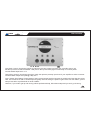
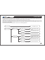
TM
LTO
CONTROL 16
User's Manual
Version 1.5
---English---
Safety Instructions
TM
LTO
All safety and operating instructions should be read before the equipment is installed and operated. We recommend that
installation be carried out by an authorised mobile electronics installation company. Please contact your local ALTO
MobileTM distributor for a list of authorised installers in your country.
To reduce the risk of electric shock and potentially damaging the equipment, do not disassemble the product. No user
serviceable parts inside; refer servicing to qualified personnel.
The equipment should be protected from moisture and rain, especially if mounted in the vehicle's trunk area or any
location that may be susceptible to water ingress.
The equipment should be situated so that its location or position does not interfere with its proper ventilation. For example,
the product should not be situated under carpeting or in a totally sealed enclosure.
Trunk-mounted equipment/amp racks should be well ventilated, using forced air cooling fans if necessary.
The equipment should be situated away from heat sources such as engine exhaust systems and radiators.
This product is designed for vehicles with a 12 VOLT NEGATIVE GROUND electrical circuit. This product must not be
used in vehicles that use a 24 Volt supply or a positive ground electrical circuit.
Great care must be taken when wiring the product to the vehicle's electrical system. Unless you are fully familiar and
trained in wiring automotive electrical systems, installation should only be undertaken by a qualified automotive electrician.
TM
Preface
LTO
Dear Customer,
Thank you for choosing the ALTO MobileTM CONTROL16 2 16 band digital graphic/parametric equalizer. We hope you'll
love the results you get from your new digital sound processor and enjoy using it as much as we enjoyed developing it.
The CONTROL16 is the result of considerable development work in our R&D centres in Europe and the Far East and is
a close cousin of ALTO's professional audio products. We've been designing products for musicians and recording studios
for many years - the product you now have in your hands has a fine pedigree.
The core of our digital audio products is a sophisticated DSP (Digital Signal Processor) coupled with state-of-the-art
algorithms developed by our software team over the last 7 years.
The car audio environment is worlds away from the controlled listening area of the recording studio, and yet much of the
sound processing so important to recording engineers can be applied with spectacular success to the automotive
TM
environment. ALTO Mobile is a specialist division of audio and computer software engineers, but above all we're car
audio enthusiasts. We love the challenge of trying to reproduce studio quality sound inside a moving vehicle.
We're convinced you are an important member of our team and we listen to what you say and take on board your
suggestions. It's this feedback that helps us create the products you want. Thank you.
ALTO MOBILETM TEAM
Block Diagram: CONTROL16
Input L
16 PEQ
High Pass
Delay
Volume
Output L
Input R
16 PEQ
High Pass
Delay
Volume
Output R
Introduction
TM
LTO
In purchasing the CONTROL16, you purchased a very powerful digital sound processor. Some knowledge is required in
order to achieve the best results, but setting the system parameters is easy since it's just a case of stepping through a
series of menus and selecting the desired values.
Once it's all correctly installed, you'll be eager to play with your new buy. If the product has been installed for you there's
nothing stopping you, so go ahead - just read the following warning first and remember to come back and read the rest
of this manual.
Important Warning Substantially boosting the level of frequencies may stress your speakers.
Keep the volume level down until you are familiar with the unit.
If you've purchased the product but haven't had it installed in your vehicle, that's obviously the first thing you'll need to do.
We strongly recommend that you have the unit professionally installed by a specialist company authorised by the ALTO
MobileTM distributor in your country. The installation instructions in this manual are for guidance only and are not intended
to be a thorough explanation of all the steps involved in correctly fitting this unit. The instructions assume that the person
installing the equipment has been trained to carry out such work.
Once you've had a quick play with it you'll have some idea of what the CONTROL16 can do, but it's worth taking time to
understand the menu system and all the parameters that are available for you to adjust. The unit is a very sophisticated
digital graphic/parametric equalizer, but actually it can do even more than that. Once you've worked on setting the sound
the way you like it, you can store it in one of the 48 user preset locations. These can be quickly recalled from the panel
buttons or by using the optional remote control.
TM
LTO
User Interface
Input Gain Controls: Use these controls to match the pre-amp output level from your car audio source unit.
Set the input level so that the SIGNAL LED (next to the input sockets) lights occasionally on musical peaks.
Control16 MAX Input level: 15 V
Output Gain Controls: Use these controls to match the optimum pre-amp input level of your amplifier or active crossover.
Control16 MAX Output level (DSP@ 0 dB): 9.5 V
Input / Output Gain Setting: Proper setting of the input and output levels is important in achieving the best signal-to-noise
ratio. Use of test tones and an oscilloscope will greatly assist in setting the optimum gain levels. For this reason, system
setup is best left to a professional car audio installer.
However, if you need to get up and running without professional help, follow these steps and you won't go far wrong.
User Interface
TM
LTO
Select Preset 01 (FLAT).
Set the ALTO's Output Gains to their 12 o'clock positions.
Turn the Input Gain controls fully counter-clockwise (minimum gain).
Turn the volume control on your CD player to about 75%.
Turn your amplifier input gains to a low setting (say 25%).
Now play some music and increase the ALTO's Input Gains until you see the red CLIP LED next to the input terminals
begin to flash occasionally on musical peaks. This will in most cases be the optimum setting for the input gains. Note that
setting the volume control of your CD player at 75% rather than maximum is done to ensure that the signal output from
the player is pure and undistorted.
Pause the music. Now set the ALTO's Output Gains to about their 3 o'clock position (i.e. 75% of maximum) and set your
amplifier input gains to their Minimum Gain position (i.e. where the amp gives its lowest output level). Note that the
maximum output level from the ALTO processor exceeds 9 volts.
Play some music and gradually increase your amplifier's gain controls until you reach your preferred maximum listening
level, or where you begin to hear any stress from the speakers. If the music sounds distorted with the amp gains at
minimum, reduce the Output Gains on the ALTO unit.
Up/Down Keys: Use these to select the required Parameter Group and the specific parameter that you wish to adjust.
The group or individual parameter is shown in the LCD display. CONTROL16 uses a multi-level menu system. You move
down through the menu - from parameter group to each specific parameter you want to adjust - by pressing ENTER. Only
after pressing the ENTER key are changes made.
Enter Key: While searching using the UP/DOWN keys, the currently selected program does not change.
Choose a Parameter Group using the UP/DOWN keys. Now press the ENTER key. This action moves you one level lower
in the menu system. Use the UP/DOWN keys again to choose a specific parameter to adjust.
Press ENTER again. Now make your changes using the UP/DOWN keys. When you are happy with your changes, press
ENTER once more. The new settings will now be applied and should be audible.
Escape (ESC) Key: Use this key to move back up the menu system without making any changes to the current settings.
TM
Parameter Menus
LTO
Setting the various parameters of the CONTROL16 is achieved with the help of a menu system. While this may be
unfamiliar at first, it should soon become intuitive and easy to find your way around.
After power-up, the display will show the VU-meter data for the left and right input channels and the number of the currently
active preset. Pressing ENTER will put the device into edit mode. Pressing the ESC key at this stage will return you to
the power-up screen display.
The menu functions are multi-layered, as shown in the following diagrams:
Left, Right, L
Select Channel
Setup Equalizer
PEQ 01
PEQ 02
Gain
/
R
15dB step 0.5dB
Frequency
20Hz-20KHz step 1/2oct
Band Width
0.05-3oct step 0.05oct
Gain
/
15dB step 0.5dB
Frequency
20Hz-20KHz step 1/2oct
Band Width
0.05-3oct step 0.05oct
TM
Parameter Menus
LTO
PEQ 16
Setup High Pass
Gain
Output Volume
15dB step 0.5dB
Frequency
20Hz-20KHz step 1/2oct
Band Width
0.05-3oct step 0.05oct
Frequency
20Hz-20KHz step 1/2oct
Slope
Setup Delay
/
Bypass, 1
ord, 2
ord
Adjuist
0, ..., 99 ms step 1 ms
Fine
0, ..., 978 us step 21us
/
12dB step 0.5dB
TM
LTO
Parameter Menus
Load Preset
1, ..., 16, 17, ... 64 Preset
Store Preset
17, ... 64 User Preset
Name editing
Equalizer Flat
All filter 0dB
Bypass System
Bypass
View Eq filter
View all filter
Select Channel
Before editing a parameter, the channel must first be selected using the menu Select Channel function. You can select
the right channel, left channel or both. If you select L R then the changes you make will be applied equally to both
channels.
Parameter Menus
TM
LTO
Setup Equalizer
From here you can select each of the 16 filters. Remember that there are a total of 32 filters (16 per channel) and the
channel setting you choose above dictates whether your changes are applied to just one channel or to both.
Once you have selected a Filter, you can then adjust Gain (cut/boost), Frequency (the centre frequency of the filter), and
Band Width (the extent to which frequencies around the centre frequency will also be adjusted).
Setup High Pass
From here you can set the crossover point (Frequency) and Slope of the built-in High-Pass filter. It's useful for limiting
the amount of bass sent to full-range loudspeakers - this improves power handling and midrange clarity.
The High Pass filter setting is not automatically stored - you need to store it as part of an individual custom preset. Be
careful not to damage your speakers when you switch to a preset that does not use the High Pass filter.
Setup Delay
This allows a tiny amount of delay to be set on each channel. The amount of delay is usually calculated from physical
measurements of the distances between the various speakers and the driver's ears. The delay compensates for the
difference in speaker mounting positions and is generally known as "time alignment".
When applied correctly to all speakers in the system, the result is an improvement in the apparent stage position, height,
depth and the location and focus of the performers on the imaginary stage (usually across the dashboard).
More information is available via our web site.
Output Volume
The Output Volume set here can be stored as one of the custom preset parameters. Heavy equalization can cause
considerable variation in output level when switching from one preset to the next. This allows you to set the same overall
level while maintaining very different tonal contours.
Can also be used as a master gain control. For example, for safety you may want to limit the maximum output level set
by the panel-mounted rotary gain controls.
TM
LTO
Parameter Menus
Load Preset / Store Preset
Allows you to store and recall the factory and custom presets. When storing a custom preset, use the UP/DOWN and
ENTER keys to scroll through the alphanumeric character set and name your new preset.
Equalizer Flat
This command will force all the filters to their 'flat' position. To help avoid accidental resetting of the filters, you are requested
to confirm your choice with the request "Are you sure?" on the display. Press ENTER or ESC.
Bypass System
Allows the signal to pass through the device unprocessed. Warning This will bypass ALL functions set, including the High
Pass filter. To come out of Bypass mode, press the ENTER or ESC keys.
View EQ Filter
This allows you to quickly review the current settings of all the parametric filters (frequency, gain and bandwidth). Use the
UP/DOWN keys to scroll through the filters.
Factory Presets
TM
LTO
The CONTROL16 offers 16 factory preset curves and 48 user definable preset memory locations, giving a total of 64
presets.
Preset 01 Flat
Allows the signal to pass through CONTROL16 with all filters set 'flat'.
Preset 02 Bass Debug
Particularly suited to recordings that display heavy bass equalization around 100Hz, including some contemporary pop
tracks. This region is carefully cleaned and re-balanced by means of a slight boost in the 5KHz range. The extreme
octaves and the central one are left almost untouched.
Preset 03 Bass Presence
Ideal for tracks that lack weight in the bass department. This program gives some additional emphasis in the 100Hz region,
adds a bit of warmth in the midrange and cuts the extreme highs and lows in order to maintain energy levels within an
acceptable range and protect your loudspeakers. Useful with most modern rock digital recordings, which are often a little
shy in bass and midrange energy.
Preset 04 BBC Monitor
If you have a truly capable full-range system, this preset will give you an idea of the sound made famous by the near field
monitors engineered by the BBC decades ago and still used by professionals and enthusiasts worldwide.
Preset 05 Brilliant
This preset gives vitality to recordings that sound lacklustre. The main EQs are centred in the 100Hz, 1KHz and 10KHz
areas. The boost reaches almost 10dB in the high-end, giving more definition to recordings lacking in high band energy.
The low-end is controlled down to 0 dB, while the high-end is still slightly boosted.
Not suited to bright or noisy recordings but can work like magic on classical music, for example.
TM
LTO
Factory Presets
Preset 06 Desub Boost
Do you need to remove power-sapping infra-sonic frequencies, add punch and open out the mid frequencies?
This program aims to do just that. Safe for your loudspeakers and power amps but brilliant and dynamic.
Preset 07 Fem Voice
Two mid frequency and high frequency emphasis curves designed to underline vocal (above all female voices) and leave
the musical background untouched as much as possible. Great on solo vocals but can also do wonders on anything from
opera to modern pop songs.
Preset 08 Hi Definition
This preset was designed specifically to EQ speaker systems that use a bass reflex (vented) system for the low-end, with
its powerful but typically confused and somewhat overblown bass. On a very linear system you'll probably want to switch
it out quick, but when you need to improve the balance between low, mid and highs, it can do a few neat moves.
Preset 09 Infinite
Big and simple. Two enormous peaks centred at 50 Hz and 8 Khz, a central bump up to almost 0dB and attenuations
elsewhere. No, we aren't mad, this is extreme EQ for extreme users. Try it with ultimate disco and techno tracks; it can
be amazing. Warning: lower the volume level before switching to this preset and use with care, listening carefully for
any distortion and speaker over-excursion.
Preset 10 Loudness
The classic 'loudness' filter was once on every home hi-fi power amp, but the trend towards shortening the signal path
saw it all but disappear. But they were useful filters, improving the listening experience at low volumes and in noisy
environments.
CONTROL16 makes use of modern digital DSP techniques to recreate this useful analog filter.
Factory Presets
TM
LTO
Preset 11 Percussion
Four carefully selected regions (100Hz, 250Hz, 6KHz and 15KHz) are given EQ correction to improve the perception of
percussion instruments. This preset is suited to a variety of music, often giving very pleasing and dynamic results while
preventing saturation in the low-end.
Preset 12 Presence
A good choice when you need to underline voices and ambience. It brings vocals a little more forward in the mix without
sacrificing the rest of the spectrum, thanks to a progressive EQ curve with a broad peak around 3500Hz. Great on tracks
rich in natural ambience, such as live concert recordings.
Preset 13 Soft
There are some recordings that on today's CD-quality hi-fi systems give you an audible knife slashing, with a harsh
brightness that's uncomfortable even after a short drive. Take off that edge.
Preset 14 Soft Boost
This preset is derived from the previous one and adds some mid-bass enhancement. It adds 'punch' in order to reinforce
the impact of bass frequencies, while working to smooth off any ultra-sharp edges.
Preset 15 Super Boost
Another form of 'loudness', good for revitalising old rock and pop tracks lacking in dynamics and frequency extension.
Also suited to rebalancing tracks that tend to be too vocal-centred. As a loudness, Super Boost is able to greatly improve
low volume listening, especially where there's road and engine noise.
TM
LTO
Factory Presets
Preset 16 Virtual Sub
Is your system a bit shy at the low-end but otherwise nice and linear? This could be the answer. If you have a system
that's already very capable in the low-end, this EQ setting will be especially powerful on modern dance tracks
Installation Instructions
TM
LTO
Mounting the Unit
CONTROL16 has two fixing 'ears' at each side, allowing it to be firmly screwed to a suitable surface. It may be mounted
vertically or horizontally. Take care not to mount the unit where it may become wet or subject to damage from items placed
in the trunk area.
Signal Inputs/Outputs
The Left and Right Channel input and output terminals are standard phono type sockets. Connect the low-level preamplifier output cables from your car radio/cassette player, CD/receiver or other source unit to the Input terminals of the
CONTROL16.
Connect suitable cables (not supplied) from the Output terminals of the CONTROL16 to the corresponding input terminals
of your power amplifier.
Where to place CONTROL16 in the signal path
If you have an active crossover in your system, you may choose to place the CONTROL16 in the line before or after the
crossover. Usually you would place it in line BEFORE the crossover - all amplifier channels/speakers will then provide a
digitally equalized output signal. However, if you wish to dedicate the CONTROL16's sound processing to only certain
channels/speakers (if using more than one equalizer, for example), you can connect the device in line between the active
crossover and the power amplifier.
Caution: CONTROL16 must always be placed in line BEFORE the power amplifier stage.
Power, Ground and Remote Switch-On (REM) Terminals
Caution: Before making any connections, you must stop power delivery from the battery to avoid accidental short-circuits.
The conventional way is to disconnect the Negative terminal of the battery but beware - this action will disconnect power
from all electrical items in the vehicle, including:
the audio source unit (which may require a code number to reactivate it - do you know the code?)
the security system (which may trigger and sound an alarm from its back-up battery - do you know how to override the
alarm system?)
memory modules (which may suffer memory loss if disconnected for too long).
If you have any doubts you should seek professional assistance first. Professional auto electricians will
TM
LTO
Installation Instructions
isolate individual circuits to maintain power to the remainder of the vehicle's electrical system.
At the far right of the side panel is a POWER INPUT terminal block with three screw terminals. The terminal marked
should be connected to a permanent 12 Volt supply from the vehicle battery.
12V
The terminal marked GND (Ground) should be connected to a cable which is terminated to the vehicle chassis. Ensure
that the point where this cable attaches to the vehicle chassis provides good electrical contact. If drilling a new ground
point, ensure that it is safe (check that there is nothing behind the panel you are about to drill, such as the fuel tank). It
may be necessary to rub away paintwork to expose the metal at this point - in this case, after making a firm screw
connection of the ground cable to the chassis, paint over the terminal point to protect it from the possibility of corrosion.
Where a ground point already exists (for an existing power amplifier, for example) it is generally best practice to ground
the CONTROL16 to this same point on the vehicle chassis.
The terminal marked REM accepts a 12V switched input from the source unit (Cassette or CD player). When the source
unit is switched on, a 12V pulse is sent down this line. The CONTROL16 senses this pulse and switches itself on or off.
The source unit should be equipped with a suitable Remote Switch cable - check the instruction book supplied with your
audio source unit.
If the Remote output from the source unit is already being used to switch on a power amplifier, it is usually possible to
create a 'daisy-chain' by connecting a cable from the REM or Remote terminal on the amplifier to the REM terminal of
the CONTROL16. This avoids the need to run a separate cable from the source unit.
Before reconnecting power to the circuit, double check all connections (be particularly careful to check there are no strands
of wire that could touch the chassis of the CONTROL16 or one of the other terminals).
The power-on LED next to the power input terminal block will light to show the unit is receiving power.
Optional A-LINK Remote Control
TM
LTO
An optional remote control unit is available. This uses a proprietary interface/control system and allows presets to be
selected from the driver or passenger seat even if the unit itself is installed in the trunk.
Connections are made to the A-LINK IN and A-LINK OUT terminals. Follow the instructions supplied with the A-LINK
remote control unit.
TM
LTO
Further Information
Because of the nature of our digital sound processors and the variety of effects that can be achieved with them, there
are operational details, tips and advice too numerous to include in an instruction manual such as this. For additional
information, please visit our website at www.altomobile.com, which includes a technical discussion forum where users
can exchange ideas.
Troubleshooting
Power LED not lit: Is the Remote switch cable from the source unit (Cassette or CD Player) attached to the REM terminal
of the CONTROL16, and is the source unit switched on? Are the 12V and GND (Ground) terminals connected correctly?
Is the Ground cable properly attached to the chassis of the vehicle or to an existing ground point that is known to be OK?
No Sound: Adjust the level of the Input Gain Controls. Adjust the level of the Output Gain Controls. Are the Input and
Output signal cables correctly connected? If there is only sound from one channel, swap the Left and Right channel Input
cables at the CONTROL16 - if the fault moves to the other channel then the fault is with the cable or source unit. If the
fault remains in the same channel, swap the Left and Right channel Output cables at the CONTROL16. If the fault still
remains on the same speaker then the fault is with a cable or a unit after the CONTROL16 (power amplifier, active crossover
or the speaker). Check gain controls on those units and any input switching options. If the fault moves to the other speaker
then the CONTROL16 may be faulty-leave it installed in your system and return to your dealer so that they can check it.
Distorted Sound or Low Volume: Adjust the Input and Output Gain Controls of the CONTROL16, and the Input Level
Controls of the power amplifier (and/or active crossover or additional processor where applicable). Check if the amplifier
has a built-in crossover network - is it switched correctly?
R
TM
Your ALTO Warranty
LTO
To be protected by this warranty, the buyer must be able to produce a numbered, machine printed sales receipt (original
only accepted, not a copy) from his supplying dealer that clearly shows the dealer's name and address, the buyer's name
and address, purchase date, model name/number and serial number of the product. ALTO reserves the right to verify
the authenticity of the receipt directly with the supplying dealer.
ALTO warrants the mechanical and electronic components of this product to be free of defects in material and workmanship
for a period of one (1) year from the original date of purchase. If any defects occur within the specified warranty period
that are not caused by normal wear and tear or inappropriate use, ALTO shall, at its sole discretion, either repair or
replace the product.
To obtain warranty service, the product must be returned in its original shipping carton. A description of the problem
will be appreciated.
Damages/defects caused by the following conditions are not covered by this warranty:
a. Misuse, neglect or failure to operate the unit in compliance with the instructions given in the user or service manuals.
b. Connection or operation of the unit in any way that does not comply with the technical or safety regulations applicable
in the country where the product is used.
c. Damages/defects that are caused by force majeure or by any other condition beyond the control of ALTO .
Any repair carried out by unauthorised personnel will void the warranty.
This warranty is extended exclusively to the original buyer (customer of retail dealer) and is not transferable to anyone
who may subsequently purchase this product. No other person (retail dealer, etc.) shall be entitled to give any warranty
promise on behalf of ALTO .
Failure of ALTO to provide proper warranty service shall not entitle the buyer to claim (consequential) damages. In no
event shall the liability of ALTO exceed the invoiced value of the product.
This warranty does not exclude or limit the buyer's statutory rights provided by national law, in particular, any such rights
against the seller that arise from a legally effective purchase contract.
R
R
R
R
R
R
R
TM
Data
LTO
Channel Layout
2 inputs
2 outputs
Analog Input section
Inputs:
Input Impedance:
Max. input Level:
2 RCA - F
400 kOhms
15 V
Analog Output section
Outputs:
Output Impedance:
Max. output level:
2 RCA - F
600 Ohms
9.5 V
Digital / Analog Interface
Amplitude Response:
Signal to Noise Ratio
THD N
Conversion:
20 Hz - 20KHz 1.5 dB
85 dB
0.03 % @ 1KHz 3 dB
18 bit a-d and d-a converters
Parametric filters
Number of bands:
Gain:
Frequency:
Bandwidth (Q):
stereo, 16 per channel
variable from 15dB to 15dB, 0.5dB step
variable from 20Hz to 20KHz, 1/12 octave step
variable from 0.05 to 3 octave, 0.05 octave step
Butterworth filters
HP Frequency:
Slope:
variable from 20Hz to 20KHz, 1/12 octave step
st
nd
Bypass, 1 Order (6dB/oct), 2 Order (12dB/oct)
TM
Data
LTO
Time alignment
Delay Range:
Step Delay Adj:
Step Delay Fine:
variable from 0 to 100ms
1ms
21 s
Output volume
Range:
variable from
Power Supply
Type:
Voltage supply:
Servo - controlled, Switching
11V - 16V DC (negative ground)
Remote Control:
-Alto Mobile A-Link-
12dB to
12dB, 0.5dB step
SEIKAKU ELECTRON INDUSTRY (H.K.) CO., LTD.
No. 1, Lane 17, Sec. 2, Han Shi W. Road, Taichung, 401 Taiwan
http://www.altomobile.com Tel: 886-4-22313737
email: [email protected] Fax: 886-4-22346757
All rights reserved to ALTO Mobile. Due to continued development in response to
customer feedback, product features and/or internal/external design may be changed
without prior notice. No photocopying, translation or reproduction of any part of this
user manual is allowed without prior written permission.Copyright c 2004 Seikaku Electron.
NF01137-1.0