1
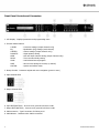
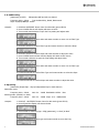
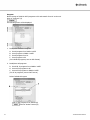
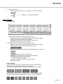
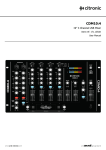
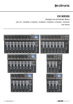
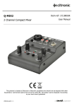
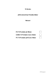
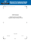
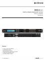
DSM2-6 MKIII DIGITAL SPEAKER MANAGEMENT SYSTEM Order ref: 170.660UK User Manual Features 2 input, 6 output fully balanced 6 band parametric EQs Delay and Limiter functions All inputs/outputs independently controlled Linkable and expandable system PC editing software included Introduction Thank you for choosing the DSM2-6 (MKIII) Digital Speaker Management System. This unit has been designed to offer professional quality performance with open flexibility to address a wide range of sound reinforcement applications. Please read this manual and keep for reference in order to gain the best results from this equipment and avoid damage through misuse. Contents Front panel controls and connectors Page 3 Rear panel controls and connectors Page 4 Panel operation - Input parameter setting Page 4 - Output parameter setting Page 5 - System parameter setting Page 8 PC editing software operation - Connection Page 10 - Input edit screen Page 14 - Output edit screen Page 14 - Input/output EQ screen Page 15 Specification Page 16 Safety Instructions 1. Read these instructions. 2. Keep these instructions. 3. Heed all warnings. 4. Follow all instructions. 5. Do not use this item near water. 6. Clean only with dry cloth. 7. Do not block any of the ventilation openings. 8. Do not install near any heat sources such as radiators, heat registers, stoves or other items (including amplifiers) that produce heat. 9. Do not defeat the safety purpose of the polarised plug. The wide blade is provided for your safety. If the provided plug does not fit into the item or the mains socket, consult an electrician for replacement. 10. Protect the power cord from being walked on or pinched particularly at plug, convenience receptacles, and point where they exit from the item. Only use attachments/accessories specified by the manufacturer. 11. Use only with a cart, stand, tripod, bracket or table specified by the manufacturer, or sold with the item. When a cart is used, use caution when moving the cart/item combination to avoid injury. 12. Unplug this item during lighting storms or when unused for long periods of time. 13. Refer all servicing to qualified service personnel. Servicing is required when the item has been damaged in any way, such as power supply cord or plug is damaged, liquid has been spilled or objects have fallen into the item, the item has been exposed to rain or moisture, does not operate normally, or has been dropped (Note: accidental or cosmetic damage is not covered by the items 12 month warranty) 14. Please keep the unit in a safe environment. 15. Do not store anything on top of the item. To reduce the risk of electric shock, do not remove any cover. No user-serviceable parts inside. Refer servicing to qualified personnel only. The lightning flash with arrowhead symbol within the equilateral triangle is intended to alert the user to the presence of un-insulated “dangerous voltage” within the product’s enclosure that may be of sufficient magnitude to constitute a risk of electric shock. The exclamation mark within the equilateral triangle is intended to alert the user to the presence of important operation and maintenance (servicing) instructions in the literature accompanying this appliance. 2 170.660UK User Manual Front Panel Controls and Connectors 1. LCD Display - Displays parameters and programming menu 2. Function Select Buttons: X-OVER - Crossover settings (output channels only) EQ - Equalisation (EQ) settings (each channel) LIMITER - Limiter settings (output channels only) POLARITY - Signal polarity setting GAIN - Gain and input channel setting (output channels only) DELAY - Time correction delay setting LOAD - Load selected stored program SAVE - Save current settings to memory (or delete) SYSTEM - System and utilities menu 3. Rotary Encoder - Parameter adjust and menu navigation (press to enter) 4. Input channel LEDs 5. Output channel LEDs 6. Input EDIT/MUTE key - Press to mute, press & hold 3sec to edit 7. Output EDIT/MUTE key - Press to mute, press & hold 3sec to edit 8. USB connection - Type B connector for linking to PC 9. USB indicator - Indicates when USB is connected 3 170.660UK User Manual Rear Panel Controls and Connectors 1. IEC connector - Mains inlet with integral fuse 2. Mains voltage selector - Check mains supply and switch to correct voltage 3. Power switch - Switches mains power to the DSM2-6 4. RS-485 connector - Connection for networking to PC or other DSM2-6 5. Output connectors - Balanced XLR output connectors 6. Input connectors - Balanced XLR input connectors Panel Operation: Input Parameter Setting Press & hold the MUTE/EDIT key for IN A or IN B for 3 seconds to enter edit mode. Pressing a function button edits that particular function for the channel being edited. Turning the rotary encoder adjusts the current selected parameter. Pressing the rotary encoder enters the value for that field Further turning of the encoder navigates to other parameters within the function Pressing other function buttons switches to those other functions instantly 1. Input Polarity setting: [Parameter] Polarity [+] positive [-] negative (independent for each channel) example: 1. Hold IN A MUTE/EDIT button 3secs for edit mode (green LED lit) 2. Press POLARITY and the display will show as below 3. Turn encoder to change polarity 2. Input Delay setting: [Parameter] Delay 0 - 1000ms (independent for each channel) 21μs steps 0 - 10ms, 84μs steps 10-20ms, 0.5ms steps over 20ms example: 1. Hold IN A MUTE/EDIT button 3secs for edit mode (green LED lit) 2. Press DELAY and the display will show as below 3. Turn encoder to change the time value 4 170.660UK User Manual 3. Parametric EQ setting: [Parameter] Input EQ1 – EQ6 (6 independent EQs for each channel) Frequency 20Hz - 20kHz example: Gain -20 - +20dB Bandwidth 0.05Oct - 3Oct 1. Hold IN A MUTE/EDIT button 3secs for edit mode (green LED lit) 2. Press EQ and the display will show as below 3. Turn encoder clockwise to open the Freq setting and adjust value 4. Press the encoder to confirm value and rotate encoder to move over to Gain 5. Press the encoder to confirm Gain and rotate encoder to adjust the value 6. Press the encoder to confirm value and rotate encoder to move over to Bandwidth 7. Press the encoder to confirm Bandwidth and rotate encoder to adjust the value A short press of the EQ function button switches through EQ1 to EQ6 to set each EQ Press and hold MUTE/EDIT key of other channels to repeat process for each in turn Output Parameter setting Press & hold the MUTE/EDIT key for OUT 1 to OUT 6 for 3 seconds to enter edit mode. Pressing a function button edits that particular function for the channel being edited. Turning the rotary encoder adjusts the current selected parameter. Pressing the rotary encoder enters the value for that field. Further turning of the encoder navigates to other parameters within the function. Pressing other function buttons switches to those other functions instantly. 1. Output Gain setting: [Parameter] Gain -12dB to +12dB in 0.1dB steps Select either or both inputs to the output channel example: 1. Hold OUT 1 MUTE/EDIT button 3secs for edit mode (green LED lit) 2. Press GAIN and the display will show as below 3. Turn encoder clockwise to adjust the Gain value 4. Press the encoder to confirm value and rotate encoder to move over to input select 5 170.660UK User Manual 5. Press the encoder to select the input to switch on or off and rotate encoder to select 6. Press the encoder to confirm value and rotate encoder to move over to next input 5. Press the encoder to select the input to switch on or off and rotate encoder to select 2. Output Limiter setting: [Parameter] Dynamic limiter (independent for each channel) Threshold -20dB to +20dB example: Attack 0.3 to 100ms Release 2/4/6/8/16/32x 1. Hold OUT 1 MUTE/EDIT button 3secs for edit mode (green LED lit) 2. Press LIMITER and the display will show as below 3. Turn encoder clockwise to adjust the Thresh value 4. Press the encoder to confirm value, switch to Attack and rotate encoder to adjust 4. Press the encoder to confirm value, switch to Release and rotate encoder to adjust *Release value (2/4/6/8/16/32x) relates to multiple of Attack time 3. Outut Polarity setting: [Parameter] Polarity [+] positive [-] negative (independent for each channel) example: 1. Hold OUT 1 MUTE/EDIT button 3secs for edit mode (green LED lit) 2. Press POLARITY and the display will show as below 3. Turn encoder to change polarity 4. Output Delay setting: [Parameter] Delay 0 - 1000ms (independent for each channel) 21μs steps 0 - 10ms, 84μs steps 10-20ms, 0.5ms steps over 20ms example: 1. Hold OUT 1 MUTE/EDIT button 3secs for edit mode (green LED lit) 2. Press DELAY and the display will show as below 3. Turn encoder to change the time value 6 170.660UK User Manual 5. X-OVER setting: [Parameter] X-OVER Independent HPF and LPF per channel Frequency 20Hz - 20kHz Type Linkwitz-Riley, Bessel, Butterworth Slope 12/18/24/48dB per octave example: 1. Hold IN A MUTE/EDIT button 3secs for edit mode (green LED lit) 2. Press X-OVER and the LPF display will show as below 3. Turn encoder anticlockwise to open the Freq setting and adjust value 4. Press the encoder to confirm value and rotate encoder to move over to Filter Type 5. Press the encoder to confirm Filter Type and rotate encoder to select the Slope 6. Press the encoder to confirm Slope and rotate encoder to adjust the value 7. Press X-OVER function button and the display will switch to HPF screen 8. Turn encoder clockwise to open the Freq setting and adjust value 9. Press the encoder to confirm value and rotate encoder to move over to Filter Type 10. Press the encoder to confirm Filter Type and rotate encoder to select the Slope 11. Press the encoder to confirm Slope and rotate encoder to adjust the value 6. EQ setting: [Parameter] Output EQ1 – EQ6 (6 independent EQs for each channel) Parametric mode: Frequency 20Hz - 20kHz Gain -20 - +20dB Bandwidth 0.05Oct - 3Oct Shelving mode: (Hi Shelf, Lo Shelf) Frequency 20Hz - 20kHz example: Gain -20 - +20dB Slope +6 or +12dB/octave 1. Hold OUT 1 MUTE/EDIT button 3secs for edit mode (green LED lit) 2. Press EQ and the display will show as below 3. Turn encoder to select EQ type – PEQ (parametric), Lo Shelf, Hi Shelf 4. Press the encoder to confirm type and rotate encoder to move the Freq 7 170.660UK User Manual 5. Press the encoder to confirm value and rotate encoder to move over to Gain 6. Press the encoder to confirm Gain and rotate encoder to adjust the Slope/Bandwidth value 7. Press the encoder to confirm Slope/Bandwidth A short press of the EQ function button switches through EQ1 to EQ6 to set each EQ Press and hold MUTE/EDIT key of other channels to repeat process for each in turn System Parameter Setting All system settings can be stored in the internal memory of the DSM2-6 mkIII. These functions are edited in a similar way to the input/output channel functions. Pressing the relevant function key opens the current status in the LCD display and these values may be adjusted using the rotary encoder and saved. 1. Load function: [Parameter] Load channel settings from one of the 30 internal programs example: 1. Press LOAD and the display will show as below 2. Turn encoder clockwise to select the required program and press to confirm Channel settings will now all be set as per the selected program 2. Save function: [Parameter] Save current channel settings to one of the 30 internal programs example: 1. Press SAVE and the display will show as below 2. Turn encoder clockwise to select the required program and press to confirm 3. Rotate the encoder to select a letter and press to move onto the next character 4. Repeat the above process until the program name is complete 5. Press and hold the encoder for 3secs to save the program with the selected name Channel settings will now all be saved to the selected program 6. Press the encoder to confirm value and rotate encoder to move over to next input 7. Press the encoder to select the input to switch on or off and rotate encoder to select 8 170.660UK User Manual 3. Delete function: [Parameter] Delete settings in one of the 30 internal programs example: 1. Press SAVE and the display will show as below 2. Turn encoder clockwise to select the required program 3. Hold SAVE for 3secs to erase data in the selected program All data in the selected program will now be erased back to default value 4. System function: [Parameter] System menu settings Press SYSTEM and scroll through functions using the rotary encoder. Press rotary encoder to confirm selected function. Rotate the encoder to adjust setting and press to confirm 1. Device ID setting - allocate a number (1 to 250) to each DSM2-6mkIII connected together in a multi-unit setup. 2. Password setting - If required, enter a 6 figure password to lock the controls from being adjusted by unauthorised users. Note: It is essential to remember this password. Make a note of the password and keep in a secure place Test the lock-out by entering a wrong password 3. Power on setting - Select whether all channels are muted on power up Alternatively, all channels will retain previous mute status 4. Backlight setting - Select whether backlight goes off after 10secs without input Alternatively, backlight can stay on continuously 5. Current program - Displays the current selected program 6. System info - Displays the firmware version 9 170.660UK User Manual PC Software Operation Connection The Citronic DSM2-6 mkIII can be operated from a PC via USB and can be linked in multiples over a long-distance network via RS-485 connection. A maximum of 250 units may be linked together by this method. Install the software and any required drivers from the supplied CDROM (also available to download from www.avsl-citronic.com) 10 170.660UK User Manual Screen Shot Connection Connect the DSM2-6 to the PC using the supplied USB cable or serial RS485 to network adapter. Use further network connections to link multiple units together. Switch on the DSM2-6 mkIII and the PC should recognise it as a connected device. If not, repeat the installation process, ensuring all drivers are installed from the CD. In order for the PC to communicate with the DSM2-6, it is necessary to establish a COM connection. Click on “Connection” (G) The following menu will be displayed If known, select the correct COM port. If COM port is not known, open the PC’s Hardware Device Manager (e.g. “Start-Settings-Control Panel-System-Hardware-Device Manager”) Look in “Ports” to identify which port is being used for the DSM2-6 mkIII Click on the “search_id” button to identify the connected unit’s ID number Click OK and the connection process will begin. 11 170.660UK User Manual Program Allows storage of DSM2-6 mkIII programs to PC and transfer from PC to the unit. Click on “Program” (H) The following menu will be displayed 1. Recall/Store Individual Program A. Recall program from DSM2-6 mkIII B. Store program to DSM2-6 mkIII E. Recall program from PC F. Store program to PC (for individual programs, save as DIA format) 2. Recall/Store All programs D. Recall all 30 programs from DSM2-6 mkIII G. Store all 30 programs to PC C. Store all 30 programs to DSM2-6 mkIII (for all 30 programs, save as DAT format) Delete Individual Program Click on the program to be deleted (A) Click the “Delete” button (B) 12 170.660UK User Manual Copy Channel Click “Copy” button The following menu will be displayed Select whether input or output channels Select source and target channels Click “OK” to copy from source to target Device ID Click “Device” button The following menu will be displayed The current device ID can be changed (1) To switch control to another DSM2-6 mkIII, select the new ID number (2) Key to Software Button Controls 13 170.660UK User Manual Input Edit Screen 1. Input Delay setting Click “ms” button to select units - milliseconds (ms), feet (ft), metres (m) Range 0-1000ms or equivalent in distance 2. Input Polarity setting Click “Polarity” button to select polarity (+/-) Output Edit Screen 1. Output Gain setting Virtual Gain control can be adjusted from -12dB to +12dB in 0.1dB steps 2. Output Delay setting Click “ms” button to select units - milliseconds (ms), feet (ft), metres (m) Range 0-1000ms or equivalent in distance 3. Output Polarity setting Click “Polarity” button to select polarity (+/-) 4. X-OVER setting HPF and LPF curves can be clicked and dragged on the frequency graph Alternatively, frequency can be entered in the “Freq” fields Filter type can be change by clicking the “Type” button Slope can be adjusted by clicking the “Slope” button 5. Limiter setting “Threshold” value is the level at which the limiter takes effect (dBu) “Attack” is the speed at which the limiter acts upon the signal “Release” is the ratio of attack speed at which the limiter stops acting 14 170.660UK User Manual 6. Select input channel Input, A, input B, inputs A+B or no input can be selected as follows Input/Output: EQ Edit Screen 1. Input Channel Parametric EQ setting (“Parameter” EQ) EQ1-EQ6 curves can be clicked and dragged on the frequency graph Frequency can be entered in the “Freq” fields Bandwidth (in octaves) can be entered in the “Oct” fields Gain (dB) can be entered in the “dB” fields 2. Output Channel Parametric EQ setting (“Parameter” EQ) EQ1-EQ6 curves can be clicked and dragged on the frequency graph Filter type can be selected by clicking the Type button EQ can be bypassed by clicking the Bypass button (black=on, red=off) Frequency can be entered in the “Freq” fields Bandwidth (in octaves) can be entered in the “Oct” fields Gain (dB) can be entered in the “dB” fields - or if Shelving EQ type is selected Slope can be adjusted by clicking the “Slope” button [12dB button image] Graphic Display EQ and X-OVER curves may be switched on and off on the graphic display. This can help to visually separate each curve for editing. Click the curve content buttons to toggle each type on (blue) or off (grey) Curves for each channel may be switched on and off on the graphic display. Click the channel buttons to toggle each channel on (colour) or off (grey) 15 170.660UK User Manual EQ Curve Display Clicking and dragging the number on screen can adjust frequency and gain X-OVER Curve Display Clicking and dragging “L” or “H” on screen can adjust cut-off frequency Specification Power supply AC 115V/230V 50Hz/60Hz Fuse T315mA Frequency response 20Hz - 20kHz Power consumption <25W Dimensions 483 x 44 x 220mm Weight 3.19kg Errors and omissions excepted. Copyright© 2012. AVSL Group Ltd. 16 170.660UK User Manual