1
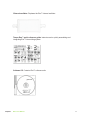
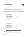
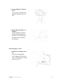
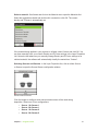
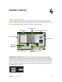
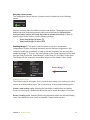
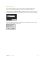
eon
TM
pc-based controller
user guide
for vers. 3.0.11 software
Contents
7
7
9
12
Chapter 1: Eon™ at a Glance
14
14
Chapter 2: Getting Started
20
20
20
21
21
24
Chapter 3: Program Control
26
26
27
28
30
31
31
32
Chapter 4: Heater Control
33
33
33
34
34
35
36
37
38
38
39
39
Chapter 5: Settings
Eon™ Connectors
Accessories
Mirage™ Air-Cooling System
Eon™ System Assembly
Program Control Screen
Process List
Layer List
Layer Properties List
Layer Properties Defined
Heater Control Screen
Heating Cycle List
Heater Settings List
Heater Control Buttons
Heater Thermostat
Temperature & Power Indicators
Advanced Settings
Settings Screen
Backup & Restore
Restore Defaults
Period Control
Relay Control
Sensor Zeroing
Log
Sensor Alerts
Select Sensor Type
Auto Abort on Max Power
Rate Max/Min Auto Abort
Contents
2
Contents
40
40
40
41
Chapter 6: Manual Mode
42
42
42
43
43
43
43
43
43
44
Chapter 7: Vertical Tool Bar
45
45
46
46
46
46
47
47
Chapter 8: Status
48
48
Chapter 9: Green Status Bar
49
49
49
50
50
Chapter 10: Graphs
Contents
Manual Control
Adjusting Source & Heater Power
Exiting Manual Mode
Using the Vertical Tool Bar
Starting a Deposition
Aborting a Process
Resume or Restart an Aborted Process
Logging Eon™ Status
Zeroing the Sensors
Activating Relay 1 and Relay 2
Switching to Manual Mode
Exiting Eon™ Software
Status Screen
Health, Layer, Material, Frequency, Rate, and Thickness
Zero Sensor
Percentage Complete
Source Power
Temperatures
Manually Zeroing Individual Sensors
Status Indicators and Remote Process Control
Graph Screen
Adjusting Min/Max Range of Graphs
Graphs
Color Key
3
Contents
51
51
51
52
52
53
Chapter 11: Screen Lock
54
Chapter 12: Troubleshooting
55
55
55
56
56
56
57
Chapter 13: Specifications
Contents
Password-Protect Eon™ Screens
Screen Lock Button
Locking a Screen
Setting a New Password
Resetting the Password
Device Parameters
Coating
Measurement
Process Display
Communications
Inputs and Outputs
4
Appendices
58
58
Appendix A: Tempe-Eon™ System
59
59
59
59
59
60
60
60
60
60
61
62
62
62
63
63
63
64
64
65
66
Appendix B: Quick Info
68
69
69
69
69
69
Appendix C
71
71
Appendix D
Tempe-Eon™ System Configuration
Screen Selection Tool Bar
Adding a Process
Renaming a Process
Deleting a Process
Edit the Name, Rate, and Thickness of a Process
Adding a Layer to a Process
Copy a Layer
Re-ordering the Layers
Changing Properties of a Layer
Layer Properties List
Removing a Layer
Deleting a Layer
Changing the Material for a Layer
Selecting Sensor
Heater Control
Creating a Heater Cycle
Cleaning the Sensor with a Heater
Clean Settings
Vertical Tool Bar
Settings
About Eon™
LabVIEW Interface
Software Updates
Inspection & Initial Setup
Warranty
Tooling Factor
Appendices
5
Miscellaneous
72
Index
Miscellaneous
6
1
Eon™ at a Glance
This guide describes Eon™ controller with temperature control (3rd generation) and
Eon™ software version 3.0.11.
Eon™ Connectors
Eon™ Front
Heater and RTD Input/Output
Controls Tempe™ sensor head.
BNC Sensor Inputs
Connects to sensor
head via external
oscillator.
Type K Thermocouple
Inputs
Measures temperature
using thermocouples.
0-5 VDC & Relay Output
Connects the 0-5 VDC output for
the deposition source, the 24 VDC
Mirage™, and the relay control.
Eon™ Back
Power Input
Connects to
24 VDC
power input
RS-232
Connects Eon™ to PC.
(Always use the provided
USB-to-RS232 cable).
LED Indicator
Displays status
Chapter 1
Eon™ at a Glance
7
Warning Make sure the correct hardware is used with Eon™ inputs
and outputs. See proper setup procedures in this manual and in the
Tempe-Eon™ quick reference guide.
Warning Only the provided power supply should be used with
Eon™. Not doing so will damage product and void warranty. Make sure power
supply has a 24 VDC.
Chapter 1
Eon™ at a Glance
8
Accessories
The Eon™ ships with a variety of accessories.
Mirage™ air-cooling system. As part of the Eon™ temperature-compensation
system, this cooling accessory channels compressed, cold air into the Tempe™
sensor in order to maintain consistent temperatures inside crystal compartment.
Mirage power adapter. Combines Mirage™ power supply and relay cables.
Mirage air-cooling tube. Delivers cold air into sensor head cooling tubes.
Chapter 1
Eon™ at a Glance
9
Power supply and cable. Input 100-200 VAC, 50/60Hz, 2 A. Output 24V, 3.75 A,
90W Max.
RS-232 extension cable. Male-to-female serial cable.
USB to RS-232 adapter. Connects RS-232 cable and PC.
Chapter 1
Eon™ at a Glance
10
External oscillator. Replaces the Eon™ internal oscillator.
Tempe-Eon™ quick reference guide. Instructs user in quickly assembling and
integrating Eon™ into existing system.
Software CD. Contains Eon™ software suite.
Chapter 1
Eon™ at a Glance
11
Mirage™ Air-Cooling System
The self-heating Tempe™ sensor employs a unique cooling system called the
Mirage™ Air-Cooling System that connects through the DB-9 port. The Mirage™
forces cold air through the Tempe™ crystal compartment to counterbalance heat.
Relay Input from Eon™
Used for controlling the Mirage™.
Exhaust Port
Quietly expels
and disperses
used air.
BNC Sensor Inputs
1/4” push-to-connect
fitting; 2 ft. (.609
mm) insulated tubing
provided.
Compressed Air Input
(requires facility air supply)
1/4” NPT female connection.
CAUTION Only use filtered
(25 micron max) and oil-free
air (100 PSIG max - 6.9 bar).
How it works
In order to achieve and maintain a specific target temperature on the crystal, the
Tempe™ first heats the crystal to the temperature set in the deposition control menu
of the Eon™ GUI. If the Tempe™ exceeds the desired temperature, the Mirage™
is triggered, blasting the crystal compartment with cold air and returning the crystal
surface to the desired temperature. This type of regulated, hot-to-cold ratio control
mechanism is capable of sustaining a tolerance of +/-1° C.
Because it is triggered by a simple relay input, the Mirage™ can be used as a
cooling device in other applications.
Chapter 1
Eon™ at a Glance
12
Mirage™ Features
Refrigerant-Free Air Cooling
Not only maintenance free and environmentally safe, but when using regulated air
the Mirage™ is easily capable of holding the sensor to a tolerance of +/-1°C.
Maintains Temperature up to 500°C
The Mirage™ produces a temperature output capability of 28°C (50°F) BELOW
the supply air temperature, allowing the Tempe™ sensor head to maintain any
temperature within 50-500°C.
Quiet Operation
While the cold air output is connected to the Tempe™ sensor head through a
cooling line, the Mirage™ reduces noise by muffling and dispersing the hot air
output.
Versatility of Application
Working from a simple relay input, the Mirage™ can be used as a cooling device in
alternative applications.
Warning Operating temperature should not be allowed to
exceed 500°C. Equipment damage will likely result.
Chapter 1
Eon™ at a Glance
13
Getting Started
2
Eon™ System Assembly
The following guide will describe in detail how to integrate the Eon™ controller into a
basic QCM configuration. The QCM depicted below is the Colnatec Tempe™ sensor head
featuring temperature control technology. If using an alternative QCM, skip the steps
highlighted in red. (See Appendix A for connection map of a fully assembled Tempe-Eon™
system).
Connecting to QCM
1. BNC Coaxial Cable to QCM
Spin cable in place using
cable shaft until resistance is
felt. (Twisting cable shaft past
point of resistance may
damage cable). Roll fingertip
over connector to tighten.
2. Heater Control Cable to QCM
The 4-pin LEMO™ connector
provides heater control and TC
measurement. To install, push
until it clicks in place. The other
end is a DB-15 that connects
to the DB-15 heater port on the
Eon™ deposition controller.
Warning Misaligned coupling of LEMO connectors can result in
severe damage to Tempe™.
Chapter 2
Getting Started
14
3. Mirage™ cooling line to QCM
The cooling line is connected to
the Mirage™ via an insulated
cooling tube. Slide “push-toconnect” fitting onto the 3/16”
cooling pipe projecting from the
QCM flange. Featuring an
interior detent, cooling tube will
snap securely in place.
Connecting to Eon™
1. BNC Coaxial Cable to Eon™
Slide coaxial connector onto
BNC.
2. Heater Control Cable (DB-15
Connector) to Eon™
Plug DB-15 connector into
the Eon™ 15-pin male heater
port.
Warning DO NOT allow operating temperature to exceed 500°C.
Equipment damage will likely result.
Chapter 2
Getting Started
15
Hardware and electronics
1. Cold Air Output from Mirage™
to Tempe™
Slide the 3/16” tube onto the
“push- to-connect” fitting on rear
of the Mirage™ cooling system.
The Mirage™ provides a
maximum output of 28˚C (50˚F)
below the compressed air
source.
2. Compressed Air Input to
Mirage™
Connect the Mirage™ to a
filtered and oil-free compressed
air source. (Air fittings may vary
by country but require a 1/4 NPT
female connection.
3. Eon™ Supplies Power to
Mirage™ through Power
Module
The 3-pin solenoid module
provides power to Mirage™.
Tighten integrated screw after
mating to Mirage™. The DB-9
connector on other end attaches
to male I/O port on Eon™.
Chapter 2
Getting Started
16
4. Connect Mirage™ Cable to
Eon™
Connect 9-pin female-side of
Mirage™ cable to Eon™ I/O
port.
5. Relay Cable from Eon™ to
Mirage™
Part of the DB-9 connector
cable bundle that plugs into
the Eon™ I/O port and relay
provides a 2-wire interface
for switching.
Connecting Eon™ to PC
1. Install Eon™ Software onto
PC
Insert the accompanying
Eon™ software CD into disc
drive. Follow prompts to install
software onto PC.
Chapter 2
Getting Started
17
2. RS-232 to Eon™
Plug RS-232 connector into
female serial port on rear
panel. Tighten integrated
screws.
3. RS-232 cable to USB
Adapter
Plug the other end of the
RS-232 cable into the USBto-RS-232 adapter. Tighten
integrated screws.
4. Plug USB-to-RS-232
Adapter into PC
Plug USB-end of the USBto-RS-232 adapter into PC.
Chapter 2
Getting Started
18
5. Connect Power to Eon™
Plug Eon™ power adapter
into AC outlet. Then plug DC
connector into the Eon™.
6. Start Eon™ Software
Start Eon™ software and
navigate to the Program
Control screen to begin
creating your processes.
See Chapter 3.
If drivers are already installed, simply update the drivers when
installing software.
Use only the provided USB cable.
Ensure that the software has been fully installed before connecting
Eon™ to your PC.
Reboot PC following Eon™ software installation.
Chapter 2
Getting Started
19
3
Program Control
Program Control Screen
Click the Program button in the Control Menu to access the Program screen. With this
screen you will be able to create a new process, edit or delete an existing process, as well
as add or remove layers and layer properties.
Layers List
Layer Properties List
Process List
Vertical Tool bar
Create new, or
delete existing
process
Screen Selection Tool Bar
Create new, or
delete existing
layers
Permanently
delete layer
Process List
Create a new process, or edit or delete an existing process. The list contains all of
the available processes.
Create a new process. Selecting the New button located below the Process List
allows you to create and name a new process. Choose either Sequential or CoDeposition, enter name, and press OK. The process now appears on the Process
List.
Delete a process. Pressing delete will permanently delete a process. Once deleted,
a process is only recoverable if it was backed up prior.
Chapter 3
Program Control
20
Renaming a process. Double-click a process in the Process Layers List.
Layers List
Open the Layers List. Click a process name. Layers List displays the current layers
associated with a process. Set the rate, thickness, name, and order of the layers.
Add a layer. Click a process name
Select a layer. Single-click.
Edit layer name, rate, and thickness. Double-click a layer. Modify the name, rate,
and/or thickness. Click OK.
Copy Layer. Select an existing layer and press Copy to produce a copy in the list.
Change order of layers. On the Layers List click and hold a layer, drag the layer up or
down the list, and release the layer where desired.
Remove Layer. On the Layers List click and hold a layer, drag the layer up or down the
list, and release the layer where desired.
Chapter 3
Program Control
21
Create new layer. Select New button located below the Layers List. You can also use
an existing layer by typing in the layer name or pressing the dropdown arrow to reveal a
list of currently available layers.
Layer Properties List
Enter or change values for layers. The Layer Property Value window allows you to enter
or change the value of a layer property. (Note: Material, Source, and Sensor operate
differently than the other items listed on the Layer Properties List).
Open Layer Property Value window. Double-click a layer property at any time, even
during a process run.
Enter a value and click OK or Cancel.
Permanently remove layer. Use the Permanently Remove Layer button to delete a
selected layer. A deleted layer is removed from ALL processes (including those not
selected). Once deleted, a layer is only recoverable if it was backed up prior.
Chapter 3
Program Control
22
Select a material. Scroll down and click on the Material row to open the Materials List.
Select the applicable material and double-click a material or click OK. The correct
density and Z-Factor is automatically set.
Materials list.
If the material being applied in your process is unlisted, select Custom and click OK. You
can then manually enter your custom Density and Z-Factor settings in the Layer Properties
List. Note also that whenever you manually change Density and Z-Factor settings to an
unlisted material, the software will automatically classify the material as “Custom”.
Selecting Sources and Sensors. In the Layer Properties List, click on either Source
or Sensor to open the Source/Sensor configuration window.
Source and sensor selector.
Click the image to configure which sensors and sources will be used during
deposition. Select one of four configurations:
• Source 1 è Sensor 1
• Source 2 è Sensor 1
• Source 1 è Sensor 2
• Source 2 è Sensor 2
Chapter 3
Program Control
23
Layer Properties Defined
The following is a list of settings that defines the parameters of the deposition. All
settings must be set correctly for the software to function properly.
•
•
•
•
•
•
•
•
•
•
Chapter 3
Materials
The material being applied during the deposition process. This entry turns
to “Custom” if the Density or Z-Factor is modified by the user, in order to
prevent mismatch.
Density
The density of the selected material being applied.
Z-Factor
Acoustic impedance factor which is used to compensate for dense
materials and is predefined based on the selected material.
Tooling [%]
The geometric relationship between the substrate and the positioning of
the sensor.
Max Power [%]
Represents the maximum power level Eon™ will deliver to the source
[from 0%-100%], even when the heater requires more power to reach the
set-point temperature.
Proportional
The proportional coefficient that controls the material deposition rate
during the PID phase.
Integral
The integral time constant that controls the material deposition rate during
PID phase.
Derivative
The derivative time constant that controls the material deposition rate
during the PID phase.
Dwell Time
The time specified that follows the completion the predeposition process
before activation of the PID. This delay prevents the PID from engaging
the source power prematurely, giving the material a chance to reach
the sensor. (No material is applied to the sensor directly after the
predeposition process finishes, for the brief time it takes for the material to
initially transition from the source to the crystal in the event that a shutter is
present).
Rise to Soak Time
The time specifying how long it takes Eon™ to raise source power from
0% to desired soak power
Program Control
24
Predeposition process vs. time
•
•
•
•
•
•
•
Chapter 3
Soak Time
Once the soak power is reached, this is the time specifying how long
Eon™ sits at soak power before continuing to “Rise to Predeposit”.
Soak Power
The power percentage that the source will achieve during soak process.
Rise to Predeposit
The time specifying how long it takes Eon to change the current source
power to the power percentage set for Predeposit.
Predeposit Time
The time specifying how long Eon™ will maintain the set “Predeposit
Power” before moving into dwell.
Predeposit Power
The power percentage that the source will achieve during the Predeposit
process.
Source
The source Eon™ uses to control the selected layer/material. The Eon™
has two sources, Source 1 and Source 2.
Sensor
Determines which sensor should be used to control the source selected for
the current layer/material.
Program Control
25
4
Heater Control
Heater Control Screen
Click the Heater Control button in the Screen Selection tool bar to access the Heater
Control screen. With this screen the user will be able to create new heating cycle, edit or
delete existing heating cycles, as well as adjust the heater settings.
Heater Settings List
Heating Cycle List
Temperature & Power Indicators
Heater Thermostat
Vertical Tool bar
Create new, or
delete existing
heater cycle
Screen Selection Tool Bar
Activate heating cycle, heater, or
heater shutoff
Adding heater constants. Before the heater can be engaged, the heater constants
specific to each sensor must be entered into the heater constant fields on the Settings
screen. Click the Settings button in the Screen Selection tool bar. Under the Heater tab
on the Settings screen enter the heater constant data into the Heater Constant A and B
fields. The heater constants for the sensor head were included with the paperwork that
accompanied your sensor.
Chapter 4
Heater Control
26
Selecting correct sensor.
The Temperature Sensor selector is located under the Heater tab on the Settings
screen.
Colnatec currently offers two different sensor head designs. The design being used
determines which temperature sensor setting should be selected. Selecting the
incorrect heater sensor will cause the heater to operate incorrectly. In order to
ensure proper heater function, use the following settings:
• Screw Cap Design è Select TC
• Twist Lock Design è Select RTD
Enabling Mirage™. The heater inside the sensor is part of a “temperature
compensation” system. Activating the heater requires that each component in this
system be made fully operational. In order to activate the heater, the user must first
enable the Mirage™. To do so, first click Settings on the Screen Selection tool bar and
then the Relay Control tab. Select Mirage™ under Relay 2 in the Relay Control area.
The Mirage will now respond to commands issued from the Heater Control screen.
Enable Mirage™
Heating Cycle List
The following section will explain how to create a new heating cycle, and how to edit or
remove an existing heating cycle. The list contains all of the available heating cycles.
Create a new heating cycle. Selecting the New button located below the Heating
Cycle List will bring up a window that allows the user to create and name a new cycle.
Delete a heating cycle. Selecting Delete will permanently delete the selected heating
cycle. Once deleted, a cycle is only recoverable if it was backed up prior.
Chapter 4
Heater Control
27
Heater Settings List
With the Heater Settings List, the user will be able to change the operation of the
heater, such as sensor body temperature, clean time, and heater initialization.
Change a value on the Heater Settings List. Double-clicking on a selection brings up
the Heater Settings Value window, which allows the user to edit the value of the setting.
Entering an improper value raises a warning prompt, requiring that the user correct the
error or leave the original value in place.
Chapter 4
Heater Control
28
Heater Settings List management. The items below appear on the Heater Settings
List. By default the values for these items are set to standard levels. Be sure to go
through and adjust each value according to the specific process.
•
•
•
•
Max Power
Represents the maximum power level Eon™ will deliver to the heater [from
0%-100%], regardless of the power levels being demanded by temperature
settings.
Proportional
The proportional coefficient that controls the rate during the PID phase.
Integral
The integral time constant that controls the rate during the PID phase.
Derivative
The derivative time constant that controls the rate during PID phase.
Soak 2
Predeposition process vs. time
•
•
•
•
•
Chapter 4
Rise to Soak Time
The time specifying how long it takes Eon™ to raise heater power from 0%
to desired soak power
Soak Time
Once the soak power is reached, this is the time specified that the Eon™
sits at soak power before continuing to Rise to Soak 2.
Soak Power
The power percentage that the source will achieve during soak process.
Rise to Soak 2 Time
The time before Eon™ changes the current source power to the power
percentage set for Soak 2.
Soak 2 Time
Time Eon™ will maintain the set Soak 2 power before entering PID mode.
Heater Control
29
•
•
•
•
•
Soak 2 Power
Power percentage that the source will achieve during Soak 2 processes.
Stabilization Time
A placeholder for future Eon™ versions that has no effect on heating cycles.
Heater Set-point
Temperature desired for the heater to reach.
Clean Time
Time the heater will remain at the Heater Set-point temperature. Once time is
complete, heater shuts down and program enters cooling stage.
Cool Time
Time Mirage™ will operate reduce sensor temperature to a desired level.
Heater Control Buttons
The Clean button
activates the selected heating cycle, which is used to
remove deposited material from the crystal surface.
During a typical Clean procedure, Soak and Soak 2 phases engage. Once soaking is
complete, the heater is triggered and guided by the parameters it has been assigned on
the Heater Settings List. The program will first raise the sensor body to the Set Point
temperature, maintain the temperature for the Clean Time duration, and then “force-cool”
for the time specified by the Cool Time entry. Selecting Heater Shutoff deactivates a
cleaning cycle.
The Activate Heater button
manually activates the heater. The program
raises the temperature to the Set Point and maintains that temperature indefinitely until
the heater is manually shutoff. Unlike the Clean button. The Activate Heater button
provides no automated control over clean and cool times. Otherwise, just as with the
Clean command, the Activate Heater command engages Soak and Soak 2 and triggers
the heater. Selecting Heater Shutoff deactivates the Activate Heater command.
The Heater Shutoff button
instantly deactivates the heater, regardless of
current process or cycle status. Note: If selection of Heater Shutoff is not followed by use
of a forced-cooling method (e.g., Mirage), the temperature of the sensor head will cool
slowly.
Chapter 4
Heater Control
30
Heater Thermostat
The Heater Thermostat provides real-time display of sensor body temperature.
An arrow marker
indicates the current set point for the sensor body temperature.
Temperature & Power Indicators
Temperature & Power Indicators provide a live reading of the current temperatures of the
sensor body and heater, the preset sensor body temperature, and heater power.
The Set Point Temperature indicator
displays the target temperature chosen
by the user in the Heater Settings list. The heater will engage or disengage as needed to
reach this desired temperature.
The Sensor Temperature indicator
sensor.
displays the current temperature of the
The Heater Power indicator
monitors the power levels the Eon™ is issuing the
heater in order to raise or lower heater temperature to achieve the predetermined
temperature.
Warning The Abort button
DOES NOT shut off the heater.
The Abort button is used to cancel a process in progress or manual
mode only.
Chapter 4
Heater Control
31
Advanced Settings
Skipping soaking steps
When initiating a heat cycle, the user has the option of skipping Soak and Soak 2 and
initiating the heating cycle directly. The following settings will allow the heater to enter
PID mode to achieve the desired temperature (in this instance a temperature of 125°C):
Clean Settings
Max Power [%]
100
Proportional
15
Integral
5
Derivative
0
Rise to Soak Time [s]
.1
Soak Time [s]
0
Soak Power [%]
0
Rise to Soak 2 Time [s]
.1
Soak 2 Time [s]
0
Soak 2 Power [%]
0
Stabilization Time [s]
0
Heater Set Point [C]
125
Clean Time [s]
60
Cool Time [s]
30
Chapter 4
Heater Control
Bypass settings
32
5
Settings
Settings Screen
Click the Settings button in the Screen Selection tool bar to access the Settings screen.
Use tabs to select settings operations. The Settings screen enables user to perform
numerous tasks such as backing up and restoring settings, opening the log folder,
adjusting period, and managing relays and sensor zeroing settings.
Settings Screen Tab Group
Vertical Tool bar
Screen Selection Tool Bar
General Tab
Backup & Restore
The Backup and Restore commands enable the user to save deposition processes,
heating cycles, and general settings in Eon™ software.
Selecting Backup
Chapter 5
Settings
brings up the Backup screen.
33
On the Backup screen, click on the item you wish to save.
Restoring backed up settings. Selecting the Restore button
the Restore screen.
opens
The user can now restore deposition processes, heating cycles, and general settings by
clicking on the appropriate button. Note: The restoration process will overwrite any of the
current settings you restore.
Restore Defaults
The Restore Defaults button
reinstates all of the settings to default
values. This command is often used if the current settings are producing undesired
results.
Period Control
The Period control tuner
is used to adjust data
collection frequency in increments of 0.1 seconds. The period range is 100 milliseconds
to 1 second.
For precision adjustment, moving the slider
produces an indicator showing the
current value. Value can also be entered using the number control
Chapter 5
Settings
.
34
Entering a period value below 100 miliseconds produces the following warning screen:
Keep period values above 100 ms to avoid misreadings and other performance issues.
Changing the measurement magnitude
only affects the
Status screen. Log files will still be recording in kilo-angstroms.
Relay Control Tab
Relay Control
The Relay Control panel features two relays with independent settings.
Applies during deposition only
(automatic control)
Although the two relays are essentially identical, Relay 2 settings contain the
additional Mirage™ option, which should be selected when using Mirage™ aircooling system.
Start Shutoff. When enabled with a check mark
the Start Shutoff command
opens (turns off) the relay each time a process is started. When the relay is used for
a shutter, Start Shutoff ensures that the shutter is always shut before the deposition
process begins.
If Start Shutoff is disabled
deposition process begins.
Chapter 5
Settings
the relay remains in its present state when a
35
Manual. When Manual is selected, the relay remains in its present state. The user can
close (turn on) or open (turn off) the relay at will.
Start. Relay is closed (turned on) as soon as the process starts.
Predeposit. Relay is closed (turned on) at the beginning of the predeposit phase during
the predeposition process.
Auto Deposition. Relay is closed (turned on) just before the PID starts, activating as
soon as Dwell Time (preset) is initiated. Once Dwell Time concludes, Auto Deposition
begins. This process is designed to prevent the Automatic Deposition from engaging
prematurely, providing a window of time between the shutter opening and the material
reaching the substrate. This selection is specifically designed for shutters.
Mirage™ (Relay 2 Only). When the heater is active, Eon™ uses Relay 2 to control
Mirage™. In order to activate the heater, the Relay 2 Mirage option must be selected.
While the heater is active, Relay 2 settings cannot be changed (unless the user is in
Manual mode [for more about Manual mode, see Chapter 6]).
Sensors Tab
Sensor Zeroing
With the Sensor Zeroing panel, the user can select when to zero Sensor 1 or Sensor 2.
Settings for each sensor are identical.
Before Log. Pressing Log button
Start Pressed. Pressing Start button
Chapter 5
Settings
zeros the sensor.
zeros the sensor.
36
Before Layer. Starting a new layer zeros the sensor.
Before PID. Starting PID zeros the sensor.
Warning Failing to zero a sensor before each layer or PID can
produce flawed data. Selecting Before Layer or Before PID will
ensure timely zeroing.
Logs Tab
Log
With the Append Log Name
feature the user can add a specialized name
to the end of the logs recorded by Eon™ software.
Note: If a log recording is already underway, the logging must be restarted for the new
name to take effect.
Note: Naming restrictions built into Microsoft Windows will prevent log recording if the
following characters are used: [ * / > “ : | ]. Eon™ software raises a prompt to warn the
user that the name is invalid. Log files with incorrect characters in the name will not save.
Removing the invalid character makes the warning disappear.
Opening saved log files. Selecting the Open Log Folder
opens
the folder to which the logs are currently being saved. By default this location is
“Public Documents\EON_LOGS\”.
Chapter 5
Settings
37
Alerts Tab
Sensor Alerts
The Sensor Alerts setting
provides the option of enabling or disabling the
crystal failure alerts, which occur when the crystal frequency drifts out of the 5 MHz - 6
MHz range.
Although it is recommended that the sensor alerts generally remain enabled, the user
can disable the notifications in the instance that the crystal is being used in a testing
environment.
Heater Tab
Select Sensor Type
Using the Sensor Selector, users must manually select the type of temperature sensor
that is used inside the sensor head. If using the newer, thermocouple-based sensor,
select TC.
Older sensor heads use RTD sensors. Using an RTD sensor requires the user to enter
the heater constants, which are used to calculate heater temperature. First, select RTD.
The heater constant selection control appears.
Chapter 5
Settings
38
Entering heater constants. The values to be entered are specific to each heater and
are usually shipped with the documentation that accompanied your sensor. To enter
the values, press the Settings button in the Screen Selection tool bar. Enter the
respective values into Heater Constant A and Heater Constant B boxes. Deselect
either box or press the Enter key on your keyboard to see values updated.
If for some reason the values are unavailable, please contact Colnatec Support at
+1 480-634-1449 or [email protected].
Heater Temperature. The Heater Temp readout
provides current
heater readings, which can be useful while setting the heater constants.
Auto Abort Tab
Auto Abort on Max Power
The Auto Abort on Max Power feature provides the user with the option of aborting a
process if the Max Power percentage specificed in the Program settings is reached
and sustained for a period that exceeds the time set in the Abort Delay Time control.
Rate Max/Min Auto Abort
During a process, unexpected occurences (crystal spatter, failed crystal) can cause
sudden spikes or dips in deposition rates. In such instances, undesireable results may
occur. To prevent this from occuring, Eon has the ability to abort the process when rate
fluctuations develop. If the current rate of the deposition goes above the maximum
threshold or below the minimum threshold for longer than the specifed delay times, the
process will automatically abort; so that if your preset rate is 25 Å/s, your Max
Threshhold rate is 6 Å/s, and your Min Threshold rate is 4 Å/s, then the process will
abort at above 31 Å/s or at below 21 Å/s.
Chapter 5
Settings
39
6
Manual Mode
Manual Control
Manual Mode is an alternative operating environment in which the user can exercise
manual control over the sources (Source 1, 2, and heater). To access manual mode,
simply click on the Manual Mode button from any screen.
Adjusting Source/Heater Power
Using the following steps, the source and heater power can be manually adjusted by the
user through the Manual Mode operating environment:
1. Press Manual Mode from any screen
2. Click on the Source Selection Control to select the source that needs to be
manually controlled.
Source Power Indicator
Source Selection Control
Source Power Tuner
3. Clicking on the Source Selection control produces a dropdown list from which
the user can select from available sources.
4. Use the Source Power adjustment buttons to increase or decrease the power
of the selected source in increments of 0.1%, OR click directly onto the Source
Power indicator and enter a specific power percentage. Then, press Enter.
Note: In order for the program to update the source power, the user must enter a new
value and then click in an area other than the Source Power indicator or press
enter.
Chapter 6
Manual Mode
40
Exiting Manual Mode
Click the Abort button
operating environment.
to exit Manual Mode and return to the standard
Note: Pressing the Abort button returns both sources to 0 power.
important When the user manually adjusts the value of the source
power output, the source will no longer be controlled by the PID,
regardless of the current process. If a source is adjusted during a
deposition, the Eon™ will no longer control the source controlling the
PID or the predeposition processes, as the user has taken full control
over the source. This also applies to the heater. Adjusting source
power to the heater disables the feature in Eon™ that automatically
regulates the temperature of the sensor body, and will also halt the
heater from continuing its initialization process if it is currently in one.
Chapter 6
Manual Mode
41
Vertical Tool Bar
7
Using the Vertical Tool Bar
Like the Screen Selection tool bar, the vertical tool bar is always available. Use the
vertical tool bar to start a deposition, abort a process, record a log, zero the sensors,
activate the relays, enter Manual Mode, or exit Eon™ software.
Starting a Deposition
A deposition process can be started from any screen. The process selected in the
Process List on the Program Control screen or through the Remote Process Control
panel is the process that will run.
Press the Start button
to begin the process. When the process is complete, a
Process Complete notification will appear.
Tip: To create a new process, navigate to the Program screen and select New under the
Process List.
Chapter 7
Vertical Tool Bar
42
Aborting a Process
A process can be aborted from any screen. Pressing the Abort button
active process. Abort is also used to exit Manual Mode.
ends an
Resume or Restart an Aborted Process
A process can be resumed or restarted from any screen. Press the Start button
A window with the option to Resume or Restart will appear. Make a selection.
.
Logging Eon™ Status
Eon™ status can be logged to a monitor log from any screen. Pressing the Log button
saves a monitor log to the monitor log save folder (Public/eon_logs/monitoring”).
When a process is initiated, Eon™ software will automatically begin recording the realtime status of the process to the process log folder (Public/eon_logs/processes). If
a process is started while an Eon™ monitor log recording is in process, Eon™ will
automatically stop recording to the monitor log and begin recording to the process log.
Zeroing the Sensors
The sensors can be zeroed from any screen. Pressing the Zero All Thickness button
zeros Sensor 1 and Sensor 2 at once.
Activating Relay 1 and Relay 2
The Relay 1 and Relay 2 buttons
relays.
Chapter 7
Vertical Tool Bar
,
permit manual control of the
43
Exiting Eon™ Software
Eon™ software can be exited from any screen. Simply press the Exit button
and when prompted, press Exit again.
,
Warning The Abort button
DOES NOT shut off the heater.
The Abort button is used to cancel a process in progress or manual
mode only.
Chapter 7
Vertical Tool Bar
44
8
Status
Status Screen
Navigate to the Status screen by selecting the Status button in the Screen Selection tool
bar. The Status screen displays real-time information on the progress of the process.
Data for each sensor is represented - health, layer, frequency, material, rate, thickness,
and percentage complete. Important information such as source power and temperature
is also displayed.
Percentage Complete
Zero Sensor
Temperatures
Vertical Tool bar
●Health
●Layer
●Material
●Frequency
●Rate
●Thickness
Status Bar
Screen Selection Tool bar
Chapter 8
Status
Source & Heater Power
45
Health, Layer, Material, Frequency, Rate, and Thickness
Layer. The name of the layer being applied.
Material. When the sensor is being used during a deposition to apply material, the
indicator will flash red, informing the user that the sensor is being used to control the
selected source for the material being applied. During this process, the material being
applied is also displayed.
Frequency. Sensor frequency.
Rate. Rate of deposition.
Thickness. Thickness of deposition applied to sensor.
Zero Sensor
The Zero Sensor buttons
zero.
Percentage Complete
The Percentage Complete indicators
zero.
zero corresponding sensor thickness to
corresponding sensor thickness to
Source Power
The Source Power indicators display the current power being applied to Source 1 (S1
Power [%]), Source 2 (S2 Power [%]), and heater (Heater Power [%]).
Chapter 8
Status
46
Temperatures
Body Temp. The current temperature of the sensor body, which is connected through
TC1.
TC2. Axillary thermocouple connection.
Manually Zeroing Individual Sensors
Click the Zero Sensor button that corresponds to the sensor to be zeroed.
Chapter 8
Status
47
9
Green Status Bar
Status Indicators and Remote Process Control
A fixed menu available from any screen, the Green Status bar serves a variety of display
and control functions.
Status Indicator
Time Indicator
Status Bar Heater Indicator
Process Control
Status Indicator. Displays process Eon™ is currently performing. Information updates in
real-time as Eon™ performs each task.
Status Bar Heater Indicator. Displays the current status of the heater.
When Eon™ is supplying power to the heater, the indicator turns bright red
.
Time Indicator. Displays the run-time of the current active process. The Time Indicator
also retains the run-time of the last completed or aborted process.
Remote Process Control. When a process is selected, the Status screen will display
the first material to run on each sensor. If no materials are selected to be measured by
one of the sensors, the sensor will display None in the Layer and Material indicator.
Chapter 9
Green Status Bar
48
10
Graphs
Graph Screen
To view the Graphs screen, click on Graphs in the Screen Selection tool bar. The
Graphs screen features line graphs for frequency, temperature, rate, power, and
thickness. Unlike real-time data, data in graph-form can provide the user with a
comprehensive, historical perspective on a developing deposition process.
Frequency
Temperature
Vertical Tool bar
Rate
Thickness
Screen Selection Tool Bar
Power
Color Key
Adjusting Min/Max Range of Graphs
Click anywhere on a graph to produce the range adjustment window.
Chapter 10
Graphs
49
Graphs
The graphs provide a visual representation of data gathered by Eon™. The following
data is presented by the graphs:
•
•
•
•
•
Frequency
Displays frequency over time in [Hz]
Rate
Displays the rate of the material application over time in [Å/s].
Thickness
Displays the thickness of material application over time in [kÅ].
Temperature
Displays the temperature over time in [°C].
Power
Displays the power of the sources and heater over time in percentages in [%].
Color Key
The Color Key
displays the color values representing the various
devices being depicted on each graph.
Chapter 10
Graphs
50
Screen Lock
11
Password-Protect Eon™ Screens
The Eon™ Screen Lock enables the user to lock any screen that appears on the Screen
Selection tool bar. Locking a screen helps ensure that the controls and settings on each
screen remain secure and under password protection.
Screen Lock Button
To access the Screen Lock controls, click on the Screen Lock button
is already in place, the password prompt appears.
. If a password
Entering the correct password will exit to the Screen Lock screen.
Chapter 11
Lock Screen
51
If a password is NOT already in place, the Screen Lock screen appears. Use these
controls to lock and unlock screens and change the Screen Lock password.
Locking a Screen
On the Screen Lock screen, select the screen(s) to be locked. Selecting a screen
highlights it.
Click OK to engage Screen Lock protection. When clicked on, the protected screen(s)
will now generate a password prompt.
Setting a New Password
The user may keep an existing password or enter a new password using the password
controls. In order for a new password to be accepted, the Password and Re-Type
Password fields must contain the same password.
Click OK to save new Screen Lock screen settings or Cancel to return to original
settings.
important Leaving password fields empty DOES NOT disable the
Screen Lock. Attempting to access a locked screen will continue to produce
a passport prompt. Leave field blank and click OK to proceed to the Screen
Lock menu. To disable the Screen Lock, unclick any locked screens.
Chapter 11
Lock Screen
52
Clicking OK saves screen lock and password settings.
Resetting Password
To reset the Screen Lock controls password, click on the Screen Lock button
enter the following code into password prompt: 45647kyswx94272fyshq
and
When the Screen Lock screen appears, enter a new password into the password fields.
Chapter 11
Lock Screen
53
12
Troubleshooting
Symptom
Cause
Solution
Frequency reads -2.0
[Hz]
Sensor not detected
Check sensor connection
“Could not connect to
Eon™ after 3 seconds”
message appears
Wrong COM port
selected
Restart and select the
correct COM port
Layer completes
immediately
Thickness is set to 0 in
the layer
Enter a value other than
0 for the layer
Heater shuts off
prematurely
Clean command
improperly selected
Use Activate Heater
command for your
heating cycle
Heater runs without
stopping
Activate Heater
improperly selected
Use Clean command for
your heating cycle
At program start, a
“Wrong Firmware”
notification appears, even
though the firmware is
current
Noise in the RS232 line
Make sure the RS232
line is connected and
secure. Separate the
RS232 line and any high
current power lines.
Crystal warnings fail to
appear
Sensor Alerts disabled
Go to Settings screen
and enable Sensor Alert
for sensor(s) in use
Chapter 12
Troubleshooting
54
13
Specifications
Device Parameters
Density
0.10 to 99.999 [g/cm3]
Z-Factor
0.10 to 15.00
Coating
Density
0.100 to 99.999 [g/cm3]
Z-Factor
0.00 to 15.000
Rate Set-point
0.00 to 9999.99 [Å/s]
Thickness Set Point
0.00 to 9999.99 [KÅ]
Proportional Gain
0.00 to 9999.00 [s]
Integral Time
0.00 to 99.9 [s]
Derivative Time
0.0 to 99.9 [s]
Rise to Soak
0.10 to 9999.9 [s]
Soak Time
0.00 to 9999.99 [s]
Soak Power
0.00 to 100.00 [%]
Rise to Predeposit
0.00 to 999.99 [s]
Predeposit Time
0.00 to 9999.99 [s]
Predeposit Power
0.00 to 100.0 [%]
Dwell Time
0.0 to 9999.9 [s]
Chapter 13 Specifications
55
Measurement
Frequency Resolution
+/-0.002 [Hz]
Display Rate
10x to 1x per second
Crystal Frequency Range
6 [MHz]
Filter
0-1
Alpha
0-1
Process Display
Film
Selected Material
Layer
Layer Being Deposited
Rate
0.00 to 99.9 [Å/s]
Thickness
0.00 to 999.9[KÅ]
Frequency
-3.00 to 6,500,000 [Hz]
Run Time
Hh/mm/ss
Temperature
0 to 999.9 [°C]
Health
0.00 to 100 [%]
Communications
Factory Set
Chapter 13 Specifications
RS-232 [PC version]
56
Inputs and Outputs
Voltage input
24 [VDC]
RS232 Input
One Half Duplex
Sensor Input
Two BNC Connector
TC Output
2 Type K Connectors
0-5 [VDC] Control Output
Dual Relay Output
Chapter 13 Specifications
One DB9 Connector
57
Appendix
A
Tempe-Eon™ System
Tempe-Eon™ System Configuration
Rendering illustrates basic connections of Tempe-Eon™ system.
Eon™ software
installed on
your PC
Eon™ Controller
TC cable
Mirage™
Air-Cooling
System
Relay Source 2
Remote oscillator
Tempe™ Self-Cleaning Sensor
substrate
source
shutter
Appendix A
Tempe-Eon™ System
58
B
Appendix
Quick Info
Screen Selection Tool Bar
The Screen Selection Tool Bar is the collection of buttons used to access the various
screens in which the user will be working. The buttons consist of Status, Graph, Program, Settings, and Heater Control.
Adding a process
1.
2.
3.
4.
5.
6.
Press the Program button to enter the programming screen.
Press the New button located beneath the Process List.
Enter the desired name for the process.
Select the process type - Sequential or Codeposition.
Click OK.
This process is now selectable through the Process List or the Remote
Process Control panel on the Green Status bar.
Note: In order for the program to update the source power, the user must enter a new
value and then click away from the Source Power indicator.
Renaming a process
1. Press the Program button on the Screen Selection tool bar.
2. Double click the process you wish to rename.
3. In the new window, enter the new name for the process.
• Field must not be left blank
• Name must not already exist
4. Click OK.
Deleting a Process
1. Press the Program button in the horizontal tool bar.
2. On the Process List select the Process to be deleted.
3. Press the delete key directly beneath the Process List.
Appendix B
Quick Commands
59
Edit the name/rate/thickness of a process
1.
2.
3.
4.
5.
Click the Program button to enter the Program screen.
Click the process that has the layer to edit.
Double-click the layer to be edited.
Modify the name, rate, and/or thickness.
Click OK to save changes.
Adding a layer to a process
1.
2.
3.
4.
Press the Program button to access the Program screen.
Select the process from the process list. This will open the Process Layers list.
Press the New button under the Process Layers list.
Enter a new name to create a new layer, or select a layer that has already
been created by clicking the arrow on right of the Name and selecting it from
the list of layers.
5. Enter the desired Rate in [Å/s] and the Thickness in [kÅ]. Click OK.
Note: The name cannot be left blank. Typing the name of a layer that is already created
will use that layer’s settings.
Copy Layer
1. Click the Program button to enter the Program screen.
2. Select an existing layer and press Copy to produce a copy in the list.
Re-Ordering the layers
1. Click and drag the layer to the desired location in the list.
2. Layers are executed in numerical order, from top to bottom.
Changing properties of a layer
1.
2.
3.
4.
5.
6.
Press the Program button on the bottom of the screen.
Select the process in the Process List containing the layer that requires editing.
From the Process Layers list select the layer to be edited.
Double-click on the Property to be edited.
In the new window that opens, enter the new value for the property.
Press OK.
Note: If an incorrect value is entered for the property selected, a notification window will
appear displaying the acceptable values for that property.
Appendix B
Quick Commands
60
Layer property list
•
•
•
•
•
•
•
•
•
•
•
•
•
•
•
•
•
Materials: The material being applied during the deposition process. This entry
turns to “Custom” if the Density or Z-Factor is modified by the user.
Density [g/cm^3]: The density of the selected material being applied.
Z-Factor: Acoustic impedance factor which is used to compensate for dense
materials and is predefined based on the selected material.
Tooling [%]: The geometric relationship between the substrate and the
positioning of the sensor.
Max Power [%]: Represents the maximum power level Eon™ will deliver to
the heater [from 0%-100%], regardless of the power levels being demanded by
temperature settings.
Proportional: The Proportional coefficient that controls the material deposition
rate during the PID phase.
Integral: The integral time constant that controls the material deposition rate
during PID phase.
Derivative: The derivative time constant that controls the material deposition
rate during the PID phase.
Dwell Time: The time specified that follows the completion of the predeposition
process and the activation of the PID. This delay prevents the PID from
engaging the source power prematurely, allowing the material to reach the
sensor. (No material is applied to the sensor directly after the predisposition
process finishes, for the brief time it takes for the material to initially transition
from the source to the crystal in the event that a shutter is present).
Rise to Soak Time: The time specifying how long it takes Eon™ to raise
source power from 0% to desired soak power
Soak Time: Once the soak power is reached, this is the time specifying how
long Eon™ sits at soak power before continuing to “Rise to Predeposit”.
Soak Power: The power percentage that the source will achieve during soak
process.
Rise to Predeposit: The time specifying how long it takes Eon to change the
current source power to the power percentage set for Predeposit.
Predeposit Time: The time specifying how long Eon™ will maintain the set
“Predeposit Power” before moving into dwell.
Predeposit Power: The power percentage that the source will achieve during
the Predeposit process.
Source: The source Eon™ uses to control the selected layer/material. The
Eon™ has two sources, Source 1 and Source 2.
Sensor: Determines which sensor should be used to control the source
selected for the current layer/material.
Appendix B
Quick Commands
61
Removing a Layer
1. Press the Program button in the Screen Selection tool bar.
2. From the process list, select the Process with the layer that needs to be
removed.
3. In the Process Layers, list select the layer that needs to be removed.
4. Press Remove directly beneath the Process Layers list.
Note: Removing the layer only removes the layer from the Process Layers list. The layer
can be re-added to the list by pressing “New” and selecting the layer from the
dropdown menu. See “Adding a process” on the first page of this appendix.
Deleting a Layer
1. Press the Program button on Screen Selection tool bar to enter the Program
screen.
2. Select a process that contains the layer to be deleted.
3. After selecting the Layer from the Process Layers list, press Permanently
Delete Layer to delete the layer.
Warning: This action will permanently delete the layer from ALL processes. The layer will
also be deleted from the list of layers. There is no way to recover a layer once
it is deleted.
Changing the material for a layer
1.
2.
3.
4.
In the Program screen, select the layer with the material to be changed.
Double-click on the Material row.
In the new window select a new material.
Click OK.
Note: When editing Density or Z-Factor, the material value defaults to Custom to prevent
contradictions from occurring between the material and the material values.
Appendix B
Quick Commands
62
Selecting sensor and source of layer
Co-Deposition
1. In the Program screen, select the layer to which a sensor/source will be added.
2. Click on the Sensor/Source selection animation to change the sensor/source
combination.
Sequential Deposition
3. In the Program screen, select the layer to which a sensor/source will be added.
4. In the Layer Properties list, scroll down to the Sensor or Source row and
double-click.
5. In the new window, click the animation until the desired sensor/source setup is
displayed
6. Click OK.
Heater control
Activating the heater
1. Press the Heater Control button to enter the Heater Control screen.
2. Select the Process list and, then, the heater process to be run.
3. Press the Activate Heater button under the Settings list.
Shutting off the heater
1. Press the Heater Control button to enter the Heater Control screen.
2. Press the Heater Shutoff button under the Settings list.
Note: Abort does NOT shut off the heater!
Creating a heater process
1. Press the Heater Control button to enter the Heater Control screen.
2. Press the New button located under the Heater Process list.
3. In the new window that appears, enter the desired name for the new heater
processes.
4. Click OK.
Appendix B
Quick Commands
63
Cleaning the Sensor with the heater
1. Press the Heater Control button to enter the Heater Control screen.
2. Select the Process list and, then, the heater process to be run.
3. Press the Clean button under the settings list.
Clean Settings
•
•
•
•
•
•
•
•
•
•
•
•
•
•
Max Power: This is the maximum power that the Eon™ will send to the heater,
regardless of the temperature. This means if the temperature set requires the
heater power to go above the maximum, the Eon™ will prevent the heater from
going any farther and will stay at the maximum power limit.
Proportional: This is the proportional coefficient to control the material
deposition rate during the PID phase.
Integral: The integral time constant to control the material deposition rate
during the PID phase.
Derivative: Derivative time constant to control the material deposition rate
during the PID phase.
Rise to Soak Time: This is the time span that the Eon™ will raise the source
power from 0% to the desired soak power.
Soak Time: Once the soak power is reached, this is the time the Eon™ will sit
at soak power before continuing to Rise to Predeposit.
Soak Power: This is power percentage that the source will achieve during the
soak process.
Rise to Soak 2 Time: This is the amount of time that the Eon™ will take to
change the current source power to the power percentage set for Predeposit.
Soak 2 Time: This is the time that the Eon™ will maintain the set Predeposit
Power before entering PID mode.
Soak 2 Power: This is the power percentage that the source will achieve
during the Soak 2 Processes.
Stabilization Time: This is not implemented and is a place holder for future
versions. Values here will not affect the heating process.
Heater Set-point: This is the desired temperature for the heater to reach
Clean Time [Clean Only]: This is the time that the heater will remain at the
Heater Set-point temperature before cooling off.
Cool Time [Clean Only]: This is the amount of time the mirage will cool the
heater off after the Clean Time has passed.
Appendix B
Quick Commands
64
Vertical tool bar
Starting a deposition
1. A deposition can be started from any screen.
2. Ensure that the desired process to run is selected in the Remote Process
Control panel on the Green Status bar.
3. To start the process, press the Start button on the vertical tool bar.
4. Wait for the Process Complete notification to appear.
Abort button to end a process or exit Manual Mode
1. From any screen, press the Abort button to end a process or exit Manual Mode.
Note: Abort does NOT shut off the heater!
Resuming an Aborted Process
If a process has been aborted before it has been completed, and a new process
has not been selected, the original process can be resumed.
1. To resume a process, press the Start button from any screen.
2. When prompted to Resume or Restart, press Resume.
Logging the status of the Eon™
1. Press the Log button on the vertical tool bar.
Note: Eon™ status can be logged to a monitor log from any screen. Pressing the Log
button saves a monitor log to the monitor log save folder (MyDocuments/eon_logs/
monitoring”).
When a process is initiated, Eon software will automatically begin recording the
real-time status of the process to the process log folder (MyDocuments/eon_logs/
processes). If a process is started while an Eon™ monitor log recording is in
process, Eon™ will automatically stop recording to the monitor log and begin
recording to the process log.
Zeroing Both Sensors Manually
1. Press the Zero All Thickness button on the Screen Selection tool bar.
Activating Relays Manually
1. The relays can be activated from any screen.
2. On the Screen Selection tool bar, toggle the Relay # button to activate the
relays.
Appendix B
Quick Commands
65
Settings
Note: All settings are automatically updated and saved as soon as they are changed.
Adjusting Eon™ period readings
1. Press the Settings button on the Screen Selection tool bar.
2. Select General tab.
3. Click and drag the marker on the Period control to adjust the period time in
increments of 100ms.
Changing Thickness Units [KÅ, Å]
1. Press the Settings button on Screen Selection tool bar.
2. Select General tab.
3. Select the desired thickness measurement units.
Entering the Heater Constants
1. Press the Settings button on the Screen Selection tool bar.
2. Select General tab.
3. Enter the value of Heater Constant A and Heater Constant B.
4. Update the values by unselecting the box or pressing enter.
Note: The heater constants ensure that the heater functions correctly. Each heater has
its own unique values. These values can be found in the documentation that ships
with the product. If these values are unavailable, please contact Colnatec Support
at [email protected] or call 480-634-1449.
Disable/Enable Sensor Failure Alerts
1. Press the Settings button on the Screen Selection tool bar.
2. Select Alerts tab.
3. Check or uncheck the checkmark box of the corresponding sensor to enable
or disable failure alerts.
• Checked: Shows sensor failure alerts
• Unchecked: Hides sensor failure alerts
Append a Log Name to Log files
1. Press the Settings button on the Screen Selection tool bar.
2. Select Logs tab.
3. Enter text to append a log filename
Note: Using the characters */>”:| will cause the filename to be invalid and can prevent
logs from being recorded.
Appendix B
Quick Commands
66
Restore Default Settings
1. Press the Settings button on the Screen Selection tool bar.
2. Press the Restore Defaults button on the settings screen.
3. A prompt will appear warning the user that selecting OK will return all settings
to a default state.
Force Relays to shutoff when a process is started
1. Press the Settings button on the Screen Selection tool bar.
2. In the Relay Control section, check Start Shutoff for the desired relay you wish
to shutoff on process start.
Set when relays activate during deposition process
1. Press the Settings button on the Screen Selection tool bar.
2. In the Relay Control section, select the round radio button associated with the
step during the deposition process when the relay should activate.
• Manual: The relays will not activate during the deposition process
automatically, but can still be controlled by the Relay # button.
• Start: At the start of each layer/material in the process the relay will activate
and will deactivate at the end of each material.
• Predeposit: The relay will activate during the predeposit phase of the
deposition process for each layer/material. The relay will then shutoff at the
end of the deposition process.
• Auto Deposition: The relay will activate during the dwell phase, just before
the PID activation. This allows the dwell time to occur between shutters
release and PID activation.
• Mirage: Eon™ uses Relay 2 to activate Mirage™ when the Tempe™
heater is engaged. Mirage™ MUST be selected before the heater can be
used, allowing Eon™ to control Relay 2 automatically during the deposition
process.
Setting when Eon™ automatically zeros sensor thickness
1. Press the Settings button on the Screen Selection tool bar.
2. In the Sensor Zeroing menu, checkmark each setting associated with the
sensor that is to have its thickness automatically zeroed.
• Before Log: Eon™ zeros thickness when Log button is pressed.
• Start Pressed: Eon™ zeros thickness when Start” button is pressed to start
a new deposition.
• Before Layer: Eon™ zeros thickness each time a new layer/material
engages during the process.
• Before PID: Eon™ zeros thickness each time a new layer/material
activates the PID.
Appendix B
Quick Commands
67
C
Appendix
Safety, Handling, & Support
Warning All electrical components are to be considered extremely
dangerous if tampered with in any way. Colnatec is not liable for any injury
resulting from product misuse, modification, or disassembly.
Warranty Label If the warranty label has been tampered with, “VOID”
will appear where the warranty label was originally placed. If this is visible
at the time of arrival, it is important that you contact Colnatec immediately
after receiving the product.
Appendix C
Safety, Handling, & Support
68
Examine Your new Eon™ for any signs of physical
damage. Also, ensure that the tamper-evident labels
are intact Before shipping, your Eon™ was calibrated and tested by
Colnatec to meet the highest quality standards. It is important that you
take a few minutes to inspect the product to ensure that your equipment
was not damaged or otherwise tampered with during transit.
About Eon™
With the ability to sense deposition and temperature with high precision,
the Eon™ thin film controller is one of the newest advancements in Thin
Film deposition controllers. The Eon™ provides features that help improve
measurement accuracy for better process control.
LabVIEW® Interface
The Eon™ offers a simple LabVIEW® interface that provides an operating
environment that is intuitive, efficient, and impressive. The Eon™ is easy to
set up right out of the box.
Software Updates
The Eon™ interface software can be upgraded on site to provide software
improvements. There will be notifications when these updates become
available.
Inspection and Initial Setup
Examine Eon™ for any signs of physical damage. Also, make sure that the
tamper-evident labels are intact. In order to ensure safe, correct operation
of your Eon™, please follow the step-by-step instructions presented in the
Eon™ Quick Start guide included with your product.
Warranty
Eon™ is warranted to the original purchaser to be free of any
manufacturing-related defects for one year from the date of purchase.
Colnatec reserves the right to repair or replace the unit after inspection.
Appendix C
Safety, Handling, & Support
69
Contact Colnatec Support
511 W. Guadalupe Road, Suite 23
Gilbert, AZ 85233
(480) 634-1449
[email protected]
www.colnatec.com
Appendix C
Safety, Handling, & Support
70
D
Appendix
Tooling Factor
Cr
ys
t
al
Source
Appendix D
Tooling Factor
71
Index
A
Abort 31, 41, 43, 44, 63, 65
Aborting a Process 43
About Eon™ 69
Accessories 9
Activate Heater 30, 54, 63
Activating Relay 1 and Relay 2 43
Adjusting Y Values 49
Advanced Settings 32
B
Backup 33, 34
Backup & Restore 33
Body temperature 28, 31
C
Clean 30, 32, 54, 64
Clean Settings 32, 64
Coating 55
Color Key 49, 50
Communications 56
Copyright 77
D
Delete Layer 62
Deleting a Layer 62
Deleting a Process 59
Drivers 19
E
Eon™ at a Glance 7, 8, 9, 10, 11, 12, 13
Eon™ Connectors 7
Eon™ System Assembly 14
Exiting 41, 44
Exiting Eon™ Software 44
Exiting Manual Mode 41
F
Frequency 34, 38, 45, 46, 49, 50
Index
72
Index
G
Getting Started 14, 15, 16, 17, 18, 19
Graph 49, 59
Graphs 49, 50
Graph Screen 49
Green Status Bar 48
H
Health 46, 56
Health, Layer, Material, Frequency, Rate, and Thickness 46
Heater 14, 15, 24, 26, 27, 28, 29, 30, 31, 32, 36, 37, 40, 41, 44, 46, 48, 50, 61, 63, 64, 65, 66, 67
Constant 26
Control 14, 15, 26, 27, 28, 29, 30, 31, 32, 59, 63, 64
Control Buttons 30
Control Screen 26
Power 31, 40, 46
Settings 26, 28, 29, 30, 31
Settings List 26, 28, 29, 30
Shutoff 26
Thermostat 26, 31
Heating Cycle 26, 27, 30, 32, 54
Heating Cycle List 26, 27
I
Inputs and Outputs 57
Inspection & Initial Setup 69
L
Layer 20, 21, 22, 25, 37, 45, 46, 54, 60, 61, 62, 63, 67
New 22, 37, 60, 67
Deleting 61
Moving (change order) 21
Layer Properties Defined 24
Layer Properties List 20, 21, 22, 23
Layers list 60, 62
Locking a Screen 52
Log 35, 36, 37, 43, 65, 66, 67
Log files 35, 66
Logging Eon™ Status 43
Index
73
Index
M
Manual Control 40
Manually Zeroing Individual Sensors 47
Manual Mode 40, 41, 42, 43, 65
Material 23, 24, 25, 29, 30, 36, 45, 46, 48, 50, 61, 62, 64, 67
Measurement 56
Mirage™ Air-Cooling System 12
P
Password 51, 52, 53
Password-Protect Eon™ Screens 51
Percentage Complete 45, 46
Period Control 34
Predeposition 36, 41
Process Display 56
Process List 20, 42, 59, 60
Program 20, 21, 22, 23, 24, 25, 42, 59, 60, 62, 63
Program Control 20, 21, 22, 23, 24, 25, 42
Program Control Screen 20
Q
Quick Info 59
R
Rate 21, 24, 29, 45, 49, 50, 60, 61, 64
Relay Control 27, 35, 67
Removing a Layer 62
Restore 33, 34, 67
Restore Defaults 34, 67
Resume or Restart an Aborted Process 43
RS232 54
RTD 7, 14, 37
Index
74
Index
S
Safety 68, 69, 70
Screen Lock 51, 52, 53
Screen Lock Button 51
Screen Selection Tool Bar 20, 26, 33, 49, 59
Sensor Alerts 38
Sensor Zeroing 33, 36, 67
Setting a New Password 52
Settings 26, 27, 28, 29, 30, 31, 32, 33, 34, 35, 36, 37, 38, 39, 59, 63, 64, 66, 67
Settings Screen 33
Shutter 24, 35, 36, 61
Software Updates 69
Source 7, 16, 24, 25, 29, 30, 40, 41, 45, 46, 59, 61, 63, 64
Source Power 40, 45, 46, 59
Starting a Deposition 42
Status 30, 43, 48, 65
Status 35, 43, 45, 46, 47, 48, 59, 65
Status Indicators and Remote Process Control 48
Status Screen 45
Support 38, 66, 68, 69, 70
Manual Mode 40
T
TC (Thermocouple) 47, 57
Tempe-Eon™ System 58
Tempe-Eon™ System Configuration 58
Temperature & Power Indicators 26, 31
Temperatures 45, 47
Thickness 21, 45, 46, 49, 50, 60, 66, 67
Time 22, 24, 25, 28, 29, 30, 35, 36, 43, 45, 48, 49, 50, 61, 64, 65, 66, 67, 68
Tooling Factor 71
U
Units 66
Update 66
Updates 69
USB 7, 10, 18, 19
Using the Vertical Tool Bar 42
Index
75
Index
V
Vertical Tool Bar 42, 43, 44
W
Warranty 68, 69
Z
Zeroing the Sensors 43
Zero Sensor 45, 46, 47
Index
76
© Copyright 2014 Colnatec
All information contained within this
technical manual and accompanying
pages are copyright of Colnatec.
All rights reserved. It is a breach of
copyright if this technical manual is
copied, distributed, or reproduced,
in whole or part, using any means
whatsoever, without the prior written
approval of Colnatec.
Colnatec gives no condition or
warranty, expressed or implied,
about the fitness of this technical
manual or accompanying hardware
product. Colnatec reserves the right
to make changes to this technical
manual or accompanying hardware
or design without notice to any
person or company.
Colnatec shall not be liable for any
indirect, special, consequential or
incidental damages resulting from
the use of this technical manual
or the accompanying hardware or
design whether caused through
Colnatec’s negligence or otherwise.
Copyright Info
October 2014
Ver. 3.0.11
77