1
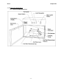
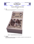
Marvell NanoLab
Member login
Lab Manual Contents
MercuryWeb
Berkeley Microlab
Chapter 8.52
Flexus Thin Film Stress Measurement
(flexus - 380)
1.0
T i t le
Flexus Thin Film Stress Measurement
2.0
Purpose
Flexus (Tencor FLX-2320) is a thin-film stress measurement instrument. It accurately measures the
changes in the radius of curvature of the substrate caused by the deposition of a stressed thin film on
the substrate.
Flexus can also measure the Elastic constant and thermal expansion coefficient of a thin film, if the
thickness of the film and the substrate are known.
3.0
Sc ope
This document describes the procedures of measuring thin-film stress and how to set up a measuring
program. For film elastic constant and thermal expansion coefficient measurements, and advanced 3-D
stress plot, please refer to Section 4.0.
4.0
Ap p lic ab le Do cu me nts
Revision History
Tencor FLX-2320 Thin Film Stress Measurement User Manual (one copy in office, one clean room copy
in the drawer under the Flexus).
5.0
De f in it ions & Proc es s T er mino log y
5.1
Laser Interferometer
Flexus uses a laser interferometer to measure the curvature of a wafer, which is used in the
calculation of the stress in the film deposited on the wafer.
5.2
Intrinsic Stress
The stress of a film at the deposition temperature. It is mainly caused by the atomic structure
mismatch between the film and substrate.
5.3
Thermal Stress
The film stress changes between the deposition and the measurement temperatures. It is mainly
caused by the difference of the thermal expansion coefficients between the film and substrate.
6.0
Safety
6.1
Laser
The Flexus contains two solid-state Class III lasers. Do not defeat the electrical or mechanical
interlocks. When the interlocks are defeated, laser beams of medium power could be present. It is
hazardous. Do not expose the laser beam directly which could damage to your eyes.
flexus
6.2
Chapter 8.52
High Temperature
The hot plate and measurement platform are very hot (up to 500°C) when the heater is operating
for film elastic constant and thermal expansion coefficient measurements. Do not open the
instrument door, touch the inside components, or the wafer, if the temperature displayed on the
upper left corner of the instrument is above 40°C.
7.0
S t a t i st ic a l/ P r oce ss D a t a
The Flexus is tested using two calibrated mirrors (flat and 20-meter curvature) monthly. Please contact
the process staff for the data.
8.0
Av a ilab le Pr oc ess es, G ase s , Pr oc ess N ot es
8.1
8.2
9.0
Available Measurement Programs
8.1.1
Program 100: Standard program for 4” wafers. 50 measure points with 10 mm edge
exclusion. Wafer thickness is set at 525 μm.
8.1.2
Program 150: Standard program for 6” wafers. 50 measure points with 15 mm edge
exclusion. Wafer thickness is set at 690 μm.
Process Notes
8.2.1
Flexus stress measurement only works on blank wafers, not patterned wafers.
8.2.2
Film stress measured is inversely proportional to square of wafer thickness. Please verify
that your wafer thickness matches the program setting, especially if you are using test
grade wafers.
8.2.3
The surface of the wafer must be reflective for the laser to bounce back into the detecting
device. Rough surfaces will scatter the laser and affect the measurement.
8.2.4
The Flexus compares curvature of the wafer before and after film deposition to calculate
film stress. Both pre- and post-deposition measurements are required. If wafer is
coated on both side, e.g. deposited in Tystar LPCVD furnaces, the backside film needs to
be removed before post-deposition measurements is done.
8.2.5
If you forgot to do pre-deposition measurement before film deposition, you still can
measure the film stress. First, strip the backside film on the wafer, and measure it as predeposition. Then, strip the front side film, and measure as post-deposition. The stress will
reverse, e.g. tensile measured is actually compressive, and vice versa. Since there will
be no film left on the wafer, this method only works on a test wafer.
8.2.6
Do not try to adjust any knobs on the Flexus. By doing so, you may cause the laser to
misaligned. The manufacture voids the warranty and service agreement for un-authorized
adjustment on the tool.
8.2.7
For high temperature measurements, the hot plate cover (stored in the drawer under the
Flexus) must be installed and secured with 4 thumbscrews. Make sure the chamber fan
is ON. Failing to do so will overheat the electronic parts and the laser.
E q u ip me nt O pe rat i on
9.1
System Description
The Flexus is controlled by a PC for measurements, data acquisition, and result calculation. The
PC is running WINDOWS 3.1. The measurement results are stored in the user’s subdirectory,
which should be set up when the user is qualified for the tool.
The front view of the FLX-2320 instrument is shown in Section 11.1. For normal stress
measurement, the hot plate cover and thumbscrews are not used. The user needs to select a
-2-
flexus
Chapter 8.52
proper Wafer Locator Ring, which is shown in Section 11.2, for the size of the wafer to be
measured. All the wafer locator rings are stored in the drawer under the Flexus.
9.2
Making a Measurement
9.2.1
Enable Flexus on the WAND.
9.2.2
Check the temperature display on the upper left corner of the instrument. Make sure it is
at room temperature.
9.2.3
Double click the [WIN FLX] icon. The measurement program will start and prompt you to
enter your own subdirectory name.
9.2.4
If the computer has been rebooted, enter login Flexus and password FLX-2320 (casesensitive). At the DOS prompt, enter win to start Windows. Then double click on the
[WIN FLX] icon.
Pre-deposition Measurement
9.2.5
Open the instrument door. Place the wafer, face up, in the wafer locator ring on the
measurement platform. Change the locator ring if it is not the right size for your wafer.
Close the instrument door securely.
9.2.6
Choose [First (no Film)] from the Measure menu. The [First Measurement] dialog box
will pop out. Enter the file name, for data to be stored, and all other fields. Change the
substrate thickness to match your wafer. There is a micrometer on the shelf on top of
the Flexus if you do not know the thickness of your wafer. Make sure the Process
program is the one you want to use. Refer to Section 9.4 to edit the current program or
load other program.
9.2.7
Click the [Measure] button in the [First Measurement] dialog box. The first
measurement starts and you can hear some beeping sounds. When the measurement
finishes, the PC displays two more windows – substrate deflection and light intensity.
If you plan to do more graphic operations, e.g. 3D contour graphs, you need to save the
graphs for future use by choosing [Save As] from the [File] menu. You do not have to do
so if you only want to measure the stress in the film.
9.2.8
Repeat the operation (Sections 9.2.4 to 9.2.6) for other wafers. You can store the data of
different wafers in the same data file with different ID.
9.2.9
When you finished measuring all your wafers, close all the window and exit the program.
Disable Flexus on the WAND.
Post-deposition Measurement
9.2.10 Measure the thickness of the film deposited on your wafer. Make sure the backside film is
stripped completely. Any residue left on the backside will affect your stress measurement
9.2.11 Repeat Sections 9.2.1 to 9.2.4 to start the WINFLX program.
9.2.12 Choose [Single] from the Measure menu. The [Single Stress] dialog box will pop out.
Click the [File] button to select the data file, which contains the pre-deposition
measurement. It is the one you entered in Section 9.2.5. Click the drop down button to
select the wafer ID, which must match the pre-deposition measurement ID for the wafer.
Enter the thickness of the film deposited.
If you have not measured the film thickness, you can enter an approximate one. You can
correct the entry after you have measured it (Section 9.3).
9.2.13 Click the [Measure] button in the [Single Measurement] dialog box. Similar to the first
measurement (Section 9.2.6), the measurement starts and you can hear some beeping
-3-
flexus
Chapter 8.52
sounds. When the measurement finishes, the PC displays two more windows – substrate
deflection and light intensity.
In addition, the measured wafer curvature and stress values are displayed on the graphs.
Negative values indicate a convex surface and compressive stress. Positive values
indicate a concave surface and tensile stress.
If you plan to do more graphic operations, e.g. 3D graphs, you need to save the graphs
for future use by choosing [Save As] from the [File] menu. You do not have to do so if
you only want to measure the stress in the film.
9.2.14 Repeat the operation (Sections 9.2.9 to 9.2.12) for other wafers.
9.2.15 When you finished measuring all your wafers, close all the windows and exit the program.
Disable Flexus on the WAND.
9.3
9.4
Editing, Printing, and Data Transfer of Measurement Results
9.3.1
Perform Sections 9.2.1 to 9.2.4 to start the WINFLX program.
9.3.2
From the Edit menu, choose [Data Files]. Select the data file from the dialog box.
9.3.3
The selected data file will be displayed and you can change all its contents, e.g. film
thickness, and wafer thickness. elastic modulus, and etc. Do not change the Id field,
since it may corrupt the link between the first and single measurements.
9.3.4
The stress will be recalculated automatically after you make the change. If not, choose
[Recalculate] from the Edit menu.
9.3.5
To print the data file, choose [Print] from the File menu. Make sure the printer, which sits
on top of the Flexus, is on and it has paper.
9.3.6
To transfer data files through the network, first click on the [Program Manager] icon, and
then on the [File Manager] icon. Click on the C: drive, locate your personal directory and
select the files you want to transfer. The data files with extension .grp are text files with
the raw data and calculated stress measurement.
9.3.7
Place a floppy disk in the 3.5” drive. Go to the [File] menu and click [Copy]. Enter A: in
the field for the destination drive and hit [OK]. Note: The M: drive is no longer available
as this computer is no longer connected to the network.
Loading, Editing, And Saving Measuring Program
9.4.1
Perform Sections 9.2.1 to 9.2.4 to start the WINFLX program
9.4.2
From the Edit menu, choose [Process Programs]. The Process Program dialog box will
pop-up, with the current program name displayed in the title bar.
9.4.3
To load another program, choose the [Load] button. A list of available programs will be
displayed. Select the desired program then click [OK].
9.4.4
After loading the program, click [Cancel] in the Process Program dialog box to return to
the stress measurement window.
9.4.5
You can customize a process program after you load it. The Process Program dialog box
has the following fields that a user can modify. Use the default if you do not know what to
enter.
Field
Description
Maximum Scan Points
You can specify a maximum of 1250 points. But only 50
points, which is the default, will be saved by the computer for
future reference.
-4-
flexus
Chapter 8.52
9.4.6
Low Intensity Alarm
Use default.
Elastic Modulus
The elastic modulus of the substrate. The drop-down list has
several for common substrates used in the semiconductor
research.
Substrate Thickness
The thickness of the substrate.
Wafer Diameter
The diameter of the wafer in millimeters.
Save Scan
If set to NO, the scan data will not be saved.
Auto Scan
If set ON, the program scans from 10% to 90% of the
substrate diameter. To define your own limits, set it to OFF.
You will be prompted to enter the starting and ending scan
positions after the Wafer Type field is edited.
Hole Diameter
The diameter of the center region to be skipped (for hard or
compact disk applications)
Units
Select MPa or dynes/cm2.
Wafer Type
Select whether your wafer has Flat or Notch.
Laser Selection
There are two lasers in the system, 670nm and 750nm.
Select Automatic allows the system to decide which laser to
use.
After you finish modifying a process program, click [Save]. Make sure you do not
overwrite other programs.
1 0 .0 T ro ub l es ho ot i ng G u id e l in es
10.1
Problem: The computer screen is blank.
Cause: The Flexus is not enabled.
Solution: Enable Flexus on the WAND.
10.2
Problem: Cannot find the WIN FLX icon after enabling Flexus on the WAND.
Cause: Previous user changed the WINDOWS displays.
Solution: Select the [Windows] from the WINDOWS toolbar menu. Click the [Application].
The WIN FLX icon is in the Application window.
10.3
The computer displays a Low Laser Intensity alarm.
Cause: The wafer to be measured is not reflective, i.e. dark film.
Solution: No solution. The wafer cannot be measured.
Cause:
There are certain combinations of film thickness/refractive index that makes the
reflected laser beams to be destructively interfered.
Solution: Select laser of different wavelength in the process program.
-5-
flexus
Chapter 8.52
1 1 .0 F igu re s & Sc he mat ics
11.1 Tencor FLX-2320 (Front View)
-6-
flexus
Chapter 8.52
11.2 Locater Ring used with Three Hot Plate Pins
12.0 Ap pe nd ix
Theory of Operation
The FLX-2320 measures the changes in the radius of curvature of a substrate caused by deposition of
a stress thin film. The stress in the thin film is calculated from the radius of curvature of the substrate
using the following equation:
σ = [ E / ( 1 – ν ) ] [ h2 / 6 R t ]
where:
σ is the film stress (Pa)
E/(1- ν) is the biaxial elastic modulus of the substrate (1.805E11Pa for 100 Si)
h is the substrate thickness (m)
t is the film thickness (m)
R is the substrate radius of the curvature (m)
January 2004 - J. Chang
-7-