1
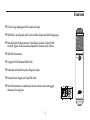
CV4
Large Diaphragm
Multi-pattern Tube
Condenser Microphone
Miktek, LLC
1200 Clinton Street, Suite 15 • Nashville, TN 37203
tel 615.250.2434 • fax 615.346.9298
©2010 All Rights Reserved, Miktek, LLC. Printed May, 2010 v1
www. miktekaudio.com
Table of Contents
Introduction . . . . . . . . . . . . . . . . . . . . . . . . . . . . . . . . . . . . . . . . . . . . . . . . . . . . . . . . . 3 - 4
Features . . . . . . . . . . . . . . . . . . . . . . . . . . . . . . . . . . . . . . . . . . . . . . . . . . . . . . . . . . . . . . 5
Operating the CV4 . . . . . . . . . . . . . . . . . . . . . . . . . . . . . . . . . . . . . . . . . . . . . . . . . . . . 6 - 10
Using the Polar Patterns . . . . . . . . . . . . . . . . . . . . . . . . . . . . . . . . . . . . . . . . . . . . . . . . . . . 6
Connecting your CV4 . . . . . . . . . . . . . . . . . . . . . . . . . . . . . . . . . . . . . . . . . . . . . . . . . . . . 7
Powering the CV4 . . . . . . . . . . . . . . . . . . . . . . . . . . . . . . . . . . . . . . . . . . . . . . . . . . . . . . 7
Setting Up the Signal Level . . . . . . . . . . . . . . . . . . . . . . . . . . . . . . . . . . . . . . . . . . . . . . . . . 8
Microphone Placement . . . . . . . . . . . . . . . . . . . . . . . . . . . . . . . . . . . . . . . . . . . . . . . . . . . 8
The Proximity Effect . . . . . . . . . . . . . . . . . . . . . . . . . . . . . . . . . . . . . . . . . . . . . . . . . . . . . 9
Stand Mounting the CV4 . . . . . . . . . . . . . . . . . . . . . . . . . . . . . . . . . . . . . . . . . . . . . . . . . . 9
Installing the SM7 Shockmount . . . . . . . . . . . . . . . . . . . . . . . . . . . . . . . . . . . . . . . . . . . . . 10
Applications Guide . . . . . . . . . . . . . . . . . . . . . . . . . . . . . . . . . . . . . . . . . . . . . . . . . . . 11 - 19
Vocal . . . . . . . . . . . . . . . . . . . . . . . . . . . . . . . . . . . . . . . . . . . . . . . . . . . . . . . . . . . . . 11
Acoustic Guitar . . . . . . . . . . . . . . . . . . . . . . . . . . . . . . . . . . . . . . . . . . . . . . . . . . . . . . . 12
Piano . . . . . . . . . . . . . . . . . . . . . . . . . . . . . . . . . . . . . . . . . . . . . . . . . . . . . . . . . . . . . 13
Overhead Drum Kit . . . . . . . . . . . . . . . . . . . . . . . . . . . . . . . . . . . . . . . . . . . . . . . . . . . . 14
Stereo Miking Techniques . . . . . . . . . . . . . . . . . . . . . . . . . . . . . . . . . . . . . . . . . . . . . . . . . 15
Coincidental - XY or Crossed pairs . . . . . . . . . . . . . . . . . . . . . . . . . . . . . . . . . . . . . . . . . . . 16
Near Coincidental . . . . . . . . . . . . . . . . . . . . . . . . . . . . . . . . . . . . . . . . . . . . . . . . . . . . . 18
Spaced Pairs . . . . . . . . . . . . . . . . . . . . . . . . . . . . . . . . . . . . . . . . . . . . . . . . . . . . . . . . . 19
Baffled . . . . . . . . . . . . . . . . . . . . . . . . . . . . . . . . . . . . . . . . . . . . . . . . . . . . . . . . . . . . 19
Specifications . . . . . . . . . . . . . . . . . . . . . . . . . . . . . . . . . . . . . . . . . . . . . . . . . . . . . . 20 - 21
You’ve done, done it….. You’ve purchased a truly exceptional piece of audio gear! Congratulations and thank you for
purchasing the CV4 Large Diaphram FET Condenser from Miktek. We know there are a lot of pretty good low cost
microphones available today, but you’re in an elite group of audio engineers where pretty good is just not good enough.
Simply put, that’s why we make our products.
In the following sections of this manual you will find a description of the CV4’s features, step-by-step set-up and
operating instructions along with detailed specifications. In addition, we’ve also included some basic miking techniques
for typical recording and live sound applications. Most of us who’ve purchased the CV4 are already experienced
engineers, so these may seem quite basic. However at Miktek, we want to encourage young or new engineers to use our
microphones, or at least to read our manuals and learn something about recording and live sound. We know you’re serous
about your productions because you purchased such an outstanding audio instrument, and at Miktek, we’re serous about
providing superior products and service to our customers. We appreciate your patronage and hope you enjoying using
your microphones as much as we enjoy making them.
Sincerely,
Michael Ketchell - Managing Director
2
Introduction
The Miktek CV4 is a large-diaphragm tube condenser microphone offering nine pick-up patterns. The CV4’s sound is
truly large and produces a musical response that will please artists, producers and most seasoned engineers alike. The
bottom end is big, warm and tight, with mids that are present and even, along with a high frequency response that’s
sweet and airy. The CV4 is ideal for recording single vocalists, and perfect for acoustic instruments, groups of vocals,
piano, string ensembles, winds, overheads on a drum kit or as ambient room mics. The CV4 utilizes the MK9 capsule
developed by Miktek. This unique capsule features dual 1-inch diaphragms manufactured using 5-micron Mylar with
a 0.4-micron layer of evaporated gold, which is precisely tensioned, mounted to carefully-tuned backplates, and set
back-to-back to create the final capsule. Tight tolerances and special attention to precise machining of the backplate
produce a linear off-axis response that ensures the accuracy of the microphone. The CV4’s electronic circuit design is
unique and features the AMI T7 transformer together with the implementation of high quality, hand-selected exotic
components. Together with an original NOS (new-old-stock) Telefunken EF800 tube, in which the high-voltage circuit
has been uniquely implemented, the microphone challenges the performance of the best-in-class industry standards
without hesitation. The Miktek CV4 is hand-built using components from the US, Europe and Asia, and is tested and
packaged in Nashville, Tennessee, USA. Each microphone includes its serialized frequency response graph created during
final testing. The CV4 is packaged with its swivel mount in a wooden box, which is set inside an aluminum case with the
included power supply unit, 7-pin XLR cable and shock mount.
3
Introduction
With proper care your CV4 will operate trouble free for many years. We recommend you record your serial number in the
space provided below for future reference.
Serial number:_______________________________
Date of purchase:____________________________
Be sure to complete the included warranty registration card or visit mikekaudio.com to register on line. In the unlikely
instance that your microphone would ever require service, please contact us at 615 250 2434 for a Return Authorization
number. If you purchased the microphone outside of the US, please contact your local distributor for service. Please feel
free to call us with any questions you may have about this or any other Miktek product.
4
Features
77 Classic Large-diaphragm Tube Condenser Design
77 MK9 Dual 1-inch Capsule with 5-micron Mylar, Evaporated Gold Diaphragms
77 Nine Selectable Pick-up Patterns; Omni Hyper Cardioid, Cardioid, Half
Cardioid, Figure-8 and a transitional pattern in between each of those.
77 AMI BT4 Transformer
77 Original NOS Telefunken EF800 Tube
77 Individual serialized Frequency Response Graph
77 External Power Supply and 7-pin XLR Cable
77 Wood Presentation Case with swivel-mount, shock-mount and rugged
aluminum Carrying Case
5
Operating the CV4
Using the Polar Patterns
Perhaps the most important aspect of using your CV4, or any other microphone, is to understand its available polar
pick up patterns. Every microphone has a characteristic polar pattern that determines how well it accepts or rejects
signal coming from various areas around the microphone capsule. You can use the CV4’s polar pattern switch, located
on the PS4 power supply’s front panel, to select one of the available polar patterns. The CV4 provides nine polar pick-up
patterns; omniderctional, half cardioid, cardioid, hyper cardioid, figure-eight, plus a transitional frequency in between
each. This give’s you a tremendous amount of versatility and sound possibilities. To understand the basics of patterns
you need to know the three most common patterns; omniderctional, bi-directional or figure-eight. The Omnidirectional
pattern produces a linear response regardless of where the sound source originates (in front of the mic, behind it, to
the side, etc.). If the talent needs to move around and has trouble staying in the same place in front of the mic, using
the omni pattern can be extremely useful since the off axis change will have less of an effect on the frequency response.
When the CV4 is set to the figure-eight pattern the microphone picks up sound directly from the front and back while
rejecting the sound at the sides. When miking an acoustic guitar, a great way to capture same natural ambience is set the
mic in figure 8 and position it between a guitar and a reflective surface.
While Omni and Bi-directional microphones are very useful for a variety of applications, many miking situations in
recording and live sound applications require uni-directional or cardioid microphones. When set to Cardioid, the CV4 will
accept the sound coming from directly in front, and to reject sound coming from behind or from the sides. The cardioid
pick-up pattern allows for better separation of instruments in the studio and more control over feedback in live sound
reinforcement. When positioned correctly, the cardioid pattern allows you to pick up more of the sound you want and
less of the sound you don’t want. In live sound situations, the polar pattern also determines how prone a particular
6
Operating the CV4
microphone is to inducing feedback. Feedback is that nasty howling sound that occurs when a mic is placed too close to a
loudspeaker—the signal from the loudspeaker is fed into the mic, then into the loudspeaker, then into the mic, over and
over again until an oscillating tone is generated. The cardioid pattern utilized by the CV4 is so good at rejecting signal
not coming from directly in front of the microphone, you’ll find that use of the CV4 greatly minimizes feedback problems
when used in live sound applications.
Connecting your CV4
To get started connecting the CV4 locate the included power supply and AC cable. With its POWER switch set to OFF,
plug the AC cable into the back of the power supply, then plug the AC cable into an appropriate power outlet. Be sure
to check the voltage switch is set to the correct voltage for your country. Next, connect the microphone to your power
supply the included 7-pin XLR cable. Be careful to line up the 7-Pin connectors so that you do not accidently bend them.
Now, connect the Mic Output on the CV4 power supply to your mixer’s, mic pre’s or DAW’s (Digital Audio Workstation)
mic input using a standard XLR microphone cable. In order to ensure the proper phase response, please note the PS4’s
output connecter is wired as Pin 1 Ground, Pin 2 hot or positive, and Pin 3 cold or negative.
Important Note: It always a good idea to turn down your mixers main output level control when plugging or unplugging
microphones so you can avoid any unwanted loud pops that could cause damage to your speaker system.
Powering the CV4
Since the CV4 is a tube microphone it needs to be operated by connecting it to the included PS4 power supply unit as
explained in the previous section. Once the power supply is connected to the microphone and mic input, power on the
PS4 power supply. The Power switch illuminates indicating the microphone is on. You’ll need to wait a bit for the tube to
warm up and for the capsule bias circuit to reach the proper voltage. Also, it’s normal for the CV4 to go off momentarily
while switching through the patterns.
7
Operating the CV4
Setting Up the Signal Level
In order to get a good signal, first be sure that the CV4 is connected to a mixer or recorder input that is microphone level.
As explained in the previous section “Powering the CV4”, be sure that the PS4 power supply is connected properly and
turned on. Most quality mixers, mic pre’s and DAW’s provide microphone inputs with a mic trim (“trim” is jargon. the
control is usually called Mic Gain or Level) control. The purpose of the mic trim control is to set a good signal level and
minimize any noise associated with the mic inputs electronics. A good mic pre will also have a Clip or Peak LED to show
you when the input is at overload, the level which distortion begins to occur. To set a good clean level, set the CV4 up
in front of the desired sound source and slowly turn up the mic trim until you see the Clip LED light up. Then, turn the
trim control down until the LED does not light any more. On most microphone inputs, the best setting is when the trim
control is turned up as high as possible without lighting the PEAK LED.
Microphone Placement
To help maximize the quality of your recording, you must pay careful attention to the placement of your CV4, and
specifically, how it is positioned for the instrument or vocalist that you’re miking. Remember, the front side of the
microphone is the same side as the Miktek logo. As you become more experienced in miking techniques, you’ll quickly
realize the microphone placement is critical to getting the sound you want. For more information on typical miking,
see the Application Notes section of this manual. But remember, these examples are at best an approximation of where
you should place the microphone to get the best sound. While placing the mic around any instrument or sound source,
monitor the signal through a set of good quality closed-back headphones and take notice to how just a slight adjustment
can make a huge change in frequency response. As you’re changing the microphone’s position, be sure to check that the
mic input is still set to a good level without clipping, as described in the previous section.
8
Operating the CV4
The Proximity Effect
All cardioid or uni-directional microphones exhibit a phenomenon known as “proximity effect”. The proximity effect is
the increase in low frequency response a microphone exhibits as it is moved closer to the sound source. Vocalist tend
to love this effect since when they get really close to the mic they get the “FM radio”, big bass sound. A good vocalist
with good mic technique will use the proximity effect to adjust their tonal response in real time. The key to developing
the best mic technique is experimentation, along with awareness of the general principle that, when the pattern switch
is set to Cardioid, the closer your CV4 is to a signal source, the greater the bass response. The proximity effect’s bass
lift is caused by the amount of pressure present at the ports that are used to create the directional pattern. Since
omnidirectional microphones do not normally use these ports, they do not have proximity effect.
Stand Mounting the CV4
The CV4 can be mounted to any standard microphone stand using the included mic stand holder or the SM7 shockmount. If you are using a US standard 5/8-inch mic stand, remove the Euro adapter by unscrewing it from the mic holder.
Screw the holder to a solid mic stand, then line up the bottom threaded section of the CV4 to the holder and slowly
rotate the microphone clockwise until it screws on hand tight. Be careful not to cross thread the screws. You can loosen
the bottom thumbscrew on the holder to make left and right adjustments to the mic, and then re-tighten it once it’s in
place. Loosen the side thumbscrew to set the microphone angle and then tighten once it’s in place.
9
Operating the CV4
Installing the SM7 Shockmount
The CV4 kit comes with a SM7 shockmount, which you can use to greatly
reduce any noise transmitted through the mic stand. The shockmounts
are especial useful in reducing the problems caused by a boomy
soundstage, for example when miking overhead cymbals, or even in the
studio with talent that likes to move a lot on a floor that may not be a
solid as it should be.
• To use the CV4 with its included shockmount, screw the shockmount
on a solid mic stand. If you are using a US standard 5/8-inch mic stand,
remove the Euro adapter by unscrewing it from the shockmount.
• Once the shockmount is mounted to the stand, line up the bottom
threaded section of the CV4 to the holder and slowly rotate the bottom
thumbscrew clockwise until it screws on hand tight. Be careful not to
cross thread the screws.
• You can loosen the bottom thumbscrew slightly to make left and
right adjustments to the mic, and then re-tighten it once it’s in place.
Remember, the front side of the microphone is the same side as the
Miktek logo.
• Loosen the thumbscrew to set the microphone angle and then tighten
once it’s in place.
10
Applications Guide
The CV4 is a great microphone choice for many instrument miking situations. Below is a brief guide on using the CV4 in
some typical applications. But as a general rule of thumb, before you use a typical placement, carefully listen to what you
are miking by having the artist play a practice track. Take a walk around the artist as they are playing and listen to what
the instrument sounds like from different positions. Move left and right. Listen over the artist’s shoulders. Place your
head up high and close to the floor. Imagine your ears are the microphones. What do you hear that you like? Then, once
you choose your spot, monitor the signal through a set of good quality closed-back headphones and take notice to how
just a slight adjustment can make a huge change in frequency response. However, before you get into experimenting, the
following basic examples are a good place to start.
Vocals
When using the CV4 on vocals, position the microphone with the logo facing in front of the artist and so that the
microphone grill is approximating 4 to 10 inches away. To avoid unwanted p-popping, use of an external pop filter is
strongly recommended. If no pop filter is available try to set the microphone at a slight angle, which will also help reduce
p-pops. When the CV4’s pattern switch is set to Figure eight, you can record a vocal duet by positioning one vocalist
directly in front of the mic and one directly facing the rear of the microphone. Just remember that the extreme sides of
the microphone pick up almost nothing due to the bidirectional pick up pattern. You can record a group of vocalists by
positioning them in a circle around the CV4 with the pattern switch is set to Omni. The linier response will pickup up all
the vocalists in a 360 degree pattern, evenly. Try to set the balance by having the talent use natural dynamics to blend, or
position each singer at different distances to the mic to create a different balance.
11
Applications Guide
Acoustic Guitar
There are a variety of ways that the CV4 can be used to mic an acoustic guitar. The correct placement will depend on the
type of instrument and what kind of sound you’re looking to capture, for example the tonal quality you want to focus
on, and how much finger slide or pick noise you may or may not want. When miking a standard steel string acoustic, a
good place to start is with the microphone positioned pointing towards the end of the fingerboard at a distance of about
6 inches to 2 feet away from the instrument. You can experiment by moving the microphone slightly in the direction
of the sound hole, which will produce more low frequencies, or move it in the direction of the 12th fret to capture more
high-end or to remove any unwanted boominess. For nylon string acoustic, try positioning the microphone above the
bridge to emphasize more of the attack from the sound of the finger picking, or for less, move the mic closer to the
sound hole. If you have a pair of CV4’s, try one positioned at the fingerboard and the second over the sound hole. Try
positioning one mic in the front of the guitar pointed towards the fingerboard and another over the right shoulder (right
handed player).
Important Note: When using multiple microphones you need to be aware of their phase response. In general, all the
microphones need to be facing in the same direction or you will experience comb filtering and/or phase cancelation. For instance,
in the previous example set up it will be necessary to invert the phase on the over the shoulder microphone since it will be more
than likely end up facing the opposite direction as the front microphone. Any good mic pre will have a Phase reversal switch so be
sure to reverse the phase of any mics facing the opposite direction.
12
Applications Guide
Piano
You can achieve outstanding results using the CV4 on acoustic piano. Several placement approaches can be used
depending on the size of the piano, and the type of sound you are looking to record. When miking a Grand Piano, (for
an ambient sound like that used in a classical recital), a single CV4 can be positioned directly in front of the instrument.
Open the lid to the full position and place the microphone five to twelve feet in front of the instrument. For a more
contemporary sound with better isolation, place two CV4’s inside the piano positioning one over the low strings and
the other over the high strings. To achieve a more realistic sound, it’s a good idea to leave some space between the
instrument and the microphone, especially if you are recording a solo instrument. Also, keep in mind how the track
ultimately needs to fit into the mix. For example, if you are recording a solo performance of Chopin, you would likely
want a very even response and you’d want to capture the left hand sostenuto. However, if you are recording rock and
roll or pop music, you may want the piano to sit within the track in a specific frequency range where less bass is desired.
Nashville engineers, and other good ones from all over the planet, are famous for building the mix as they track, starting
with the microphone placement. You can also try the XY or ORTF stereo mic set-ups described in the following section,
“Stereo Miking Techniques”.
13
Applications Guide
Strings
Place the CV4 one to three feet from the instrument when recording a solo string instrument like a violin. When
recording a string section, try to position one or more CV4’s several feet from the players. If the size of the room permits,
raise the microphones three or four feet above the section and position them at a 45-degree angle, facing down. If
you have two CV4’s, you can try the XY or ORTF stereo mic set-ups described in the following section, “Stereo Miking
Techniques”.
Overhead Drum Kit
Because of its linear, full range frequency response, the CV4 performs outstandingly when used as an overhead cymbal
microphone. The CV4’s big sound and linear response capture the entire kit making them awesome on overheads. You
can position one CV4 on a boom mic stand directly above the kit pointing from front to back. For stereo miking, use two
CV4’s placed over the drum set at a distance of two to three feet depending on the size of the kit. You can experiment
with the exact placement depending on the size of the room and whether you’re looking for an ambient or close-miked
sound. You can also try the XY or ORTF stereo mic set-ups described in the following section, “Stereo Miking Techniques”.
In general, when miking a drum kit, it’s a good idea to start with the overhead mics. Even though you use the overhead
mics mostly for the cymbals, try to get the entire kit to sound great in the overheads. Then it will be easier to just bring
up your individual mics for more attack and thickness in the overall sound.
14
Stereo Miking Techniques
Stereo Miking Techniques
Recording instruments like acoustic guitar, piano and drums, or ensembles (especially in classical or jazz), in stereo
will provide a much more realistic experience for the listener. You can create a stereo recording by simply using your
mixer’s or DAW’s pan controls to place different instruments in between the left and right speakers. However, since
the recorded tracks were likely created with close miking, the stereo mix is void of a lot of information that the listener
would normally enjoy in a live performance. When you record live tracks in stereo, not only will you capture the left
and right position, but you can capture the perspective of depth and distance of each instrument. You’ll also capture an
image that translates the distance between the ensemble and the listener, and, you capture the sound of the acoustic
space surrounding the instrument or ensemble. When recording ensembles in stereo you have better chance of faithfully
reproducing the balance between the instruments that was originally intended by the composer. For most stereo
miking applications, you need to have two microphones with closely matching frequency responses and polar patterns.
Depending on which miking technique you use, the stereo image is created when the combination of microphones pickup
differences in level, time and frequency response.
There are several time-tested techniques for recording in stereo including coincidental or XY pairs, near coincidental or
AB, spaced pairs, and baffled. Following is a brief explanation of these common types stereo miking set ups.
15
Applications Guide
Coincidental - XY or Crossed pairs
Coincidental microphone set ups are where the two microphones’
capsules are set close together on the same axis. The most common
of these is XY or crossed pairs. In the XY set up, the two microphone
capsules are positioned on the same axis, one directly above the other
with the capsules positioned on an angle from 90 to 120 degrees. The
wider the angle, the wider the stereo spread. Since the microphones are
set on the same axis, the distance is constant and there’s little or no delay
difference. Therefore, the stereo image is created by the level difference
of the left and right microphones. Since there is no appreciable delay,
there is less of a chance for phase cancelation and comb filtering so you
can good results when the stereo signal is combined to a mono signal.
MS – Mid side
The Mid side technique makes use of two microphones, with one figure-8
and a second mic either cardidod or omni , or two figure-8 pick patterns.
The first microphone (the mid), either figure-8, omni or cardioid
microphone, is positioned facing directly at the sound source. The second
microphone (the side), with a figure-8 pattern, is positioned on the same
axis directly
16
90
Applications Guide
above or below the first, but with the capsules positioned at a 90-degree angle from
the front. The outputs of the two microphones are often connected to a special MS
matrix mixer, which combines the mid signal with the signal of the side microphone,
both in phase and out of phase. The matrix mixer’s ratio control now used to set the
balance between the mid mic and the combined signal of the side mics to adjust the
width of the stereo spread. You can also connect the two microphones outputs to two
inputs of a stereo mixer, let’s say channel one and two. Next, split the side signal into a
third channel set to reverse phase. Pan channels two and three hard left and hard right
respectively. Channels two and three should be at equal level and always adjusted the
same amount as if they were grouped together. Now use the balance between channel
one and the grouped channels two and three to adjust the width stereo spread.
If you want to create the Mid-side stereo effect after you’ve recorded into your DAW,
record the mid mic on track one, and the side mic on track two. Then, copy track two
to track three, be sure they are aligned perfectly and then reverse the phase on track
three. Now group tracks two and three together so they move with one fader. Then
pan channel two hard left and channel three hard right. At this point you can adjust
the width of the stereo image by change the balance between track one and the group
channels two and three.
17
Figure-8
Cardioid
Applications Guide
Near Coincidental
Near coincidental or AB mic set up used two matched microphones
set relatively close together, facing in opposite directions. The
spacing between the microphones creates a time delay adding
to the stereo effect. The greater the angle the greater the stereo
spread. Less of an angle yields a more narrow spread. There are
a few standards that specify different angles and spacing, with
the most popular being the ORTF (the acronym given to the
French Broadcasting Organization which stands for Office de
Radiodiffusion
Television Française). The ORTF standard specifies
the capsules to be spaced 17cm apart and set at a 110-degree
opposing angle. In this setup the stereo image is created by the
differences between level and time. The stereo image is sharp
however it tends not to be mono compatible.
Spaced Pairs
The spaced pair approach uses two identical microphones set rather
far apart, for example 2 to 20 feet, or more apart, both facing directly at the sound source. The further apart that the
micro phones are placed, the wider the stereo spread.
18
Applications Guide
The instruments in the center of the two microphones will be
heard midway between the left and right speaker. With greater
distance, the off center images are less focused or more diffused.
This set-up tends to capture more ambience from the acoustical
space, which can be very pleasant to the listener, however the
signal tends not to be mono compatible. In some instances were
the microphones are very far apart, a third microphone can be
used in the center to reinforce the clarity of the center image.
Baffled
In a baffled stereo set up, two omni directional microphones are
placed roughly the distance between your left and right ears with
a physical hard or foam baffle placed in-between the two mics. It
uses time differences at low frequencies and level differences at
high frequencies to create the stereo image. The baffle creates a
difference in frequency response between the two microphones,
with less high frequency content heard from the further microphone. Therefore with the baffled set-up, the stereo signal
is achieved by the combination of the differences in level, time and frequency. With the baffled set-up the stereo image
has a tendency to be exaggerated and not mono compatible.
19
Specifications
77 CV4 Typical Frequency Response
20
77 CV4 Polar Response
Specifications
77 Type . . . . . . . . . . . . . . . . . . . . . . . . . . . . . . . . . . . . . Large Diaphragm Nine-Pattern Tube Condenser
77 Polar Patterns . . . . . . . . . . . . . . . . . . . . . . . . . . . . . . . N
ine Selectable; Omni Hyper Cardioid, Cardioid,
Half Cardioid, Figure-8 and a transitional pattern in between each of thos
77 Frequency Response . . . . . . . . . . . . . . . . . . . . . . . . . . . . 20~20000Hz
77 Sensitivity . . . . . . . . . . . . . . . . . . . . . . . . . . . . . . . . . -35 dBV/Pa
77 Equivalent Noise Level . . . . . . . . . . . . . . . . . . . . . . . . . . 16 dB
77 Dynamic range . . . . . . . . . . . . . . . . . . . . . . . . . . . . . . . 117dB
77 S/N Ratio . . . . . . . . . . . . . . . . . . . . . . . . . . . . . . . . . . 78dB 77 Max. SPL . . . . . . . . . . . . . . . . . . . . . . . . . . . . . . . . . . 133 dB
77 Power Supply . . . . . . . . . . . . . . . . . . . . . . . . . . . . . . . . Miktek PS4
Specifications are subject to change without notice.
21
www. miktekaudio.com
1200 Clinton Street, Suite 15 • Nashville, TN 37203
tel 615.250.2434 • fax 615.346.9298
©2009 All Rights Reserved, Miktek. Printed May, 2010 v1