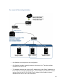
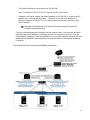
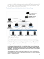
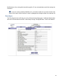
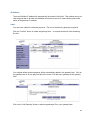
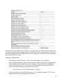
1
WebMux™
Network Traffic Manager
User Manual
(Models A400X, A400XD, A500X, A500XD, and A600X)
Version v11.0.00
(Revision February 2015)
www.avanu.com
Table of Contents
SECTION I - GENERAL INFORMATION ................................................................................................................. 9 About AVANU®.................................................................................................................................................................. 9 WebMux User Manual.................................................................................................................................................... 9 Audience .............................................................................................................................................................................................9 Notice of Rights ...............................................................................................................................................................................9 Notice of Liability.............................................................................................................................................................................9 Trademarks........................................................................................................................................................................................9 Update Information ..................................................................................................................................................................... 10 Packing List....................................................................................................................................................................... 10 Contact Information ...................................................................................................................................................... 10 Mailing Address ............................................................................................................................................................................ 10 Service Center............................................................................................................................................................................... 10 Email................................................................................................................................................................................................... 10 Telephone Numbers................................................................................................................................................................... 10 Hours of Operation...................................................................................................................................................................... 10 SECTION II - WEBMUX MAIN COMPONENTS ................................................................................................ 11 Front View.......................................................................................................................................................................... 11 Rear View........................................................................................................................................................................... 12 SECTION III - WEBMUX TOPOLOGY OVERVIEW ........................................................................................ 14 WebMux Topology Modes ........................................................................................................................................ 14 Two-Armed NAT Mode............................................................................................................................................................. 14 Two-Armed Transparent Mode ............................................................................................................................................ 18 One-Armed Single Network Mode...................................................................................................................................... 20 One-Armed Out-of-Path Mode (OOP) .............................................................................................................................. 21 Details About Out-of-Path Mode............................................................................................................................ 24 IPv6 Considerations ..................................................................................................................................................... 24 High Availability and Configuration....................................................................................................................... 25 1) NAT mode: ....................................................................................................................................................................... 26 2) Transparent mode: ....................................................................................................................................................... 26 3) Single Network mode.................................................................................................................................................. 27 4) Out-of-Path mode ......................................................................................................................................................... 27 How to Add a Loopback Adapter........................................................................................................................... 27 Installing the Microsoft® Loopback Adapter.................................................................................................................. 28 2 Configuring the Microsoft® Loopback Adapter ............................................................................................................ 28 Linux® 2.4/2.6 Systems:.......................................................................................................................................................... 29 SUSE® Enterprise Linux® 9: ................................................................................................................................................ 29 Hewlett Packard® HP/UX® 11.00 and 11i:.................................................................................................................... 30 FreeBSD®:...................................................................................................................................................................................... 30 Oracle® Solaris®:........................................................................................................................................................................ 30 Apple® Servers: ........................................................................................................................................................................... 30 SECTION IV - CONFIGURING THE WEBMUX................................................................................................. 31 Getting Started ................................................................................................................................................................ 31 Network Terminology................................................................................................................................................................. 31 Hardware Setup - Collect Information............................................................................................................................... 32 Hardware Setup - Network Environment......................................................................................................................... 32 Hardware Setup - Configuration Summary .................................................................................................................... 32 SECTION V - Management Console........................................................................................................................ 43 Login ..................................................................................................................................................................................... 44 Start Login Page: ......................................................................................................................................................................... 44 User ID:............................................................................................................................................................................................. 44 Password: ........................................................................................................................................................................................ 44 Login:.................................................................................................................................................................................................. 45 Main Management Console ..................................................................................................................................... 45 Save.................................................................................................................................................................................................... 46 Pause/ Resume ............................................................................................................................................................................ 46 Adjusting Health Check Timeout for Each Service .................................................................................................... 46 Network Setup ................................................................................................................................................................. 48 IPv6 96-bit Address Prefix: ..................................................................................................................................................... 48 Email Server URL for Notification With Numeric IP Address: .............................................................................. 48 Email User Name......................................................................................................................................................................... 49 Email User Password ................................................................................................................................................................ 49 Addresses for Email Notification: ........................................................................................................................................ 49 UDP Syslog Server IP Address Notification:................................................................................................................. 49 Server Gateway IP Address: ................................................................................................................................................. 49 WebMux HTTP Control Port:................................................................................................................................................. 50 SNMP UDP Port: ......................................................................................................................................................................... 50 SNMP Community String: ....................................................................................................................................................... 50 WebMux Diagnostic Ports: ..................................................................................................................................................... 50 3 WebMux Failover Ports:........................................................................................................................................................... 50 Least Significant Bits in Client IP Address to Ignore for Persistent Connections:..................................... 50 Act as IP Router:.......................................................................................................................................................................... 51 Front Network Verification: ..................................................................................................................................................... 51 Front Network Verification IP Address: ............................................................................................................................ 51 Request for Updating MAC Table for Farms: ............................................................................................................... 51 Persistence Timeout: ................................................................................................................................................................. 51 Connection Timeout (Outbound):........................................................................................................................................ 52 NTP Time Server IP Address:............................................................................................................................................... 52 Reset Stranded TCP Connections: .................................................................................................................................... 52 Front Proxy Addresses:............................................................................................................................................................ 52 SNAT: ................................................................................................................................................................................................ 52 Insert “X-Forwarded-For” (SNAT only!): .......................................................................................................................... 52 Adding Static Routes ................................................................................................................................................... 53 Reconfigure....................................................................................................................................................................... 54 Security Settings ............................................................................................................................................................ 55 Allowed Remote Host IPs: ...................................................................................................................................................... 55 TACACS+ Server Configuration:......................................................................................................................................... 55 LDAP server IPv4 URL............................................................................................................................................................. 55 LDAP domain................................................................................................................................................................................. 56 Connection Warning Threshold: .......................................................................................................................................... 56 ICMP Packet Input Policy: ...................................................................................................................................................... 56 Change Password ......................................................................................................................................................... 56 Change PIN ...................................................................................................................................................................... 57 Activating Anti-Attack................................................................................................................................................... 57 TCP Connection Attack Threshold:.................................................................................................................................... 57 Client Whitelist for TCP Attacks:.......................................................................................................................................... 58 Duration to Block Attackers:................................................................................................................................................... 58 Activating Flood Control ............................................................................................................................................. 58 Packet Rate:................................................................................................................................................................................... 59 Packet Threshold: ....................................................................................................................................................................... 59 Timeout in Seconds: .................................................................................................................................................................. 59 Flood Control Display .................................................................................................................................................. 59 Miscellaneous Settings ............................................................................................................................................... 61 Show Events .................................................................................................................................................................................. 61 4 Download and Upload (Backup and Restore) .............................................................................................................. 61 Set Clock.......................................................................................................................................................................................... 62 Login................................................................................................................................................................................................... 63 Logout................................................................................................................................................................................................ 63 Shutdown ......................................................................................................................................................................................... 63 Reboot ............................................................................................................................................................................................... 63 TCPdump......................................................................................................................................................................................... 63 Help..................................................................................................................................................................................................... 64 About WebMux ............................................................................................................................................................................. 64 SECTION VI - Setting Up the WebMux .................................................................................................................. 65 Add Farm............................................................................................................................................................................ 65 Farm IP Address:......................................................................................................................................................................... 65 Label:.................................................................................................................................................................................................. 66 Port Number:.................................................................................................................................................................................. 67 Service: ............................................................................................................................................................................................. 68 Scheduling Method:.................................................................................................................................................................... 68 SSL Termination: ......................................................................................................................................................................... 69 SSL Port:.......................................................................................................................................................................................... 69 Block Non-SSL Access to Farm: ......................................................................................................................................... 69 Tag SSL Terminated HTTP Requests: ............................................................................................................................ 70 Servers are HTTPS Servers, Re-encryption (Layer 7):........................................................................................... 70 Servers Only Serve IPv4, Not IPv6 (Layer 7):.............................................................................................................. 70 Farm Will Use MAP:................................................................................................................................................................... 70 Compress HTTP Traffic: .......................................................................................................................................................... 70 SNAT: ................................................................................................................................................................................................ 70 HTTP Server Response Comparison String:................................................................................................................ 70 HTTP Server URI: ....................................................................................................................................................................... 70 Layer 7 Cookie MIME Header Perl Regex Match: ..................................................................................................... 70 Layer 7 Host MIME Header Perl Regex Match: .......................................................................................................... 71 Layer 7 Request URI Path Perl Regex Match: ............................................................................................................ 71 Layer 7 Persistence Cookie Name: ................................................................................................................................... 71 Enabling SSL Termination ........................................................................................................................................ 71 Block Non-SSL Access to Farm: ......................................................................................................................................... 72 Tag SSL-terminated HTTP Requests:.............................................................................................................................. 72 SSL Keys............................................................................................................................................................................ 73 5 Generating a CSR ......................................................................................................................................................... 74 Importing Your Existing Private Key and Certificate ................................................................................... 76 Modify Farm...................................................................................................................................................................... 77 Farm IP Address and Port Number: .................................................................................................................................. 77 Label:.................................................................................................................................................................................................. 78 Farm Scheduling Method: ....................................................................................................................................................... 78 SSL Termination: ......................................................................................................................................................................... 78 SSL Port:.......................................................................................................................................................................................... 78 Block Non-SSL Access to farm:........................................................................................................................................... 78 Tag SSL-terminated HTTP requests:................................................................................................................................ 79 Compress HTTP traffic:............................................................................................................................................................ 79 HTTP Server Response Comparison String:................................................................................................................ 79 HTTP Server URI: ....................................................................................................................................................................... 79 Delete: ............................................................................................................................................................................................... 79 Add Server......................................................................................................................................................................... 79 Server IP Address:...................................................................................................................................................................... 79 Label:.................................................................................................................................................................................................. 80 Server Port Number: .................................................................................................................................................................. 80 Weight: .............................................................................................................................................................................................. 80 Run State:........................................................................................................................................................................................ 80 Modify Server................................................................................................................................................................... 81 Destination server IP address and port number: ........................................................................................................ 81 Label:.................................................................................................................................................................................................. 81 Weight: .............................................................................................................................................................................................. 81 Run State:........................................................................................................................................................................................ 81 Add MAP™........................................................................................................................................................................ 82 Farm IP and Port: ........................................................................................................................................................................ 83 IP Address:...................................................................................................................................................................................... 83 Label:.................................................................................................................................................................................................. 83 Port Number:.................................................................................................................................................................................. 83 Service: ............................................................................................................................................................................................. 83 SSL Termination: ......................................................................................................................................................................... 83 SSL Port:.......................................................................................................................................................................................... 83 Block Non-SSL Access to Farm: ......................................................................................................................................... 83 Tag SSL-terminated HTTP Requests:.............................................................................................................................. 83 6 Compress HTTP Traffic: .......................................................................................................................................................... 84 Add Gateway Farm....................................................................................................................................................... 84 IP Address:...................................................................................................................................................................................... 85 Label:.................................................................................................................................................................................................. 85 IP Address:...................................................................................................................................................................................... 86 Label:.................................................................................................................................................................................................. 86 Weight: .............................................................................................................................................................................................. 86 Run State:........................................................................................................................................................................................ 86 Modify Health Check .................................................................................................................................................... 87 URL for Custom Service Check:.......................................................................................................................................... 88 TCP Port for Custom Service Check: ............................................................................................................................... 90 HTTP Check Management:.................................................................................................................................................... 90 Monitor Traffic History Chart .................................................................................................................................... 91 SECTION VII - Initial Setup Change Through Browser.................................................................................. 92 Access Web Interface: ................................................................................................................................................ 92 Access CLI Commands:............................................................................................................................................. 93 Adding Commands to WebMux Startup Sequence................................................................................................... 96 Tagged VLAN and WebMux .................................................................................................................................................. 97 Multiple Uplink/VLAN Support............................................................................................................................................... 98 Important Considerations Pertaining Only to Additional Network Configurations. ....................100 NAT Mode VLAN and Server LAN Gateway IP: .......................................................................................................100 Transparent Mode VLAN: .....................................................................................................................................................101 Out-of-Path Mode VLAN and Server LAN Gateway:..............................................................................................101 Configuration Wizards ...............................................................................................................................................101 SECTION VIII - Sample Configurations and Worksheets ...........................................................................104 Initial Configuration Worksheets ..........................................................................................................................104 Sample Configuration Worksheets .....................................................................................................................105 Standalone WebMux NAT Mode.......................................................................................................................................105 Standalone WebMux Transparent Mode ......................................................................................................................106 Out-of-Path Installation of WebMux.................................................................................................................................106 Redundant WebMux Installation........................................................................................................................................108 SECTION IX - Frequently Asked Questions – FAQs.....................................................................................109 SECTION X - Limited Product Warranty and Support ..................................................................................112 7 8 SECTION I - GENERAL INFORMATION
About AVANU®
AVANU, Inc. is headquartered in San Jose, California and is a privately held product developer with
manufacturing and production in the United States. The company’s products are used in mid-sized
to Fortune 500 companies and are specific for the network infrastructure and data center
environments. The company’s primary product line is the WebMux Network Traffic Manager, a load
balancing network appliance. Founded in 1997, AVANU is a certified participant in the U.S. SBA’s
8(a)/SDB development program and is WOSB Certified.
For additional information, please visit www.avanu.com.
WebMux User Manual
Audience
The intended audience for this User Manual is IT professionals that are intimately familiar with
administration of networks. Other material available from AVANU may be useful to sales and
marketing professionals. This primer is designed to be a guide to the installation of a WebMux in
a network, to answer questions that may arise during installation of this product, and to help
understand how a WebMux functions.
The WebMux is a network traffic manager for load balancing Layers 4-7 of the OSI model
(Transport layer of OSI and TCP/IP) of networking supporting an extensive range of applications
and services.
Notice of Rights
Copyright 2013-2015 AVANU, Inc. All rights reserved. No part of any related WebMux
documents may be reproduced or transmitted in any form by any means without the prior written
permission of AVANU, the publisher, and the copyright holder. The AVANU central office may
be reached at [email protected] for information on getting permission for reprints
and excerpts.
Notice of Liability
Information in any WebMux document is distributed “as is” and without warranty. While every
precaution has been taken in the preparation and manufacture of our products, AVANU nor its
resellers and representatives shall have any liability to any person or entity with respect to any
loss or damage caused or alleged to be caused directly or indirectly by the information and
instructions contained in any of these documents or by any computer software and hardware
described within.
Trademarks
AVANU and Flood Control are registered trademarks of AVANU, Inc. AVANUAdvantage,
AVANews, AVE, BAM, BlogWithUs, DNSMux, Inspired to Innovate, MAP, and WebMux are
trademarks of AVANU, Inc. AVANU states that we are using any and all trademarked names in
an editorial fashion and to the benefit of the trademark owner with no intention of infringement of
the trademark. All trademarks and registered trademarks are the property of their respective
owner(s).
9 Update Information
AVANU will always work to insure that the data contained in any WebMux documents are kept
up to date. As such, please visit our website at www.avanu.com/documents to retrieve the
latest version of our documents. All products and specifications are subject to change without
notice.
Packing List
One (1) WebMux Network Traffic Manager unit
One (1) Power Cord (Two for Dual Power Supply)
One (1) WebMux Quick Setup Guide
One (1) Documentation CD
One (1) Product Registration Form
Contact Information
Mailing Address
AVANU®
5205 Prospect Rd # 135-143
San Jose CA 95129-5034
United States
Service Center
AVANU®
15011 Parkway Loop
Building 10, Suite D
Tustin CA 92780-6522
United States
Email
Sales & Product Info: [email protected]
Product Technical Support: [email protected]
Administration: [email protected]
Online Form Request: www.avanu.com/contact
Telephone Numbers
1.888.248.4900 US Toll Free
1.408.248.8960 International
1.408.248.8961 FAX
Sales and Information: Extension 201
Product Technical Support: Extension 202
Customer Service: Extension 203
Hours of Operation
8:00 am to 5:00 pm Pacific time
Monday through Friday except for US Holidays
10 SECTION II - WEBMUX MAIN COMPONENTS
Front View
Switches and Indicator Lights
Power
This switch toggles power on and off. To power off, the switch must be pressed and held for
5 seconds. However, it is recommended that you do not regularly use this power switch to
shut down the unit.
✍
It is highly recommended to use the LCD panel, web interface, or command line
interface to issue a proper shut down.
Failure / Overheat Indicator
The system monitors the CPU and will flash this indictor light if it should fail. If the system
exceeds the CPU temperature limit, this indicator light will go on and the CPU will add idle
cylces - lowering performance (and heat). This is only likely to occur in cases of CPU fan
failure or a data center cooling failure to the WebMux.
Management LAN Indicator
Under normal operations this indicates activity on the Management LAN interface. Even if
the system is not running, there is still standby power. If there is an active Ethernet
connection in this port and the system is not running, it is useful both as a front panel
indication that there is standby power to the system and that there is a connection link on
the Management LAN interface (indicating that the switch at the remote end of the cable is
up too).
Activity/Reset
This indicator serves two functions, as the disk activity indicator and the HARD RESET
button to force restart the WebMux. Under normal operations the indicator light will
occasionally flicker if during disk activity. It may also indicate that the system may not be
“dead” despite other indicators. When this button is pushed in, it will force a reboot of the
WebMux. Only use this to reboot the WebMux if all other normal means to reboot the unit
(through the LCD, web GUI, or CLI) does not work.
11 ✍
It will take about a minute for the WebMux to completely reboot and begin reporting
activity in the LCD display. This will not reset your settings. It is for restarts only. To
perform a factory reset refer to Section IV for LCD instructions or Section VII for CLI
reference.
LCD and Keypad
Up Arrow Button and Down Arrow Button
These buttons navigate through the menus when the LCD cursor is in the LEFTMOST
position and also allow changing characters in the input fields that you will see to the
right of that position. Note that it is generally best to use the “Checkmark” button for
proceeding through the menus in the LCD display. When the cursor is in the
LEFTMOST position, the “Up arrow” will take you to the previous screen.
These buttons will change letters and numbers (cycling through a list) in the fields where
you enter data. It goes through lower case letters, upper case letters, numbers and
symbols.
Left Arrow Button and Right Arrow Button
These move the cursor left and right, into data entry fields and back. Note that the
“Checkmark” button can be pressed when input is complete, rather than moving back to
the leftmost position, to proceed through the menus.
Rear View
Power Supply
WebMux hot-swappable universal power supplies supports 90-264V input.
✍
Devices with redundant power supplies should have the power cords plugged in to
separate circuits so WebMux does not fail due to one failed circuit. Properly ground
the WebMux at the grounding terminal.
Ports
IPMI port is for connecting to a management network for access to IPMI services on the
WebMux. This allows you to remotely control power on/off (including soft and hard resets),
monitor temperature, and even access a remote console.
USB port may be used for firmware updates and to collect log data when network options
for those functions are not available. This is a future option that is currently in
12 development.
RS-232 port is available for serial console connections as well as for modem-dependent
services, such as paging—where Internet-based services may be limited for security
purposes. To connect to this port using a serial communications terminal, set the
communications software for 115200 baud, 8 bit, Parity none, 1 stop bit.
MGMT port is a Gigabit Ethernet LAN connection that enables management (GUI and
command- line) to be limited to a separate port and network.
BACKUP port is used in a High-Availability (HA) configuration to connect two (2) WebMux
units together. The cable is auto-sensed where straight or crossover cables can be used. Link
status LEDs will be lit when they are connected.
Network Traffic ports are the ports used for Internet-to-Server load balancing. The ports can
be configured to all be on the same network (in Transparent, Single Network, and Out-of-Path
modes) or on separate networks (NAT mode). Note, for units with four physical ports, in
Transparent mode there would be two ports on the “Internet” side and two ports on the
“Servers” side and traffic would go through the WebMux - so the connections to the WebMux
would need to be established correctly. In NAT and Transparent modes the two left ports are
the Internet side and the two right ports are the Servers side. By default they are configured as
bonded/LACP ports that can be paired with a switch that is configured likewise, to aggregate the
links and increase you bandwidth.
Other are the standard mouse, keyboard, USB, and VGA ports used for technical
troubleshooting should the system’s console need to be accessed.
13 SECTION III - WEBMUX TOPOLOGY OVERVIEW
WebMux Topology Modes
•
Two-Armed NAT Mode
•
Two-Armed Transparent Mode
•
One- Armed Single Network Mode
•
One-Armed Out-of-Path Mode (IPv4 and IPv6 work in all those modes)
Each mode has its advantages and disadvantages.
Two-Armed NAT Mode
The main purpose of the WebMux is to balance IP traffic amongst multiple web or other servers.
The diagram above shows a NAT installation with two WebMux units. In this configuration, one
WebMux is serving as the primary, and the other is serving as the secondary, or backup,
providing a fault tolerant solution.
14 In order for the web servers to share the incoming traffic, the WebMux must be connected to the
network. There are two or four load balanced interfaces on the WebMux. The left-side, load
balanced interfaces connect to the Router LAN. This is the network to which the Internet router
is connected. The right-side, load balanced interfaces are connected to the Server LAN. This
network connects to all of the web servers. The WebMux routes traffic between these two
networks.
Next, a virtual farm or multiple farms must be configured on the WebMux. A virtual farm is a
single representation of the servers to the clients. A farm consists of a group of servers that
service the same domain, website or services.
For example, to configure a farm (or virtual farm) to serve www.avanu.com:
•
First, Server 1 and Server 2 would each need the website www.avanu.com configured
on them and HTTP/HTTPS services started; and
•
Second, a farm on the WebMux is defined with Server 1 and Server 2 in it. The servers
would be setup to either share the traffic, or setup as a primary server and standby
server. In either case, if Server 1 goes down, Webux will redirect all traffic to Server 2.
15 Two-Armed NAT Mode (Single WebMux)
•
One WebMux unit is required for this configuration
•
One WebMux interface (internet) connects to the router LAN. The other interface
connects to the server LAN
•
The WebMux translates the router LAN IP addresses to private Class C addresses. In
this example, the netmask is 255.555.255.0. The IP address of the WebMux interface
on the router LAN is 205.133.156.220. The IP address of the WebMux interface
attached to the Server LAN is 192.168.199.251.
16 •
The Default Gateway for all the servers is 192.168.199.
•
Farm 2 IP address is 205.133.156.210. Servers 2 and 3 serve Farm 2
•
Changes to the server: change the default gateway to 192.168.199.1, as well as the IP
address to the 192.168.199.xxx subnet. If a service on the server is attached to a
specific IP address (HTTP/S, FTP, etc.), please make sure the service will run on the
new IP address.
✍
Although the WebMux can work with any IP address range, all servers IP
should be private addresses.
If there is a firewall between the WebMux and the Internet router, a rule must be defined in
along with the farm IP address to communicate out to the Internet on all ports. If you are
doing Address Translation of the farm address to a non-routable address, then both the farm
address and the WebMux interface address must be translated to communicate outbound
on all ports.
Two-Armed NAT Mode (Redundant WebMux Installation)
17 •
Two WebMux units are required for this configuration. One will be the primary and the
other will be the secondary. They connect together with an Ethernet cable (straight or
crossover) or through a hub or switch. The primary’s Backup interface IP address is
192.168.255.253; the secondary’s Backup interface IP address is 192.168.255.254.
They cannot be changed.
•
Both WebMux units connect to the Router LAN and to the Server LAN. Each WebMux
interface has a unique IP address.
•
The registered internet IP address range is a class address range.
•
The IP address of the WebMux units’ virtual farms must be in the same network range
as the Internet router.
•
The WebMux translates the Router LAN IP addresses to a private Class A address. In
this example, the subnet mask is 255.0.0.0. The IP address of the WebMux interfaces
attached to the Server LAN are 10.1.1.10 and 10.1.1.20.
•
The default gateway for all the servers is 10.1.1.1
•
Farm 1 IP address is 205.133.156.200
•
Servers 1 and 2 serve Farm 1
•
Farm 2 IP address is 205.133.156.210
•
Servers 2 and 3 serve Farm 2
•
Changes to the servers: change the default gateway to 10.1.1.1, as well as the IP
addresses to the 10.3.1.10/20/30 addresses. If there is a service on the server attached
to the IP address (HTTP/S, FTP, etc), please make sure the service will run on the new
IP address.
✍
Although the WebMux can work with any IP address range, all server IP
addresses should be private addresses.
If there is a firewall between the WebMux and the Internet router, a rule must be defined in
the firewall to allow the IP address of the WebMux interfaces on the Router LAN in addition
to the farm IP address (could be same as the WebMux Router LAN IP address) to
communicate out to the Internet on all ports. Since the WebMux is doing Network Address
Translation of the farm address to a non-routable address, the farm addresses on the
WebMux must be able to communicate outbound on all ports defined in the farms.
Two-Armed Transparent Mode
Transparent Mode is another WebMux configuration that allows you to keep the existing IP
addresses of your servers. Like Out-of-Path Mode (explained later), the servers and the
WebMux will be on the same IP network segment. However, physically, the servers will be
18 connected to the WebMux in the same way they would be for NAT mode: on the server LAN
port. The “internet” port on the WebMux is connected towards the Firewall/Router. In this
mode, the WebMux functions as an Ethernet bridge.
Two-Armed Transparent Mode (Installation without IP Address Change)
* STP = Spanning Tree Protocol
In Two-Armed Transparent Mode, the servers need to be isolated from the rest of the
network with the WebMux in between, even though they are in the same network segment.
All communication from servers to other servers or clients must flow through the WebMux.
The WebMux will load balance any traffic targeted to the farm address and let all other
traffic flow through like a network cable. This simplifies some network configuration, but
isolating the server is an additional requirement.
Anything connected to its back interface (server LAN) is on the same network segment as
its front interface (internet/router LAN). If you look at the diagram above, you will see that
the terminals are on the same network as the servers, even though the servers are “behind”
the WebMux. The terminals can communicate with the servers IP directly as if the WebMux
was not there, and vice versa.
When creating a farm, choose a unique farm IP address in the network, and then add the
server IP address under that farm. Load balancing occurs when the “Farm IP” is accessed
instead of the servers’ actual IP.
19 There are no configuration changes that need to be made on the servers, except for the way
they are physically connected to the network.
The diagram also gives an example of a redundant WebMux setup. In this case, it is
absolutely required that the WebMux units are connected in between two switches. In
earlier firmware versions, WebMux depends on STP (spanning tree protocol) to avoid
broadcast storms. From version 8.7.xx, WebMux no longer require switches to support
STP.
During a failover situation, you may immediately notice that the backup becomes
unreachable though the Internet LAN side. In firmware older than 8.7.09, you may notice
the server LAN side is not accessible.
For single WebMux setup, any kind of switch will work since there is only one bridge path
exist on the network. No Spanning Tree Protocol is required.
One-Armed Single Network Mode
The WebMux supports two kinds of “one-armed” modes: Single Network Mode and Out-ofPath Mode. For Single Network Mode, there are no changes required for the network topology
or server IP addresses. Requests from clients go to the farm address on the WebMux, which
will in turn go to the servers through load balancing methods. The server replies are directed
back to the WebMux and sent back to the clients. Single Network Mode has a 65,000
concurrent connections limit per farm.
One-Armed Single Network Mode (Installation without IP Address Change)
20 In Single Network Mode, connections being load balanced and going to the real servers will
appear to come from the WebMux itself. You will not need to make any changes on your
servers since the servers will always reply back to the WebMux when sending back their
reply. You will only need to connect the “server LAN” side of the WebMux to the network.
Be aware that in this mode, the client’s real IP addresses will not be logged in your server
log unless you modify your server’s logging filter rules. You have to make sure your server
logs the “X-Forwarded-For” (XFF) HTTP MIME header content to find the client’s real IP
address. If the HTTP header already has the X-Forwarded-For tag in it, the WebMux will
not alter the tag. If the traffic is not for the HTTP port, WebMux will not insert the XFF header
for the traffic. Enabling XFF header insertion is optional on a per farm basis. If your host
software does not need this header, it is better not to insert it to reduce the WebMux CPU
usage.
If you are configuring a redundant configuration in Single Network Mode, be sure you have
selected the “One-Armed Single Network” option in both WebMux units’ initial configuration
shown in the following section to ensure that the failover checking between the two
WebMux units will be correct.
One-Armed Out-of-Path Mode (OOP)
In Out-of-Path Mode, only the server LAN is connected to the network. Internet traffic or local
connections can both be directly sent to the WebMux, which forwards the packets to the proper
server(s). The server(s) routes the return traffic back to the remote or local clients directly.
21 In most situations, incoming traffic is in small requests and return traffic from servers back to
clients is large amounts of data (pictures or documents). Using Out-of-Path Mode will allow up
to 100 times more traffic to be handled by the WebMux load balancer. The disadvantage for
OOP/direct response is that the firewall protections built in to the WebMux will no longer
function. Users must provide their own firewall for incoming and outgoing traffic.
Also, when using SSL termination, OOP mode does not gain any advantage due to the
requirement that return traffic from servers must go back to WebMux for examination of the
data headers and/or re-encryption the data packets.
One-Armed Out-of-Path Mode (Installation without IP Address Change)
22 The above diagram is an example about how to configure the WebMux in Out-of-Path Mode
without changing the IP addresses of the web servers and other servers that already exist
on the network. This is another option that can be used if changing the existing network
topology of the servers causes problems.
In this configuration, all the servers still remain on the same IP network and can
communicate. From the servers’ “view,” the WebMux is on the same network as the
servers. On the WebMux, only the server LAN cable is connected, since there is only one
network in Out-of-Path Mode. The WebMux takes at least two IP addresses to work in this
mode - the server LAN Interface IP address, which is the management IP address of the
WebMux, and the farm IP addresses.
If you are connected to a switch that allows you to create Link Aggregation Groups (LAG sometimes called “EtherChannel” or “Port Channel”), the Internet port and Server port on
the WebMux can both be connected to the switch and they will behave as one logical port
with about twice the bandwidth capabilities. It is important that you configure the switch
properly before connecting both interfaces. Please refer to your switch’s user manual about
creating Link Aggregation Groups.
Two simple changes must be made to each server in the farm.
1) Have a new loopback adapter installed and have its address set to the farm
address. Do not set the gateway on the loopback adapter. Reference the Loopback
Adapter section within this User Manual for additional information on how to add a
loopback adapter.
✍
For Out-of-Path Mode to work properly, the loopback adapter must route the
return traffic through the real network interface. In other words, the loopback
adapter cannot have the gateway specified. Information on how to add a
23 loopback adapter on servers can be found in the “How to Add a Loopback
Adapter” section. In case the server is running Windows® 2003/2008, the route
created when adding a loopback adapter cannot be deleted; please make sure
the loopback adapter metric has a higher number.
2) If your service binds to any specific IP address, add the loopback adapter’s IP
address to that service.
The firewall configuration must be changed to point to the new farm address on the
WebMux. Since the WebMux always uses one IP address in the server LAN, the
farm address must be a different IP address in the server LAN in Out-of-Path Mode.
Out-of-Path Mode also allows for redundancy. The two WebMux units are
connected to each other through a straight or crossover Ethernet cable or with a
hub or switch in between.
✍
Under normal Out-of-Path operations, you will only need to set the external
gateway IP address for the WebMux. However, if you are going to have the
WebMux perform SSL termination, you must set a “server LAN gateway” IP in
the WebMux and have the servers’ default gateway point to that IP address.
Details About Out-of-Path Mode
Since firmware version 8.2.03, the WebMux bonds the “Internet” and “Server” ports in a Link
Aggregation Group. If you have switch that has “LAG,” “EtherChannel,” or “Port Channel”
capabilities, the “Internet” and “Server” interfaces will behave as a single interface and effectively
double the amount of data throughput. Prior to version 8.2.03, the “Internet” port was deactivated
in Out-of-Path Mode.
IPv6 Considerations
The WebMux can load balance IPv4 and IPv6 traffic in all above modes. Both IPv4 and IPv6 can
work in Layer 4. Simply specifying the IPv6 prefix will enable WebMux load balancing in IPv6 only.
Because IPv6 uses the colon (:) symbol in the address, there are special considerations needed
when using the IPv6 address in a web browser because the colon (:) is also used to denote a port
number (i.e. 192.168.12.21:24). Because accessing the WebMux unit’s web management requires
access to port 24, you cannot simply put the IPv6 address in the address bar of the browser like
you would for an IPv4 address. You must enclose the address in brackets ([]). For example, if the
IPv6 address of the WebMux is fec0::c0a8:c15, then you would enter http://[fec0::c0a8:c15]:24/ to
get to the web management.
There are also IPv6 versions of some basic networking tools such as ping6, traceroute6, and
tcpdump with the IPv6 flag, ip –f inet6, route –inet6, etc. in the CLI. Please be sure that network
software/client is indeed IPv6 capable or is the correct IPv6 version to use before assuming that
your network is not working.
Also, when adding an IPv6 address to your server’s NIC (network interface card), your server’s OS
might not automatically add a default gateway in its routing table for the IPv6 address. Please
double check the routing tables and make sure the proper entries are there. If your servers are not
24 accessible from the outside but are accessible within the subnet, you might want to check and
make sure that the default gateway was set up correctly.
From firmware version 9.0.0, WebMux IPv6 supports all modes of operation. It can operate in TwoArmed NAT mode, Transparent mode, as well as One-Armed Single Network mode and OOP (Outof-Path) mode. It allows SNAT Layer 4 operations, as well as SSL termination. It also allows
incoming IPv6 traffic being load balanced to internal IPv4 based servers. However, for traffic
initiated behind the WebMux (not load balanced), it does not translate IPv4 to IPv6.
High Availability and Configuration
Two WebMux units can be paired together for high availability. In this configuration one unit must
be explicitly configured as a “primary” unit and “NOT running solo.” The other unit must be
configured as “NOT primary.” This can be done through the LCD setup or though the
Administrative Web Management Interface at /cgi-bin/rec or by going to the “reconfigure” screen
from the “network” menu in the main console of the Administrative Web Management Interface. It
can also be done by running the “rec” utility from the CLI.
Each unit will need to complete the LCD setup or “reconfigure.” Be sure that each unit is assigned
its own unique IP address to avoid addressing conflicts on your network. In some modes such as
NAT mode and Out-of-Path mode, there is a setting for the Server LAN gateway IP address. The
Server LAN gateway IP is the IP address that the servers use as their default gateway. This is
optional in Out-of-Path mode. Please review the Out-of-Path mode configuration section to decide
whether or not you need this. The Server LAN gateway IP setting will only show up for the primary
unit setup. This setting is passed to the secondary unit during synchronization. This IP address is
up only on the active unit.
If the primary unit goes down, the secondary unit will activate the Server LAN gateway IP on itself to
ensure that the real servers will always have a valid default gateway to use.
After these settings have been made, you will need to connect the two units together using a
crossover network cable plugged into the “backup” ports of the WebMux units.
To properly sync the two units, begin with both units turned off and be sure the Ethernet cable is
connected to the “backup” ports of both units. Turn the primary unit power on and wait for it to go
into the active state. You will see the LCD screen showing the updating status. You can now
power on the secondary unit. When fully booted, the secondary will show the host/domain name
and “[backup standby]” underneath. You will also see the message “(backed up by <IP address of
the secondary unit>)” at the top of the main console screen of the web management of the primary
unit, underneath the unit’s IP address(es). If you access the secondary unit, you will see the
message “Inactive member of a WebMux pair” and “(backed up by <IP address of primary unit>).”
This indicates that the units have properly synchronized. Setting and configurations made on the
primary unit will automatically synchronize with the secondary unit. It is essential that this
configuration is saved as changes will not propagate to the secondary unit until this is done.
There are a few things to keep in mind when you have two units paired in a high availability
configuration. In NAT, Transparent, and Single Network modes, you will not be able to access the
secondary WebMux through the “Internet” interface. You generally should not ever need to access
the secondary unit when it is on standby, but if you so desire you could access it from the “Server”
interface. In NAT and Transparent modes the server interfaces are on a different physical network
segment. Be sure your client machine is on the proper side of the network if you desire to access
the secondary unit. In Single Network and Out-of-Path modes you generally only need to connect
25 the “Server” interface only and you will always be able to access the secondary unit through that
interface.
If you log in to the secondary WebMux, you will notice that none of the farm configurations will
show. Please note that farm configurations will show ONLY on the active unit. This is to ensure
that there will not be duplicate IP addresses on your network. You can, however, verify that the
secondary does in fact have the farm configurations by logging in to its command line interface and
running “getconfig.” You will see a text output of the farm configurations that the secondary unit
received from the primary.
When a failover occurs, the secondary unit’s LCD will show the updating information screen. Its
web console will show “backup webmux takeover.” Please note that if the primary unit remains
powered on and the conditions that caused it to failover has been fixed (for example, if a network
cable got unplugged and you were able to plug it back in), the primary unit will not take back control
unless you reboot the machine. Upon reboot, the secondary unit will return control to the primary
unit when it is up and running. The backup unit will return to the “[backup standby]” state.
Otherwise, the secondary unit will remain the active WebMux of the pair. Also, the secondary
WebMux will not failover back to the primary unit if there is a condition that will trigger its failure.
The primary unit must be restarted.
We suggest that you address the problems with the primary unit as soon as possible to ensure that
high availability is intact. Also, the secondary unit has a safeguard to not take over immediately if it
just recently gave back to the primary unit. After about 5 minutes the secondary unit will be
available to take over should the primary fail again.
It is recommended that you test the WebMux units’ failover behaviors in a test environment and
become familiar with it before you put it in production if possible. The WebMux failover logic
behaves in the following ways (these scenarios pertain to events on the primary unit):
1) NAT mode:
a) Internet port cable physically disconnected or reports no link level connection, server
port cable still connected (should failover to secondary)
b) Server port cable physically disconnected or reports no link level connection, Internet
port cable still connected (should failover to secondary)
c) Front network verification enabled with at least one farm configured. If for some reason
the primary unit is unable to get a response from its default gateway, the WebMux will
see that as a failure and will relinquish control over to the secondary unit. The primary
unit will assume that the problem is it own and that the secondary unit should be able to
get to the default gateway. In this scenario, it is VERY IMPORTANT that you ensure
that your default gateway, Internet router, or firewall will respond always to the
WebMux probes. Otherwise, a failover will occur and if the secondary unit is unable to
get a response from the default gateway as well, both units can potentially become
inactive.
d) Multiple uplink gateways/next hop farms. The WebMux will not failover to the secondary
unit as long as there is one active gateway available.
2) Transparent mode:
26 a) Internet port cable physically disconnected or reports no link level connection, server
port cable still connected (should failover to secondary)
b) Server port cable physically disconnected or reports no link level connection, Internet
port cable still connected (should failover to secondary)
c) Front network verification enabled with one farm configured. (See the explanation in
NAT mode)
d) Multiple uplink gateways/nexthop farms. (See the explanation in NAT mode)
3) Single Network mode
Only one port needs to be connected in Single Network mode. The following scenarios take
the possibility that either the Internet port is used OR the Server port is used)
a) Internet port not connected, server port cable connected (should NOT failover to
secondary)
b) Server port not connected, Internet port cable connected (should NOT failover to
secondary)
c) Both ports not connected or reports no link level connection (should failover to
secondary)
d) Front network verification enabled with one farm configured. (See the explanation in
NAT mode)
e) Multiple uplink gateways/nexthop farms. (See the explanation in NAT mode)
4) Out-of-Path mode
Ports are bonded in this mode. Both ports can be connected at the same time, but it should
be OK for only one or the other to be connected
a) Internet port cable physically removed or reports no link level connection, server port
cable still connected (should NOT failover to secondary)
b) Server port cable physically removed or reports no link level connection, Internet port
cable still connected (should NOT failover to secondary)
c) Both port cables disconnected (should failover to secondary)
d) Front network verification enabled with one farm configured. (See the explanation in
NAT mode)
e) Multiple uplink gateways/nexthop farm. (See the explanation in NAT mode)
How to Add a Loopback Adapter
For Out-of-Path Mode, a loopback adapter or device similar in function is required.
27 Installing the Microsoft® Loopback Adapter
Click Add Hardware -> Add a new device -> No, I want to select the hardware from a list, and
select Microsoft® Loopback Adapter from the list and click OK.
At the Microsoft® Loopback Adapter Card Setup screen hit OK to the default of 802.3
You should be prompted for the path to the NT setup files. Click Continue once the path is
correct.
Click Close. Reboot maybe necessary. Go to step below for Configuring the Microsoft®
Loopback Adapter.
Configuring the Microsoft® Loopback Adapter
If not there already, go to Start > Settings > Control Panel > Network > Protocols tab
Select TCP/IP and click the Properties button
You should be at the Microsoft® TCP/IP Properties dialog box. Be sure the Microsoft®
Loopback Adapter is the Adapter selected. Enter your farm IP address for IP address (The
subnet mask should match your servers, change it if not). Make sure not to enter Default
Gateway or DNS for this loopback adapter.
Click Apply, then OK, then “Yes” when prompted to restart the computer
For Microsoft® Windows® 2003 Server, make sure the metric is the highest number in the
routing table, stop here.
✍
The highest number meaning 1000 is higher than 100. You need to make sure that
the Loopback Adapter has the highest number in the routing table. Giving a lower number
means a higher priority. You want the Loopback Adapter to have the lowest route priority,
therefore a higher number value.
If you are noticing that the Loopback Adapter is picking up or creating NetBIOS chatter, you will
need to turn off anything related to Client for Microsoft® Networks, File and Printer Sharing for
Microsoft® Networks, and WINS. Right click on the Loopback Adapter icon, and click on
Properties. In the Networking tab, unselect “Client for Microsoft® Networks” and “File and
Printer Sharing for Microsoft® Networks.” Next click on “Internet Protocol Version 4 (TCP/IP)”
then click the Properties button. In the General tab, click the Advanced button. Click on the
WINS tab and unselect Enable LMHOSTS lookup and select Disable NetBIOS over TCP/IP.
Click OK in the various windows to make all the changes permanent.
Beginning with Windows® Server 2008, the default networking has moved to the “strong host”
model as outlined in RFC 1122.
You need to use the following command line:
netsh interface ipv4 set interface "net" weakhostreceive=enabled netsh interface ipv4 set
interface "loopback" weakhostreceive=enabled netsh interface ipv4 set interface
28 "loopback" weakhostsend=enabled
Obviously, first you will need to rename the specific adapters from the default of “Local Area
Network Connection 1″ to either “net” or “loopback” respectively i.e.
For Linux®, SUSE® Enterprise Linux®, Hewlett Packard® HP/UX®, FreeBSD®, Oracle® Solaris®,
and Apple® Servers perform the following for:
Linux® 2.4/2.6 Systems:
Log in as root, and add this command to the bootup script:
iptables -t nat -A PREROUTING -d <farm_ip> -j DNAT --to-dest <server_ip>
For IP-based virtual hosting with multiple IPs, repeat the command for each farm IP on all the
servers. Don’t forget to add the proper farm IP to each virtual host configuration. With IPv6
addresses, add the IPv6 address of the FARM to “lo” adaptor. Also, be sure that the routing
table has an IPv6 entry for the network and a default gateway entry for the real interface of the
server. You can check by issuing the “route —inet6” command. Reference the IPv6 section of
this User Manual for additional information.
If your server requires that you have an actual IP address on an interface to bind to you can use
this method (requires arptables):
ip addr add <farm_ip> eth0
# add farm IP address on "eth0"
arptables -t filter -A IN -d <farm_ip> -j DROP # keep it from responding to ARP
SUSE® Enterprise Linux® 9:
You can use YAST to set up a Virtual Interface and add the farm IP.
29 Log in as root, and add this command to the bootup script:
iptables -t nat -A PREROUTING -d <farm_ip> -j DNAT —to-dest <server_ip>
Hewlett Packard® HP/UX® 11.00 and 11i:
Please make sure PHNE_26771 and related patches applied first. Login as root, and
this command to the bootup script:
add
ifconfig lo0:1 farm_ip_address up
FreeBSD®:
ifconfig l®o0 inet farm_ip_address netmask 255.255.255.255 alias
Oracle® Solaris®:
ifconfig lo0:1 FARM_IP_ADDR
ifconfig lo0:1 FARM_IP_ADDR
FARM_IP_ADDR ifconfig lo0:1 netmask
255.255.255.255 ifconfig lo0:1 up
Apple® Servers:
ifconfig lo0 inet farm_ip_addr netmask 255.255.255.255 alias route
delete gateway ip farm_ip_addr netmask
Where lo0 is the loopback adapter.
30 SECTION IV - CONFIGURING THE WEBMUX
Getting Started
Please collect the information about names and IP addresses designated by the arrows in the
network topology below.
Network Terminology
A Virtual Farm includes the WebMux and the servers under it. Functionally, it acts as a single unit
on a network. For example, http://www.you.com is one virtual server farm;
https://www.me.com is another farm, and ftp://ftp.avanu.com is the third farm. The first farm works
on a set of servers on port 80, the second farm consists of another set of servers on port 443, and
the third farm works on a set of servers on port 21. The WebMux supports combining 80/443 ports
as one single farm, so that same client browsing the site in HTTP mode will be sent to the same
server for HTTPS requests. In the combined configuration, you must select HTTP/S as the farm
service. Ports 80/443 will then be combined into one farm.
To serve the Internet, there must be at least one Internet Router. The local area network that
connects the router and the WebMux is called the Router LAN. In this LAN, the WebMux takes
the Internet traffic and distributes it to the servers behind it. The LAN connecting the WebMux and
real servers together is called Server LAN.
31 The WebMux has four modes: Two-Armed NAT Mode, Two-Armed Transparent Mode, One-Armed
Single Network Mode, and One-Armed Out-of-Path Mode. In NAT mode, the WebMux units are
connected to both Router LAN and Server LAN. At least one WebMux is needed to define the
Router LAN and the Server LAN. We will explain other modes in detail in later chapters.
The side of the WebMux that connects to the Router LAN sends and receives all the IP packets
from the router to the Internet. The side of the WebMux that connects to the Server LAN sends and
receives IP packets to and from the servers in the farms. By properly configuring the WebMux, one
can create one or more Virtual Farms on top of the physical hardware.
Hardware Setup - Collect Information
•
Make a drawing of the existing network and note all the configuration settings. This will
help you to fall back to the existing configurations if needed
•
Make a new drawing for the new setup with the WebMux and the web farm in place.
This will be used as a guide for setup and preparation of all the necessary material and
equipment
•
Collect all the IP addresses, their network masks, network addresses, and broadcast
addresses for the Server LAN and Router LAN WebMux interfaces. The IP address of
the Internet router is also needed
•
Label all the cables and prepare additional cables if needed
•
Make sure there are enough electrical or UPS outlets for all the new equipment
Hardware Setup - Network Environment
•
Secure WebMux in network environment
•
If you have a secondary WebMux, connect the WebMux units with a crossover Ethernet cable
•
Connect the servers to the Server LAN
•
Connect the WebMux to the uplink switch
•
Take all necessary measures to initiate basic network communications between all devices
in new configuration.
•
Verify that all the devices are up and running
•
The WebMux is now ready to be configured
Hardware Setup - Configuration Summary
Warning! Do not proceed without collecting all necessary information
32 ✍
The IP addresses in the following examples are general examples and are not meant for
literal use in an actual setup
Turn on the WebMux. Turn the switch of the power supply on the back of the WebMux to the on
position and push the power-on button in the front of the WebMux momentarily. You will see the
version number like this:
After self-test, you will see a scrolling instruction screen. Hold down the Check-Mark button on the
WebMux until the LCD displays the first question - “Enter WebMux host name.”
During the initial configuration, you will be asked to provide names and IP addresses. (See next
section)
Each item is explained in the order it is asked.
Answer the questions. Reboot to save and activate you setting.
✍
When roobot is complete, the service statistics screen will appear
Run the Management Browsers.
Initial Configuration
Enter WebMux Host Name:
Enter the host name of the WebMux. Use the right arrow to move the position, the up and down
arrows to select characters, left arrow to move back in position, and the check mark button to
confirm the change. This host name is for identification purposes. You may call it webmux1,
webmux2, etc. (Press and hold down the up/down button for more than a second to make
quicker changes.) Note the left most down arrow on the LCD allows the user to move to other
settings.
Enter WebMux Domain Name:
This is for identification only; this has no effect for network operation. Although it can be any
name, we suggest using the primary domain name of the Router LAN network. If you have only
one domain, use that domain name. Note the left most position on the LCD has changed to an
up and down arrow, allowing the user to go back and forth for questions and answers.
33 Is this a Primary WebMux?
If this is the Primary, answer Yes. If this is the Secondary WebMux, answer NO. Please note,
you must still do the initial configuration on the secondary unit as well. If this is the only
WebMux, answer YES.
Primary WebMux Information
This question is not asked for the Secondary WebMux.
Is this WebMux running solo without a backup WebMux?
If the Primary WebMux is running in a standalone configuration (see sample configuration—
Standalone WebMux), answer Yes. If you plan to add a second WebMux in the future, you may
answer NO, even there is only one WebMux at the time. When you add a second WebMux later
on, the WebMux will automatically detect the backup and start functioning as an active/standby
pair.
Choose the WebMux Mode:
This is where to choose which mode you want to run the WebMux: Two-Armed NAT, Two
Armed Transparent, One-Armed Single Network, or One-Armed Out-of-Path Mode. The “*”
indicates the default or selected option. Two-Armed Network Address Translation provides
protection to the servers; it can handle large amounts of data as noted in the specification. It
provides the best security for isolating servers from any other part of the networks. Two-Armed
Transparent Mode or One-Armed Single Network Mode provides the convenience of preserving
your server IPs, but may require physical relocation of the network connection or modifying the
default gateways. Out-of-Path provides better performance when large amounts of data need to
go back to clients (up to 100X more than on the specification chart); it also does not require a
change to the server IP address. The screens will cycle among the modes until you select yes
on one of them. Once one is selected it will continue to the next setup screen. Continue on to
the related mode in the following pages.
NAT Mode Related Configuration
Enter Router LAN WebMux Proxy IP Address:
This is the IP address that the WebMux uses as the external IP address when it functions as
a proxy. (This IP address can be also be used as a farm IP). When any server behind the
WebMux (on the Server LAN) initiates communication with another host, the WebMux
substitutes the servers’ IP address with this address. (This is true for all services, except
FTP services, which uses the FTP farm IP address for passive FTP connection). In a
redundant setup in NAT mode, the secondary WebMux can also use the same IP address
34 as the primary unit for this entry. This address floats between primary and secondary
WebMux units.
✍
This is not true in Transparent, Single Network, or Out-of-Path modes. Doing so will
create duplicate IPs.
Enter Router LAN Network IP Address Mask:
This is the network mask of the Router LAN network. It is usually 255.255.255.0 for Class C
networks. Choose what applies for your specific environment.
Enter Server LAN WebMux IP Address:
This is the IP address of the WebMux interface that connects to the Server LAN. This IP
address must also be unique for each WebMux.
✍
This address must be different from the server LAN gateway address
The purpose of this IP address is to allow the WebMux to check the network and server
health situation. Even for the backup WebMux, this address must be unique. It is highly
recommended to add this IP address to your servers /etc/hosts file, along with the gateway
IP address, to allow faster name resolution in UNIX® or Linux® operating systems.
In an installation with a primary and secondary WebMux, a unique IP address is required for
each WebMux interface that connects to the Server LAN. Those two unique IP addresses
are in addition to the gateway IP address that is floating between the primary and secondary
WebMux.
These IP addresses cannot be your Internet registered addresses. They must be Internet
non-routable.
Enter Server LAN Network IP Address Mask:
This is the network mask of the Server LAN. For a Class A network, it may be 255.0.0.0. For
a Class C network, it may be 255.255.255.0. Choose what applies for your specific
environment.
Enter Router LAN VLAN ID (Optional):
This is the optional VLAN ID tag that will be used for the Router LAN (Internet) interface.
You may enter values from 1 – 4067. The cursor position will only go from 0 to 9. To enter a
value greater than a single digit, press the left arrow button to move the cursor to the next
digit.
Enter zero (0) to disable the VLAN ID for the Router LAN (Internet) interface.
Enter Server LAN VLAN ID (Optional):
35 This is the optional VLAN ID tag that will be used for the Router LAN (Internet) interface.
You may enter values from 1 – 4067. The cursor position will only go from 0 to 9. To enter a
value greater than a single digit, press the left arrow button to move the cursor to the next
digit. Enter zero (0) to disable the VLAN ID for the Router LAN (Internet) interface.
✍
The VLAN ID is used for full 802.1q VLAN support. This means that your switch
must be configured to be using “tagged” VLAN. For additional details reference the
section Using VLAN with WebMux in this User Manual.
The IP address you put here will be assigned to the Server LAN interface. Make sure it is a
unique, unused IP address.
In the single WebMux setup, this address CANNOT be the same as the WebMux IP
interface address on the Server LAN. When configuring a backup unit, this screen will not be
displayed.
Continue to the Common Configuration section.
Transparent Mode or Single Network Mode Related Configuration
Enter Bridge IP Address:
This will be the IP address of the WebMux on the network so that you can use a web
browser to manage it. Although the “server” and “internet” ports are interchangeable in
transparent mode, it is recommended that you stick with a labeling scheme and connect the
port labeled “internet” to the switch on the firewall/router side and connect switch on the
servers to the port labeled “server.”
Enter Bridge Net Mask:
This should match the subnet mask of the existing network the containing the WebMux.
Enter Router LAN VLAN ID (Optional):
Enter Server LAN VLAN ID (Optional):
✍
The VLAN ID is used for full 802.1q VLAN support. In Single Network Mode the
Router LAN VLAN ID and Server LAN VLAN ID still pertain to the specific ports on
the WebMux and they cannot be the same value. Even though you only need to
use one of the ports in Single Network Mode, it is important that your switch setting
matches the value of the port you are connecting to.
36 If you entered a non-zero value for the VLAN IDs, you will see an additional screen:
Bond rtr/svr NI? (“Bond router and server Network Interfaces”):
This option will allow you to use the “Internet/rtr” port and “Server/svr” port as a single
“bonded” interface, also known as Port Channel or Link Aggregation Group, allowing
substantially more data throughput than a single physical interface. Additional
information on Bond All Interfaces setup is in this next section.
Continue to the Common Configuration section.
Out-of-Path Related Configuration
Enter Server LAN WebMux IP Address:
In Out-of-Path Mode, at minimum, you only need to connect the Server LAN interface. This
is the IP address of the WebMux Server LAN interface. This IP address must also be unique
for each WebMux. The purpose of this IP address is to allow the WebMux to check the
network and server health. Even for the backup WebMux, this address must be unique. It
is highly recommended that one should add this IP address to your servers /etc/hosts file,
along with the gateway IP address, to allow faster name resolution, especially on
Linux®/UNIX® systems. For additional information reference the section on How to Add a
Loopback Adapter to servers within this User Manual.
In an installation with a primary and secondary WebMux, one unique IP address is required
for each WebMux interface that connects to the Server LAN. Those two unique IP
addresses are in addition to the farm IP address that is floating between the primary and
secondary WebMux.
Enter Server LAN Network IP Address Mask:
This is the network mask of the Server LAN. For a Class A network, it may be 255.0.0.0.
For a Class C network, it may be 255.255.255.0.
Enter Server LAN VLAN ID (Optional):
✍
The VLAN ID is used for full 802.1q VLAN support
Enter Server LAN Gateway IP Address (Optional):
This is an optional configuration that is used only if you are going to do SSL termination.
Keep in mind that this is an IP address assigned to the Server LAN network interface. Be
sure to use a unique IP address or duplicate IPs on the network will occur. Enter 0.0.0.0 if
not needed.
37 Common Configuration - For NAT, Transparent, Single Network, and Out-of-Path Mode
Enter External Gateway:
This is the common setup for NAT, Transparent, Single Network and Out-of-Path modes. This
is an address on the firewall or router local interface. In NAT mode, the WebMux needs to know
this to route the server replies back to the clients. Although in Out-of-Path Mode this is not
being used to route return traffic back to the Internet clients, the WebMux uses this IP address
to check the connectivity of the external network on this gateway or through this gateway to the
ISP side routers. For SSL termination, servers must route traffic back to the WebMux via the
server LAN gateway (previously mentioned). The WebMux then forwards it to the client through
the external gateway. If health check on external gateway is enabled (by default), WebMux will
turn the farm listing red to indicate the external gateway failure.
Clear Allowed Host File?
The allowed host file prevents any unauthorized access to the WebMux Management Console.
If a workstation’s IP address is not in the allowed host file, that computer will not be able to
reach the WebMux management console through the network. However, sometimes a wrong
IP address is entered so that no computer can access the browser management console. At
that point, clearing the allowed host file will allow any browser to access it. By default, the
allowed host list is empty so that any IP address can access the WebMux. We do encourage
adding the host IP addresses that you would allow to manage the WebMux into the list. See
configuration through the browser interface for more details.
Remake Passwords?
This function is provided in case you have forgotten the passwords to access the Management
Console. Please use a browser to access Management Console for normal password changes.
The factory default password is the same as the login ID on the screen. Answer Y to reset the
Passwords to factory default. Answer N to leave them unchanged.
Enter Admin HTTP Port Number:
This is the HTTP port number for accessing the Management Console in non-secure mode.
Any unused port number can be used. The factory default port number is 24 and one could
choose to use any unused port below 1024 or port number above 1024 for this. Using a port
number above 1024 will require you to set up an “admin farm.” Basically, this is just a farm
configured with that port, without any servers in it. Creating the “admin farm” reserves that port
for use to that farm only and prevents port collision in case passive FTP is one of the other
farms. Using port number below 1024 will not require setting up an “admin farm.”
Enter Admin HTTPS Port Number:
38 This is the HTTPS port number for accessing Management Console in secure mode. The
factory default port number is 35, and one could choose to use any unused port below 1024 or
port number above 1024 for this. Using a port number above 1024 will require you to set up an
“admin farm IP”. Basically, this is just a farm configured with that port, without any servers in it.
Creating the “admin farm IP” reserves that port for use to that farm only and prevents port
collision in case passive FTP is one of the other farms. Using port number below 1024 will not
require setting up an “admin farm IP.”
Discard Changes Made?
If you select YES at this point, all the changes made will be discarded and you will exit the setup
mode. By default the answer is NO; all the changes will be saved. Only when you select NO
(do not discard changes), changes will be saved to the internal solid-state storage. Changes
will take effect after next reboot.
The next question will be Reboot Now?
Reboot Now?
This is the end of initial configuration. Most of the setup or changes require a reboot to tak
effect.
Press and hold the center Check-Mark button to make the WebMux reboot. Use the UP arrow
button to return to “Discard Changes” and select “Yes” to exit without change. Press the Down
arrow or the Cross Button to continue to the Factory Reset option (see Factory Reset below).
After the WebMux is rebooted, the statistics of the incoming packets, outgoing packets, etc. will
be displayed on the LCD display periodically.
Power Off:
Pressing the “Down” button at the “Reboot?” screen will bring you to the “Power Off” screen.
We recommend that you always power down the WebMux via the LCD panel, Web GUI, or
Command Line Interface.
LCD Brightness:
39 Pressing the “Down” button at the “Power off?” screen will bring you to the LCD Brightness
screen. This screen will allow you adjust the brightness of the LCD backlight. The setting will
default at 50. Valid values are from 0 to 100. The setting is activated when you press the check
mark button.
Going back to this screen will bring the value back to the default of 50.
Factory Reset:
Pressing the “down” button or the check mark button from the “LCD Brightness” screen will
bring you to the factory reset option. You will see:
This option will clear all current settings and reset the WebMux to original factory settings. Press
and hold the check-mark button for at least 20 seconds to activate the factory reset. The
process will take a few minutes and the WebMux will reboot itself.
Fixing Configuration Mistakes
You can always make changes to the hardware settings by pressing the Check-Mark button for
three (3) seconds when the statistic screen showing. It will start the prompt questions that will allow
you to navigate from one prompt to another by using the up/down button on the left most LCD
position.
For example, if you configured the Allowed Hosts wrong and lock yourself out, you can go to the
push buttons and select “Clr Allowed Hosts” option, save changes and reboot, which will allow all
the IP address to access the management console through browser. You can clear the allowed
hosts but not reset the password, or change one option and not change the others.
Bond All Interfaces Setup
As of firmware version 8.5.04, when you specify a non-zero VLAN ID in NAT Mode or Transparent
Mode, you will be given an additional option to “Bond rtr/svr NI”. This feature allows you to use the
“Internet” and “Server” ports as a “single” bonded interface (also known as Port Channel or Link
Aggregation Group). When this option is enabled, the traditional “front” and “back” LAN of the
WebMux is no longer partitioned on the WebMux itself, rather, on the network SWITCH using
tagged and untagged VLAN ID settings.
Specific concepts need to be followed when setting up the WebMux with VLAN IDs. One is that the
ports on the switch connected to the WebMux MUST be configured to be using “tagged” VLAN
(802.1q). VLAN IDs configured on the WebMux for any mode (NAT, Transparent, or Out-of- Path)
is a “tagged” VLAN (802.1q) specification. For the rest of the network, there are two ways to
configure the switch and devices in order for them to be able to communicate with each other. One
way is to make all the devices in the local network use 802.1q VLAN tagging, since only devices
using 802.1q VLAN tagging will be able to communicate with each other. However, that option
depends on the actual network interface in the device and whether or not it supports 802.1q VLAN
tagging. The other option is to leave the network interface configuration on the other devices alone
and configure the switch to do the VLAN tagging. This will be the option that we will be using in our
example. All manageable switches with
40 VLAN capabilities have these features, but since the switch configuration commands vary from
brand to brand, we will only lay out the main configuration concepts and leave it up to you to refer to
your switch user manual for specifics.
In the following example, we will be configuring a WebMux in NAT Mode using the “Bond rtr/svr NI”
option enabled:
RTR LAN IP: 192.168.12.21
RTR LAN mask: 255.255.255.0 SVR LAN IP: 192.168.11.21
SVR LAN mask: 255.255.255.0 RTR LAN vlan id: 100
SVR LAN vlan id: 200
Bond svr/rtr NI? YES
SVR LAN gateway IP: 192.168.11.1
External Gateway IP: 192.168.12.1
On the switch, we will be connecting ports 1 and 2 to the “Internet/rtr” port and “Server/svr” ports of
the WebMux. We will designate ports 3, 4, 5, and 6 for the “Front/Internet” LAN and ports 7, 8, 9,
and 10 for the “Back/Server” LAN.
First you will need to create a “port channel” or “link aggregation group” that includes physical ports
1 and 2. In most switches your real ports are designated by 0/1, 0/2, and so on. When you create a
port channel, a new interface may be created designated by 1/1 for example.
Next, you will assign the VLAN IDs to the PORT-CHANNEL interface (1/1). First, configure the
port-channel interface to “participate” or “include” VLAN 100 and make sure that it is TAGGED.
Then, configure the port-channel interface to “participate” or “include” VLAN 200 and make sure
that it is TAGGED. The port-channel interface should now be part of both VLAN 100 and VLAN 200
using TAGGED VLAN.
Now, configure the switch to use ports 3, 4, 5, and 6 for the “Front/Internet” LAN. The devices
connected these ports will not be using any VLAN configurations. The switch will be configured to
accept incoming “untagged” packets and automatically assign a VLAN ID to those packets. In this
case, you will be using VLAN ID 100. First, you will configure ports 3, 4, 5, and 6 to “participate” or
“include” VLAN 100 and make sure that you specify that it is UNTAGGED. On some switches, that
means you have to first issue the command to have the port “participate” on VLAN 100, then you
have no issue a “no vlan tagging 100” command. Next, to make this work properly, you must make
these ports “accept all frames” AND you must assign them the PVID of 100. If you are unsure
where, or how, to set the PVID, then please refer to your switch user manual. This tells the switch
that these ports are part of VLAN 100, the data from the devices connected will be untagged and it
should accept it anyway, and finally the switch will automatically assign a VLAN ID of 100 to these
untagged packets. At this point, assuming that your device has a 192.168.12.0/24 address, you
should now be able to ping the WebMux rtr LAN IP address of 192.168.12.21.
Finally, on the “server” side you will configure the switch to use ports 7, 8, 9, and 10 for the “Back/
Server” LAN. Again, the devices on these ports will not be using any VLAN configurations. The
switch will be configured to accept incoming “untagged” packets and automatically assign a VLAN
41 ID to those packets. Your “server” side VLAN ID is 200. You will need to configure ports 7, 8, 9,
and 10 to “participate” or “include” VLAN 200 and make sure that you specify that it is UNTAGGED.
Next you will need to make these ports “accept all frames” AND you must assign them the PVID of
200. Again, please refer to your switch user manual for specific commands. At this point, any
device connected to port 7, 8, 9, or 10 (and assuming that it already has a 192.168.11.0/24
address), you should now be able to ping the WebMux svr LAN IP address of 192.168.11.21.
Setting Up the Management Port
The management port on the WebMux is a dedicated interface on its own subnet. To set up an IP
address on this port, hold down the “X” button on the LCD panel for at least 3 seconds. Enter the
IP address and netmask you want to use. It is important that you do not configure the management
port to be on a subnet that already exists on either the Router LAN or Server LAN of the WebMux.
Pressing the “check” button will immediately activate the new IP settings.
42 SECTION V - Management Console
After the Initial Configuration, you should be able to use a web browser to connect to the WebMux. The
Web Administrative GUI does all of the WebMux management. The following sections explain how to
use the management console screens.
•
Login
•
Main Management Console
•
Network Setup
•
Adding Static Routes
•
Reconfigure
•
Security Settings
•
Change Password
•
Change PIN
•
Activate Anti-Attack Feature
•
Activate Flood Control™ Feature
•
Flood Control™ Display
•
Miscellaneous Settings
43 Login
Start Login Page:
Start a web browser from your management workstation.
Set URL to https://webmuxip:webmuxport/
webmuxip is the IP address of the WebMux on the server LAN.
webmuxport is the management port address of the WebMux. The default ports are 24 for
an unsecured connection, and 35 for the secured connection. Use HTTP instead of HTTPS
on the URL line if you decide to use port 24 for unsecured communications. (The port
number can be changed per your specification in the “network management” section of the
“network” menu).
The following login page will appear.
✍
In order to use a browser to manage the WebMux, the browser must be set to
accept all cookies.
welcome to webmux1.avanu.com
User ID:
There are two preset user IDs:
1) superuser - Allows access to all screens and functions provided by the WebMux.
2) webmux - For viewing only. Does not allow the user to access or change any
settings.
Password:
Fill in the correct password for the selected User ID. The password is case sensitive.
44 The default passwords are:
ID
superuser
webmux
✍
PASSWORD
superuser
webmux
It is recommended to change the passwords periodically. No new user ID can be
added.
Login:
After entering the correct password, click Login.
✍
For first time setup, please login as superuser and go to the Network Management
under the Network menu. It is important to set up the Server Farm Gateway IP address
and network mask first
If you want to restrict access to the web management console to HTTPS connections only,
go to the “network management” screen by clicking on the “network” menu and make the
WebMux HTTP control port number to 0.
✍
For customers who have configured TACACS+ or LDAP support, the login screen
will display the TACACS+ or LDAP user login field and password. WebMux will validate
the user to the specified TACACS+ or LDAP server specified in the “Security
Management” screen. Please reference the Security Settings in Section V of this user
manual for more details.
Main Management Console
Once logged in to the Management Console, the main screen will show. To continue configuring
the WebMux, the normal steps are:
45 Hover the mouse pointer over the four main menus on the top (main, network, security, and
miscellaneous) to navigate the different setup screens.
Hover the mouse pointer over the “main” menu and click on “SSL keys” link to manage SSL
keys, if SSL termination is desired;
Click on “Add Farm” button on the left to create a new server farm;
Click on the “IP address” portion of the farm display to add servers, or select a radio button of a
farm and click the “add server” button on the left;
Click on “Save” button to save the farm/server configuration.
Click on “modify health check” button on the left to adjust the timeout for each kind of services.
Note that same protocol services between farms will share the same timeout value.
We will discuss those buttons and related features in greater detail in later sections. Other buttons
on the main management console screen are:
Save
On the main management console, clicking on the Save button will cause the WebMux to save
its configuration. Changes made to the “Farm” and “Server” will take effect immediately without
saving. However, changes are not saved permanently to the solid-state storage until the “Save”
button is clicked. Unsaved farm/server settings will be lost during a power outage or WebMux
reboot.
Pause/ Resume
The status screen automatically refreshes frequently to provide the most up-to-date statuses.
You can use the Pause button to freeze the auto refresh.
After clicking the Pause button, the button will change to Resume and the auto refresh will stop.
Click the Resume button to restart the auto refresh.
Adjusting Health Check Timeout for Each Service
Clicking on the service type (under the service column) for the farm or clicking on the “modify
health check” button on the left of the main screen will allow you to change the timeout value of
application level health check for each different service. For example, the default timeout to
check the HTTP protocol is 5 seconds. If the web server does not respond to the WebMux
protocol check within 5 seconds, the WebMux will declare that server is dead and switch that
server out from service and notify the operator through email or pager. Please note that this
change is global and will affect all the farms using the same type of service.
✍
WebMux will declare a server dead only if it fails the health check 3 consecutive times.
If your web server is not really dead but for some reason is not responding to the checking
request within the given timeout, the WebMux will issue a false alarm. To avoid this, the user
can change the timeout value to a larger value. Many times, servers try to and cannot resolve
the IP address of WebMux server LAN interface and could cause the server to not respond to
the WebMux unit’s protocol checking in a timely manner. Adding the WebMux unit’s server LAN
46 IP address and server LAN gateway address to the server’s name resolution table will help
resolve this problem. Please reference the Frequently Asked Questions section for more
information.
47 Network Setup
After logging into management console as superuser, click on the network menu. You will come to this
screen:
IPv6 96-bit Address Prefix:
To load balance in IPv6, you will set the option field of an IPv6 address prefix. The IPv4
addresses will be appended to this prefix. For example, if you assigned 192.168.12.21 for the
WebMux unit’s server LAN IP and you assigned fec0:: as the IPv6 prefix, the WebMux unit’s
complete IPv6 address will be fec0::192.168.12.21 (or fec0::c0a8:c15). For additional
information reference the section on IPv6 Consideration within this User Manual.
Email Server URL for Notification With Numeric IP Address:
The WebMux can send email notifications. Enter the IP address of the email server that will
forward the notifications.
✍
Because the WebMux does not resolve names, this entry must be an IP address.
Enter the email server information as a URL. For example:
smtp://xxx.xxx.xxx.xxx:25
48 Other protocols you can use are “msa” or “submission”, both will default to port 587. If only an
IP address is entered, “smtps” is assumed and will default to port 465. Non-standard ports can
be specified in the URL.
Email User Name
Enter the user name or login to authenticate on your email server.
Email User Password
Enter the password used to authenticate on your email server.
Addresses for Email Notification:
Enter the email addresses to be notified. Separate multiple addresses with a colon. For
example: [email protected]:[email protected]
UDP Syslog Server IP Address Notification:
The WebMux can be configured to send syslog messages to a remote syslogd server. Enter
the syslogd server IP address to use this feature. The syslogd server must be configured to
accept remote UDP syslog connections. The facility for WebMux syslog messages is LOCAL6.
The notification levels of the syslog messages are as follows:
LEVEL
INFO
NOTICE
NOTICE
SEARCH KEY
STATS
LOGIN
SETUP
NOTICE
WARNING
EVENT
LOGIN
DESCRIPTION
LCD display messages
Successful browser login/logout
Significant access and changes to
setup and configuration items
Same as paper/mail messages
Unsuccessful browser login
Server Gateway IP Address:
The WebMux appears to all the servers in the farms as a gateway or router. This is the IP
address assigned on the WebMux that should be used as the default gateway IP address on the
web (or other) servers. It is highly recommend that it is also added to the /etc/hosts file on your
servers.
This setting only applies for the NAT mode (or for Out-of-Path Mode that requires the WebMux
to do SSL termination load balancing. Normally, this is optional for Out-of-Path Mode).
✍
For first time setup, it is very important to set up this address and the Server Farm
network mask (below) first. Also when setting up the servers, you may be asked to fill in the
default gateway IP address for the server.
Use this IP address to setup all the servers under it. The WebMux will not function properly if
this IP address is not set correctly for both WebMux and the servers.
49 WebMux HTTP Control Port:
Since the WebMux is load balancing incoming HTTP traffic, the HTTP port for the management
console must be set to a different port. By default, the port is 24. You can change the port to
any port that is not being load balanced, if so desired. The front push buttons can also change
this.
WebMux HTTPS Control Port:
Since the WebMux is load balancing incoming HTTPS traffic, the HTTPS port for the
management console must be set to a different port. By default, the port is 35. You can change
the port to any port that is not being load balanced, if so desired. The front push buttons can
also change this.
SNMP UDP Port:
SNMP on the WebMux is active and uses port 161 by default. You can change the port here.
Or you can enter “0” or “none” or leave blank to disable SNMP altogether.
SNMP Community String:
The WebMux uses SNMP v1 and the community string “webmux” by default.
WebMux Diagnostic Ports:
The WebMux allows diagnostic sessions from remote access for factory technical support or
trained network engineers through ssh or telnet. Access is also subject to the restriction of the
“Allowed-Host” setting earlier. “superuser” can login with its password using “ssh” to run certain
diagnostic tools (help shows the commands, how to use these commands are not supported).
When this entry is blank, any diagnostic access is denied. This entry should remain blank under
normal operations. Default port numbers are 77 for ssh and 87 for telnet. If only one port is
specified, only ssh login is possible. You will need to notify us the port numbers before
obtaining support from us.
WebMux Failover Ports:
The WebMux allows configuration of failover ports being used by primary and backup WebMux
units. Default port numbers are 2000 and 2001. You will only need to change the port numbers
to confirm them unless there is conflict with other services.
Least Significant Bits in Client IP Address to Ignore for Persistent Connections:
This feature allows persistent connections to be handled properly when communicating with
cache servers. With cache servers, the IP address of the cache server becomes the source
address. Since an end user can be sent through multiple cache servers; it is possible the
requests for the one
HTML page are being routed to different web servers in the same session. Therefore,
applications that require persistent and secure connections, such as shopping carts, will not
work properly. This feature will treat multiple cache servers as one source, thus the WebMux
can properly handle the persistent requests from browsers. From customers’ feedback, number
three (3) is good enough for most requests.
50 The WebMux will use this entry to determine how to load balance the traffic. It calculates based
on two to the power of the entry as the number of IP addresses to combine. When too large a
mask applied, it will defeat the load balancing function of the WebMux.
Act as IP Router:
If YES is selected, the WebMux will route IP packets both directions if you use any of the
WebMux IPs as a gateway. The WebMux™ will not act as a firewall in this mode.
If NO is selected, the WebMux will NOT route incoming IP packets through the WebMux, except
IP packets destined for a farm IP/port. This is the default setting.
Front Network Verification:
The WebMux checks the availability of the front network by checking on the IP address you
configured as your router IP (“external gateway IP”). The selection here determines the protocol
used to check the connectivity of that IP address. It can be “none,” “ARP,” “TCP Connection,”
or “ICMP (ping).” Depending on the front end router, this can be changed. For example, most
Cisco routers will talk to the WebMux through ARP and TCP Connection; however, most Cisco
DSL modems will only talk to the WebMux through ping. Changes to this verification method will
take effect after the WebMux has been rebooted. If you have configured a farm on the WebMux
and the farm IP itself is showing dead, it is an indication that the WebMux is not able to reach
the front network gateway IP. It does not, however, mean that incoming traffic to the farm IP is
not able to get through. It is only an indication. Please verify that your router responds to the
method you have specified in this field.
Front Network Verification IP Address:
You can specify a different IP address for the WebMux to use to check the front network. It can
be the router in front of the WebMux, or a router in your ISP’s WAN. It can be any address that
is reachable on your Internet side. The protocol specified in the above field will be used. If you
see the farm IP turning red, it is an indication that this address failed the check. Leaving this
field blank will cause the WebMux to use the IP address you specified as the “external gateway
IP” when you first set up the WebMux.
Request for Updating MAC Table for Farms:
This option will force the WebMux to periodically send Ethernet level ARP requests to force
local machines to update their MAC tables for the farm addresses. Unfiltered network traffic
captures will show periodic ARP requests coming from the WebMux. This is very minimal
traffic, but some would rather try to eliminate extraneous network chatter altogether. The option
here allows one to turn it off. Please keep in mind, however, that this is important especially if a
WebMux failover has occurred in high-availability configuration. When one WebMux takes over
the farm IP addresses are the same but the MAC address is changed to the current active unit.
If other local machines are unaware of this, they will continue to try to communicate to the old
MAC address and will be unable to reach it. The default setting is YES.
Persistence Timeout:
The WebMux will keep track of the clients’ browser connections if the persistent farm is defined
and accessed. Within the timeout time period, the WebMux will send any request from the
browser IP address to the same server. Our survey shows 5–6 minutes is the best value for
most cases. The larger the persistence timeout value, the less chance user connection will get
51 lost. However, by keeping a lot of connections in the WebMux memory, the maximum number
of available connections for new clients will drop. Also, a large persistence timeout will cause
uneven load balancing if the majority of the clients are returning clients.
Connection Timeout (Outbound):
The WebMux keeps track of outbound connections. This outbound proxy function provides
communication tunnels for servers behind it to talk to other computers on the Internet side. This
type of connection is different from the connections from outside through server farms to the
servers. After the connection closed from the servers to the outside computer, it will wait this
timeout minutes before it removes that from the tracking table. Setting this too long will cause
the WebMux to allocate too much memory, thus reduce the memory for other functions. The
default value is 15 minutes. This function has no effect in Out-of-Path Mode.
NTP Time Server IP Address:
Since version 5.4, the WebMux can sync its internal clock with any UDP NTP server. By default
it points to a tier 2 NTP server. You can also set it to your Internet NTP server, or wipe out the
entry to not sync to any NTP server.
Reset Stranded TCP Connections:
When a server fails to function, there could be many TCP connections still in the TCP_WAIT
state. If this is set to “YES” when client tries to access the failed server, the WebMux will
pretend the server is sending TCP Reset to the client, thus freeing all the TCP_WAIT state
connections. The default setting is “YES” to conserve resources.
Front Proxy Addresses:
By default, the WebMux will use the main IP address you configured in the router/internet LAN
interface or Bridge IP as the source IP for outgoing connections (the masquerade IP). You may
want to specify a different IP address instead. You can list more than one IP address by
separating them with a colon (:). If you have more than one front proxy address, the WebMux
will choose a proxy address in a round-robin fashion. This option is not available in One-Armed
Out-of-Path Mode.
SNAT:
By default, the WebMux will not change the source IP address of the originating client from the
internet/router LAN side of the network when sending packets to the destination server. When
the server receives these packets it will see that the client is external from its network. In some
cases, as in OCS 2007R2, you may need to enable SNAT so that the destination server sees
that the request is coming from a local client. Enable this option so that the WebMux will
substitute its own IP address as the originating client.
Enabling SNAT here will be a global setting. SNAT can also be enabled on a per farm basis.
Reference the “Add Farm” section of Section VI of this User Manual.
Insert “X-Forwarded-For” (SNAT only!):
When SNAT is enabled, the WebMux will substitute its own IP address as the originating
source. When you enable this option, an “X-Forwarded-For” MIME header will be inserted to
52 the HTTP requests that will contain the original requesting client’s IP address. You can use this
information for your server logging or if your application server requires it.
Adding Static Routes
You can add static routes to the WebMux using the Web GUI or through the Command Line
Interface (CLI). From the Web GUI, hover the mouse over the “network” menu, then click on the
“routing table” button.
You should see this screen:
Routes displayed that are “grayed out” cannot be modified. To add a route, make sure “make
indicated changes” is selected in the drop down menu, click the “add” checkbox, and fill in the
remaining fields. Click the “confirm” button. Your new route should appear along with a “delete”
checkbox. You can click on the “delete” checkbox and click confirm to delete the selected route.
Please remember that even though a new route is immediately active once you click the “confirm”
button, it is not automatically saved and will get lost if the WebMux is rebooted or powered off. To
save your settings, select “save displayed table” from the drop down menu and click the “confirm”
button.
If you made unsaved changes and want to quickly revert back to your previously saved settings,
select “restore last saved table” from the drop down menu and click the “confirm” button.
To get to the CLI, you can either telnet or ssh in to the WebMux diagnostic port. By default it is port
77 for ssh and port 87 for telnet. Log in as “superuser.” Issue the “route” command to modify the
routing table. The network interfaces are as follows:
ethf0—Interface labeled “Internet” eths0—
Interface labeled “Backup” ethb0—Interface labeled “Server”
In Single Network or Transparent modes, the main interface is br0.
53 Modifications to the routing table issued through the CLI are automatically saved after issuing the
command.
✍
If you are running a backup WebMux unit, you need to make sure you also click the save
button on the main console screen in order to propagate the changes made to the backup unit.
Reconfigure
The Reconfigure button will bring you to the initial network settings page. Additional details about
this can be found under the section “Initial Setup Change Through Browser” of this User Manual.
54 Security Settings
Allowed Remote Host IPs:
The WebMux Web Management Administrative Console only allow logins from these IP
addresses to establish a management session. You can allow access from more than one IP
address by specifying all the allowed IP addresses separated by a “:” (except use “,” as divider
for IPv6 addresses). You can put the netmask following the IP address to specify the range of
hosts that can access the management console. For example, 192.168.12.0/24 will allow all
hosts in 192.168.12 network to access it. From version 6.4.00, 192.168.12 will be allowed for
Class C allowed host. If this field is left blank, you can access the Web Management
Administrative Console from any IP address that is configured. It is recommended to set this up
for security reasons. If the wrong IP addresses are entered, the Web Management
Administrative Console login might not be possible.
Use the setup mode on the LCD panel to clear the allowed host list. This field is blank by
default.
TACACS+ Server Configuration:
The WebMux allows you to control the user/passwords for the “superuser” group logins with a
TACACS+ server so that password changes can be administered to several WebMux machines
instantly through a central authentication server. In this field you will need to specify the
TACACS+ server IP with “server=xxx.xxx.xxx.xxx.” Other arguments include “secret=” (if the
TACACS+ server requires a password to be accessed) and “encrypt.” Each argument must be
separated with a space.
If for some reason the TACACS+ server is not working, the WebMux will default back to the
passwords configured in its password setup screen.
LDAP server IPv4 URL
Access to the WebMux GUI or CLI can be authenticated by an OpenLDAP server. Enter the
LDAP location as a URL, such as ldap://192.168.12.1:389.
55 LDAP domain
Enter the LDAP domain in this field.
Connection Warning Threshold:
The WebMux monitors the number of connections established. When the number of
connections is greater than the value entered, the WebMux will page the designated numbers.
For example, if a DoS attack is occurring, the number of connections to the site would be
extremely high. Assuming they exceeded the value set for the “connection warning” threshold,
the designated numbers would be paged.
ICMP Packet Input Policy:
Accept: The WebMux will allow all ICMP packets to travel through the WebMux. For CLI arp
commands working properly, this must be accept.
Deny: The WebMux will NOT allow any ICMP packets to travel through the WebMux.
✍
During installation, having the ability to ping the other hosts on the networks is typically
useful when the installation is complet, setting the “ICMP packed policy” to DENY is
recommended as a security precaution.
Change Password
Name:
Select the login name for which the password is to be changed.
New Password:
Enter the new password. This is the password to which the login will be changed.
New Password Again:
Enter the same password as in the previous box.
Confirm - Cancel:
56 Click Confirm to execute the change. Click Cancel to return to the previous screen without
changing the password.
Change PIN
To protect the WebMux from unauthorized changes from the front LCD panel, a PIN can be entered
here to prevent saving any changes from the front LCD panel. By default, there is no PIN. You can
unset the PIN by submitting blank fields.
Activating Anti-Attack
To get to the Anti-Attack settings of the WebMux, hover the mouse over the security menu on top
and then click on the AAD link.
You will see this screen:
TCP Connection Attack Threshold:
This will set the maximum number of concurrent connections a client can make before the
WebMux will consider it an attack. You do not want to set this value too low because most of
the time, servers will experience several concurrent connections during normal operations.
Usually a DoS or DDoS connection attack comes in by the hundreds. Set this value according
to your needs.
57 Client Whitelist for TCP Attacks:
It may be necessary to allow certain IPs to make connections that may appear to be attacks.
For example, if you have a third party company that regularly benchmarks your services for
maximum load handling, you will need to allow that company uninterrupted access. You can
use a specific IP address or specify a network range (i.e. xxx.xxx.xxx.0/24). Separate each
entry with a colon (:).
Duration to Block Attackers:
This sets the amount of time to block attacker IP addresses. It may not be desirable to block
specific IP addresses indefinitely because of the dynamic nature of IP addresses used by the
general public. You may end up blocking out potential customers in the future. Therefore, this
setting allows you to set the IP blocking duration that suite your needs.
Changing the settings in this page will not require a reboot and is effective once you click the
confirm button.
Activating Flood Control
To get to the Flood Control settings of the WebMux, hover the mouse pointer over the security
menu on top and then click on the flood control link.
You will get to this screen:
58 Packet Rate:
This will control the packets per second rate that will be allowed.
Packet Threshold:
Some attacks are done in bursts rather than large streams. While the packet rate parameter will
control the maximum allowable steady rate of packets, the packet threshold detects the
maximum allowable packet bursts.
Timeout in Seconds:
This setting will control duration in seconds that the connection blocking will be upheld.
Flood Control Display
The Flood Control Display screen will show you the list (if any) of source IP addresses that are
currently being blocked because of excessive activity. To get this screen, hover the mouse pointer
over the security menu on top and click on the flood control display link.
You will see the following screen:
59 60 Miscellaneous Settings
The miscellaneous screen will show the events logs by default.
Show Events
This button will display all the events since the WebMux unit’s last reboot. The event includes
server failure or state change.
Download and Upload (Backup and Restore)
Download:
This feature allows the saved (not necessarily the active) configuration to be saved at the
Web Interface Administrative Browser workstation. Be sure you have saved your farm
configurations from the main screen before exporting your configuration to ensure that you are
getting your most recent changes. Click on the Click Here link to display the configuration.
61 Choose ’File->Save As’ from the browser menu to save it as a text file. Changes can be made
to this file and uploaded to the WebMux. DO NOT change the first comment line.
Upload:
Upload allows a configuration file that has been saved at the browser workstation to be
uploaded to the WebMux. Enter the full path of the configuration file, or click on Browse to
search for the file. Click Upload to upload the file to the WebMux. This file will immediately
become the saved and active configuration. Upload ALL Settings to WebMux will actually
upload settings including IP addresses, farms, and information you entered in the Administration
Setup. If you want to replace the WebMux with a new unit, you could save the configuration
and upload all settings to the WebMux, so that you do not need to go through step by step
configuration (requires both WebMux units on the same firmware revision).
Set Clock
Click the “set clock” link in the drop down menu and proceed to the page that controls the clock
settings. The time and date of the WebMux can then be set. Please note that the WebMux
internally uses GMT time zone, not your local time zone, per W3C/HTTP protocol. If the time
zone is not set correctly, the browser access could be denied due to “cookie” time out. If the
UDP NTP server is set up correctly, there is no need to set the clock anymore, since the
WebMux automatically sets its clock periodically.
Month:
Enter the number of the month, 1 through 12. Leading zeroes are not necessary.
Day of the Month:
Enter the day of the month, 1 through 31.
Year:
Enter the year. Enter all 4 digits.
Hour:
62 Enter the hour of the day. Use the 24 hour clock (military time).
Minute:
Enter the minute of the hour.
Time Zone:
Select the time or hour offset to the UTC (GMT) time. You can set the WebMux to your local
time, if your time zone is selected here.
Confirm - Cancel:
Click Confirm to execute the date and time change. Click Cancel to return to the previous
screen without making any date or time changes.
✍
It is recommended to set the WebMux clock to UTC (GMT) time
Login
This will bring you back to the login screen should you wish to quickly switch user accounts.
THIS DOES NOT LOG OUT YOUR CURRENT SESSION. When you log in as a different user,
the old session will end. However, we normally recommend that you correctly end your current
session by using the Logout from the drop down menu.
Logout
It is not recommended to leave the management browser logged in unattended. Click the
Logout button to close the session. The “Login” screen will re-appear.
Shutdown
The shutdown button will bring you to a confirmation screen to power off the WebMux™.
Reboot
Changes to “TACACS+ server configuration,” “server gateway address,” “server farm network
mask,” “WebMux http control port,” “WebMux https control port,” “WebMux SNMP UDP Port,”
“WebMux SNMP Community,” “WebMux diagnostic ports,” “least significant bits,” “forwarding
policy,” “front network verification,” and “persistence timeout”, many other fields that are marked
with an asterisk (*) require a reboot for the new configuration to take effect. You can use the
Reboot button to reboot the WebMux remotely. Reboot button will require confirmation before
proceeding with reboot.
TCPdump
The tcpdump page allows you to do a simple packet capture session through the web interface.
Tcpdump is a useful utility for network traffic diagnotics. You can use this to check if hosts are
passing through the WebMux or to check if the WebMux is sending packets to the proper
distination, among other things. For more advanced tcpdump options, use the tcpdump utility
63 from the CLI. Tcpdump is a linux utility. You can search online for the tcpdump manpage for
detailed information.
IP address:
Specify the IP address of the host you want to capture.
Port number:
Specify the port you want to filter for.
Count:
This will stop the capture when this number of packets have been reached
Timeout in seconds:
This will stop the capture when the timeout period (in seconds) has been reached.
Help
This will take you to the www.avanu.com support pages.
About WebMux
This will take you to the “about” screen of the WebMux. Here you will see information about
your WebMux unit, such as the firmware version, the model number, the serial number, etc.
64 SECTION VI - Setting Up the WebMux
Add Farm
Back at the “main” screen of the Main Management console; click the “Add Farm” button to add a
virtual site for the services you want to provide. The “add farm” screen will appear:
Farm IP Address:
This is the IP address of the new farm.
For SSL terminated traffic, each farm must have its own IP address.
The farm address could be the Internet known address or the address has been translated by
your firewall. For example, if you want to create an HTTP farm for www.mydomain.com, the
farm IP address will be the IP address for www.mydomain.com from your DNS record. If the IP
address of www.mydomain.com is 205.188.166.10, then the Farm IP address is also
205.188.166.10. The WebMux will then translate the farm address to the web server address in
your DMZ or internal network.
65 Label:
Since version 4.0.3, we introduced the “label” concept for the farms and servers. Once the label
is specified, the WebMux will display the label for the farm on the column to the left of the
corresponding IP addresses in the status screen. Although labels can be anything, it is better to
have meaningful and unique label for each farm. Since version 5.6, the label field is also used
as the host name in “HOST:” MIME header to when checking HTTP servers. The “HOST:”
MIME header is essential in virtual hosting as that will determine which site is being accessed.
The format of the farm label should be the site host name (i.e. www.xyz.com), max length 75
bytes. Without a label specified, a 401 (Unauthorized) error code is still considered a live
server. If you have a label specified and the server returns error code 401, then the
WebMuxwill consider that server dead. For both Microsoft® IIS and Apache® servers doing
virtual hosting, the farm name label must be an existing web site name on the server.
✍
Virtual Hosting Issues:
Servers serving more than one web site may do virtual hosting. The WebMux supports
virtual hosting by checking the virtual server’s response. There are three different
situations for the WebMux to handle.
If the service is HTTPS, there is no way to do virtual hosting on the same IP address.
However, each HTTPS farm can be on a different IP address on the same server. The
reason that each HTTPS server must have its own IP address is that any web server
software, Microsoft® IIS or Apache®, cannot see the URL in the HTTPS packets,
since they are encrypted. The Microsoft® IIS or Apache® server only decrypts the
URL after the packet is sent to a particular process. Since no web server software
supports virtual hosting HTTPS on the same IP address, the WebMux does not need
to do anything extra other than load balancing all the packets for that particular farm.
If the service is HTTP, then any web server software, Microsoft® IIS or Apache®, can
host almost unlimited virtual farms on each IP address. Many hosting centers handle
this situation by putting all the servers serving each virtual host on a server farm on the
WebMux. The WebMux will load balance the traffic for all the incoming traffic for that
IP address to different servers in that farm. During farm setup, the label for the farm
could be one of the virtual farm’s base URL, say www.mydomain.com, the WebMux
actually periodically reads a page from this URL. If the server that serves that URL
does not response correctly, the WebMux will mark that server dead. Since every
server in that farm serves all the virtual farms, the WebMux expects the problem with
one server in one URL will affect all the URLs in that farm.
Another situation: the server that serves HTTP virtual sites is using a single private IP
address already before load balancing. After adding a load balancer, some of the sites
want to have their own IP addresses. The WebMux allows set up of a separate farm
for each site having its own public IP address, but has them point to the same sets of
servers in the private network. In this situation, each separate farm could have its own
label as www.site1.com and www.site2.com, etc. The WebMux will actually do a health
check on each URL by periodically reading a default page from that site.
In the virtual hosting situation, the label and response from the web servers are critical
for reliable services. The WebMux checks the label and checks the server for its
health situation based on the URL supplied in the label. If the server response is 500
or, which is an error code indicating server internal error, the WebMux will exclude that
server from serving the farm. If server responses 402, which indicating access is
66 denied for that virtual farm, the WebMux will mark that server dead. We have checked
with Microsoft® IIS server and Apache® server sertups and they both follow the same
rules.
If you use the WebMux in NAT mode for your intranet, the farm IP address will be the
original IP address of the web or application server. The web or application server
must have its IP address in the address range of the Server LAN subnet. The
WebMux will translate farm IP address to the server IP address. You can use the IP
address used as the Route LAN IP of the WebMux as your farm addresses to save an
IP address. You can create more farms with the same IP address as long as the port
number is different.
In NAT mode, the WebMux also acts as a firewall. All ports except the farm port(s) are
blocked. All servers behind the WebMux will still be able to reach to the outside
through the WebMux.
Traffic from the servers to the outside network will be seen as coming from the
WebMux unit’s Router LAN IP address or proxy address. If a WebMux is placed
behind a firewall, be sure to allow the WebMux Router LAN IP address access to get
to anywhere or any port. All farm IP addresses should have rules to allow incoming
traffic mapped to the address and port number, as well as the return traffic for each
farm IP address from any port to anywhere.
In Transparent Mode or Single Network Mode, there is no firewall protection from the
WebMux. All servers talk to each other freely across the WebMux. Load balancing
occurs when the farm IP is accessed.
In Out-of-Path Mode, only the Server LAN port is connected, and the farm(s) must use
a different IP address than the WebMux Server LAN IP address. You can use reuse
an IP address for more than one farm as long as the port number is different from each
other. In this mode, each server must add a loopback adapter. In a Windows® server
the route for the loopback adapter must be removed. Please reference the section on
adding a Loopback Adapter in this User Manual for additional information. The
WebMux has been tested extensively working with all versions of Windows®, Linux®
and HP-UX® 11.X under this mode. Other operating systems should also work.
Warning!
Once a new farm is added, the IP address of the farm cannot be
changed. To correct the IP address, the farm has to be deleted
and a new one created.
Port Number:
This is the port number for the farm. If you are choosing one of the known services (see below),
you do not have to specify anything in this field. However, if the service you choose is not listed
in the list below, you will need to specify a port number here. For example, for Microsoft®
Terminal Services, use port number 3389. If you enable SSL termination (see “Enabling SSL
Termination” section), then specify port 80 for the farm and servers in the farm (choosing
“HTTP—hypertext transfer protocol will automatically specify port 80 for the farm). The
WebMux will terminate all SSL traffic on port 443 and send them to port 80 (DO NOT specify
port 443 if you enable SSL termination).
67 Service:
The service selection determines the type of service running on the servers in the farm and how
the WebMux will check the server health status. The service type selection will create a farm
using the well-known port for that service type. If a port other than a well-known port for TCP or
UDP service is to be used, then choose one of the “Generic” selections and enter the port
number in the PORT NUMBER field. You do will not need to specify the port number if the
service protocol is on the list. The WebMux has level 7 protocol checks for the known ports in
the list. For Custom Defined TCP Service (custom health check), please specify the URL for
the CGI code in the Administration Setup screen.
Warning!
✍
Once a farm is created, the port number cannot be changed. Like the IP
address, the farm must be deleted and a new one created in order to change
farm settings.
Please choose “Generic TCP” and specify port number, if service is not listed
below. If multiple ports to be used, please also select “Generic TCP” and specify
port number “0.”
SERVICE
DNS – Domain Name Service
FTP – File Transfer Protocol
HTTP – Hypertext Transfer Protocol
HTTPS – Secure Hypertext Transfer Protocol
HTTP/HTTPS Combined Ports
LDAP – Lightweight Directory Access Protocol
NNTP – Network News Transfer Protocol
NTP – Network Time Protocol
POP3 – Post Office Protocol
SMTP – Simple Mail Transfer Protocol
SNPP – Simple Network Paging Protocol
Generic
Generic
Generic
Generic – No Health Check
Generic – No Health Check
Generic – No Health Check
Custom – Defined Services
Custom – Defined Services & Generic
Custom – Defined Services
Custom – Defined Services
Custom – Defined Paired HTTP and HTTPS Services
PROTOCOL
TCP
TCP
TCP
TCP
TCP
TCP
TCP
GCP
TCP
UDP
TCP/UDP
TCP
UDP
TCP/UDP
TCP
TCP
UDP
TCP/UDP
TCP
COMMON PORT #
53
21
80
443
80/443
5050
119
123
110
25
444
User Specify
User Specify
User Specify
User Specify
User Specify
User Specify
User Specify
User Specify
User Specify
User Specify
User Specify
Scheduling Method:
The scheduling method is the way in which traffic is distributed among the servers in the farm.
Ten (10) different methods are supported. If you are using a shopping cart service, a persistent
scheduling method is recommended.
68 •
Least connections
•
Least connections—persistent
•
Round robin
•
Round robin—persistent
•
Weighted least connections
•
Weighted least connections—persistent
•
Weighted round robin
•
Weighted round robin—persistent
•
Weighted fastest response
•
Weighted fastest response—persistent
SSL Termination:
Selecting an SSL key in this section will enable SSL termination for this farm.
The HTTP service and POP3 service terminate to ports 443 and 995, respectively, and will
allow you to choose any port for the clear traffic to the servers.
When using the generic or custom services, specifying the clear traffic port for the service in the
“port number” section causes the WebMux to automatically assume the secure port for the
following services:
CLEAR TRAFFIC PORT
80
110
23
25
119
143
194
389
SECURE PORT
443
995
992
465
563
993
994
636
SERVICE
HTTP
POP3
Telnet
SMTO
NNTP
IMAP
IRC
LDAP
SSL Port:
If the SSL traffic is not standard secure port listed above, user can specify his own.
Block Non-SSL Access to Farm:
If the incoming traffic is not encrypted, drop the packet.
69 Tag SSL Terminated HTTP Requests:
Adding a tag to MIME header to distinguish the incoming traffic was encrypted. By default,
there is no tag. Tag format: "X-WebMux-SSL-termination: true"
Servers are HTTPS Servers, Re-encryption (Layer 7):
This is only allowed on a farm doing SSL termination. Microsoft® Lync® and Exchange®
servers may need this feature.
Servers Only Serve IPv4, Not IPv6 (Layer 7):
If the incoming traffic is IPv6, WebMux can map them into IPv4 servers.
Farm Will Use MAP:
If the Multiple Address/Ports feature is going to be used, this must be selected upon creation of
the farm. This cannot be set once the farm is created.
Compress HTTP Traffic:
Selecting “yes” to this option will activate the WebMux HTTP compression. If the client web
browser sends out a MIME header that states that it accepts compressed data, the WebMux will
compress HTTP data to the client browser. If the WebMux detects that the servers in the farm
are already compressing the data, the WebMux will not perform compression. Instead, it will let
the compressed data from the servers pass through without additional processing. When
enabled the MIME header “X-WebMux-Compression: true” will be appended to the server
response MIME header.
The WebMux will also automatically disable compression should its CPU usage reach 50%.
✍
Compression is NOT supported in Out-of-Path Mode, except when used in a Layer
7 Farm
SNAT:
Enable SNAT for this farm only. In the Network Configuration screen, user can specify the
system wide SNAT, or use this field to enable per farm based SNAT.
HTTP Server Response Comparison String:
When a string is entered in this field, WebMux HTTP Health Check will search the first 1024
bytes in the HTTP content. String is a case sensitive match.
HTTP Server URI:
By default, WebMux health check checks default page loading. If specifying a URI here, the
WebMux will use this URI instead of the default page do health check.
Layer 7 Cookie MIME Header Perl Regex Match:
70 When a string is entered in this field, the cookie MIME header of the HTTP request is examined
for a match. Only matching requests will continue through to be forwarded to the servers in this
farm.
Layer 7 Host MIME Header Perl Regex Match:
When a string is entered in this field, the host MIME header of the HTTP request is examined
for a match. Only matching requests will continue through to be forwarded to the servers in this
farm.
Layer 7 Request URI Path Perl Regex Match:
When a string is entered in this field, the request URI (the part after the domain name) will be
examined for a match. Only matching requests will continue through to be forwarded to the
servers in this farm.
Layer 7 Persistence Cookie Name:
Text entered into this field will be used as the persistence cookie name that the WebMux will
generate.
Enabling SSL Termination
By default, the SSL termination is not on. The following description is about enabling SSL
termination for an HTTP farm.
71 In the “Add Farm” screen, select “HTTP—hypertext transfer protocol (TCP)” in the “service” section.
In the “SSL Termination” section, choose from any key other than “none” (see the SSL Keys section
about importing your SSL keys). This will enable SSL termination on the HTTP farm. All the
HTTPS incoming traffic will be sent terminated to farms on HTTP port (80). Please set the “port
number” to a clear port, since after the WebMux terminates the SSL traffic, only clear traffic will go
to servers.
When the servers return traffic back, the WebMux will re-encrypt the data and send it encrypted
back to the client. If you are using Out-of-Path Mode, please make sure your servers’ gateway
points to the WebMux server LAN gateway IP address (not the router) so that the WebMux has the
chance to re-encrypt the data before replying back to clients.
Block Non-SSL Access to Farm:
Block non-encrypted incoming traffic so that only encrypted traffic can reach your server. This
might be useful when you only want encrypted traffic to reach your servers.
Tag SSL-terminated HTTP Requests:
If the “Servers are HTTPS Servers, Re-encryption” setting is set to “No”, traffic between the
WebMux to your servers will be unencrypted traffic. Your servers will not be able to tell if the
originating connection was HTTPS or HTTP. This may be important if the application on the
server requires that kind of information. You can turn on “tag SSL-terminated
HTTP requests.” By selecting “Yes,” the decrypted traffic to the servers will have the added
MIME header “X-WebMux-SSL-termination: true.” It is up to you how you want the server to
process this information. For example, you can write a script on your server to identify if the
original traffic was HTTPS or HTTP, and then properly redirect the traffic to the HTTPS.
The WebMux allows SSL termination from any port to the farm port. If your SSL/TLS traffic is
other than the standard HTTPS traffic, you may want to specify the SSL traffic port in the “SSL
port” field. The WebMux will listen to that SSL port, terminate the encrypted traffic from that port
into the farm port, and re-encrypt the return traffic from the server to the clients.
72 SSL Keys
This screen is where you can manage your SSL keys and certificates that are used for SSL termination.
This is also where you can specify cipher restrictions.
The WebMux supports SSL V2, SSL V3, and TLS V1 with RSA key length from 512, 1024, 2048,
4096, and 8192-bit. For each WebMux™, one can have 32 SSL certificates: Any key can be active
or not active. The first line of the private key is the comment. See included two sample keys for
details. If there is no comment line in the key, it will be blank. If there is no key, it will display “(key
and certificate unset).”
Key length can be from 512 to 8192. RSA key length 1024 is also called 128 bit strong encryption.
At the bottom of the screen you will see the option to choose encryption protocols allowed. This will
enable you to restrict SSL connections that do not follow the minimum protocol. If there are already
active farms using SSL Termination, then changing this setting will require you to reboot the
WebMux to activate changes. If you decide not to reboot, existing farms will run under the previous
criteria and new farms will follow the new criteria. Rebooting the WebMux will ensure that ALL the
farms with SSL Termination will adhere to the new protocol requirement.
Click a key number to go into the key management page. In this page you can generate keys or
copy and paste your existing keys and signed certificates:
73 You can view, copy and paste keys into the two windows. You should back up your private key and
save in a secure place. Each private key and public key pair must match to be able to work
properly.
Generating a CSR
If you plan to generate new keys, click on the drop down box above the private key window to
select the “use newly generated” item with the desired key length, and then click on the “Submit”
button. This process is also known as “generating a CSR” or “generating a Certificate Signing
Request.” This is the process where you generate a key pair and send the public key to the CA for
“signing.” Once your public key is signed and pasted into the key management screen, browsers
over the Internet will accept it without complaint during the lifetime assigned to the key. You can
visit www.thawte.com or www.verisign.com for more information
74 After submitting the selection, you will see this next screen:
Enter all the necessary information. Click on the “Confirm” button to complete the key generation. A
certificate request will be generated. Be sure to copy and save this before you continue.
When you are done saving the certificate request, you can click on the “Confirm” button. You will
be taken back to the dialog boxes that will display the newly created private key. You should make
a backup copy of that as well.
Submit the certificate request to the CA of your choice to sign. Once they send you back the signed
certificate, you will need to paste that into the certificate dialog box, select “use new certificate
pasted in” and click on the “Confirm” button to save it into the WebMux.
Generally, you will receive three certificates. The one whose identity is your email address is the
site certificate. The one whose subject and issue are identical is the CA root. The third one is
called the intermediate certificate. Please paste your site certificate first, followed by your
intermediate certificate.
If you have existing signed keys from a Windows® IIS server or a Linux® server, you can transfer
them into the WebMux and continue using them until they expire. You should be able to directly
transfer your existing key and certificate from your Linux® server. For Windows® IIS keys and
certificates, you will need to convert them to PEM format.
Please refer to our support site for instructions:
75 http://www.avanu.com/tips
You can get OpenSSL for Windows® at:
http://www.slproweb.com/products/Win32OpenSSL.html
Contact the AVANU technical support department at [email protected] for further assistance
if problems should arise or for help with executing this process.
✍
The CA certificate field is only for client side SSL authentication. It is not for the
intermediate certificate
Importing Your Existing Private Key and Certificate
If you already have an existing key and certificate in PEM format, importing them into the WebMux
is as easy as cutting and pasting the text into the proper fields.
Select an unused key number from the SSL termination management page, for example:
Open your key PEM file in a text editor and copy the text starting with -----BEGIN RSA PRIVATE
KEY----- all the way to -----END RSA PRIVATE KEY----- (be sure to include BOTH the
76 header and footer). Paste the text into the private key text box. From the dropdown selection to the
right of the text box, select “use new private key pasted in”.
Next, open your certificate PEM fil in a text editor. Copy the text starting with -----BEGIN
CERTIFICATE----- all the way to -----END CERTIFICATE-----. Paste the text into the
certificate text box and select “use new certificate pasted in”.
If you were given an intermediate certificate, you will need to chain that into the certificate text box
as well. Paste your intermediate certificate, including its header and footer, after the -----END
CERTIFICATE----- footer of the previous certificate.
DO NOT paste any text into the CA certificate text box. The CA certificate field is for a completely
different function known as Client Side SSL Authentication. For normal farm SSL Termination, you
do not need this.
Submit the page to complete the import. You can now select the corresponding key/certificate slot
for your farm configuration.
Modify Farm
“Modify Farm” can be invoked from the main management console screen by clicking on the farm
IP address or selecting a radio button of a farm and clicking the “modify farm” button on the left side
of the screen.
Farm IP Address and Port Number:
This displays the current farm IP that is being modified. These fields are set in the “Add Farm”
screen. Once set, they are not changeable. If they must be changed, delete the farm and then
add a new one.
77 Label:
The label is displayed on the column to the left of the corresponding IP addresses in the main
status screen. Although labels can be anything, it is better to have meaningful and unique label
for each farm. The label field is also used as the host name in “HOST:” MIME header to when
checking HTTP servers. The “HOST:” MIME header is essential in virtual hosting as that will
determine which site is being accessed. The format of the farm label should be the site host
name (i.e., www.xyz.com), max length 75 bytes. Without a label specified, a 401
(Unauthorized) error code is still considered a live server. If you have a label specified and the
server returns error code 401, then the WebMux will consider that server dead. For both
Microsoft® IIS and Apache® servers doing virtual hosting, the farm name label must be an
existing web site name on the server. For addiontal information, reference the section on Virtaul
Hosting Issues within this User Manual.
Farm Scheduling Method:
Ten (10) different methods are supported:
•
Least connections
•
Least connections - persistent
•
Round robin
•
Round robin—persistent
•
Weighted least connections
•
Weighted least connections—persistent
•
Weighted round robin
•
Weighted round robin—persistent
•
Weighted fastest response
•
Weighted fastest response—persistent
SSL Termination:
You can change the SSL key/certificate pair used for this farm. All current connections for this
farm will be reset if you change the key/certificate pair selection.
SSL Port:
This is this is the SSL port for the farm that clients will connect to. Standard ports will
automatically be chosen for certain standard services. Otherwise, you can specify your own.
This does not necessarily need to correlate to the SSL port of the servers behind the farm,
unless their ports will be configured as “same” when adding them.
Block Non-SSL Access to farm:
78 If you do not want to allow non-encrypted traffic connecting to the farm, select “Yes.”
Tag SSL-terminated HTTP requests:
If SSL termination is active for this farm, choosing “Yes” for this option will add an “X-WebMuxSSL-termination: true” MIME header in the decrypted HTTP request going to the real server.
Compress HTTP traffic:
Enable or disable HTTP compression. When enabled the MIME header “X-WebMuxCompression: true” will be appended to the server response MIME header. (NOT supported in
Out-of-Path Mode, except when used in a Layer 7 Farm).
HTTP Server Response Comparison String:
When a string is entered in this field, WebMux HTTP Health Check will search the first 1024
bytes in the HTTP content. String is a case sensitive match.
HTTP Server URI:
By default, the WebMux health check checks default page of the server. If specifying a URI
here, the WebMux will use this URI instead of the default page do health check.
Delete:
Click this button to delete the entire farm.
Warning!
This function also deletes ALL the servers under this farm
Add Server
In the Modify Farm screen click on the “Add Server” button to add a new server to this farm. Or you
can select the radio button of the farm from the main screen and click on the “Add Server” button on
the left.
Server IP Address:
79 This is the IP address of the server to be added.
Label:
Since version 4.0.3, the WebMux allows adding a label to each server’s IP address. The
purpose of labeling a server is only to help identify the server in the farm. It has nothing to do
with the name resolution of the server. Although a label can be anything, it is always better to
have a meaningful and unique label for each server.
Warning!
Once the server is added, the IP address cannot be changed. To correct the
IP address, the server must be deleted and a new one be created.
Server Port Number:
If the port number specified in the farm setup is the same as the real server’s port number, you
can leave this as “same.” In NAT mode, the WebMux can perform port forwarding from the farm
IP port to the server IP port if you specify a server port that is different from the farm port.
Warning!
Like the IP address, once created, the port number cannot be changed. To
correct the port number, the server needs to be deleted and a new one to be
created.
Weight:
This is for scheduling priority weight. Valid integer numbers are between 1 and 100. A server
that has a weight of 2 will be directed twice as much traffic as a server with a weight of 1.
A special zero weight setting is provided for a graceful shutdown of a server. When the weight
is changed to zero, the WebMux will not send new connections, but will maintain all current
connections to the server. The connections will gradually reduce to zero as current clients’
sessions terminated. When there are no connections, the server is functionally “dead” or off line
until the weight is changed back to a valid number. Then the server can then be shutdown or
taken out of service without affecting any users.
Warning!
Unlike a server that can go down unexpectedly, the WebMux will not move a
STANDBY server to ACTIVE when one or more server’s weight is set to zero.
If the weight of all the servers in a farm were set to zero, then the farm would
be “down” because none of the servers are accepting new connections.
✍
If your scheduling method is of the “persistent” type, be aware that the WebMux
will continue to honor those existing persistent sessions. If you have clients that
continue to return before the persistence timeout has expired, then you will continue to
see connections coming in.
Run State:
Active - The server will be put into service immediately after it is added. If there are servers
in the farm in Standby, the WebMux will activate a Standby server in its place if it goes out
of service. When the original server comes back in service, it will stay in Standby mode until
manually setting its run state to Active again through the browser interface. This will give
the system administrator time to fix the system or reboot the server once some
software/hardware update is completed.
80 Favorite Active - The server will be put into service immediately after it is added. If a
Favorite Active server failed, once it is operational, the WebMux will automatically put it back
to the Active state.
Standby - The server will be put into STANDBY, or backup, mode after it is added. The
WebMux will change a STANDBY server to ACTIVE when one or more ACTIVE servers fail.
The weights will also have an effect on the number of standby servers that are activated. If
the failed active server had a weight of 20 and there are two standby servers with the weight
of 10, the WebMux will activate the two standby servers to make up the difference.
Last Resort Standby - The server will be put into STANDBY state. Unless all other servers
are out of services, this server will not be switch in. This will allow the last server to show a
different web page from others.
Modify Server
Modify Server can be invoked by clicking on the server IP address on the Status screen.
Destination server IP address and port number:
These parameters are set in the “Add Server” screen. Once set, these fields cannot be
modified. To correct this setting, delete the server and add a new one.
Label:
The label can be changed at any time. The change will not affect how server is performing in
the farm; rather it is for description purpose only.
Weight:
This is for scheduling priority weight. Valid integer numbers are between 0 and 100. Changing
the weight to zero will stop the incoming connections while all existing connections continue
until time out or connection is terminated by client and server. Although all numbers from 1 to
100 will allow traffic to go through, using a smaller weight number in each server will have the
best load-distributing result.
Run State:
81 Active - The server will be put into service immediately after it is added. If there are servers in
the farm in Standby, WebMux will activate a Standby server in its place if it goes out of service.
When the original server comes back in service, it will stay Standby mode until manually setting
its run state to Active again through the browser interface. This will give the system
administrator time to fix the system or reboot the server once some software/hardware update is
completed.
Favorite Active - The server will be put into services immediately after it is added. If a Favorite
Active server failed, once it is operational, the WebMux will automatically put it back to the
Active state.
Standby - The server will be put into STANDBY, or backup, mode after it is added. The
WebMux will change a STANDBY server to ACTIVE when one or more ACTIVE servers fail.
The weights will also have an effect on the number of standby servers that are activated. If
the failed active server had a weight of 20 and there are two standby servers with the weight of
10, the WebMux will activate the two standby servers to make up the difference.
Last Resort Standby - The server will be put into STANDBY state. Unless all other servers
are out of services, this server will not be switch in. This will allow the last server to show a
different web page from others.
Add MAP™
This option will only be available if the “Farm will use MAP” was set to YES when the farm was
originally created.
Use the MAP feature to create additional IP address/port protocol combinations for the farm. When
using a persistent scheduling method, the same client will also be sent to the same server no
matter which port it accesses within that MAP.
Click on the radio button next to the farm you want to modify and click on the “add MAP” button on
the left. Or click on the farm IP address and click on the “add addr/port” button in the modify farm
screen.
You will see this screen:
82 Farm IP and Port:
This displays the current farm you are modifying. These fields are set in the “Add Farm” screen.
Once set, they are not changeable. If they must be changed, delete the farm and then add a
new one.
IP Address:
Add an IP address to the current farm configuration. The IP address can be the same as long
as the port number does not duplicate any existing IP/port combinations.
Label:
The label is displayed on the column to the left of the corresponding IP addresses in the main
status screen. Although labels can be anything, it is better to have meaningful and unique label
for each farm. The label field is also used as the host name in “HOST:” MIME header to when
checking HTTP servers. The “HOST:” MIME header is essential in virtual hosting as that will
determine which site is being accessed. The format of the farm label should be the site host
name (i.e. www.xyz.com), max length 75 bytes. Without a label specified, a 401 (Unauthorized)
error code is still considered a live server. If you have a label specified and the server returns
error code 401, then the WebMux will consider that server dead. For both Microsoft® IIS and
Apache® servers doing virtual hosting, the farm name label must be an existing web site name
on the server. For more information on Virtual hosting, reference page 62 for more details.
Port Number:
You can specify a port number that doesn’t duplicate any existing IP/port combinations. A port
number of “all” will enable all port ranges, but excluding any already existing ports associated
with the specified IP address. Please see the note at the end of this section regarding the
behaviors of the additional IP/port in conjunction with SSL termination.
Service:
This allows you to specify the type of health checking you want the WebMux to perform for this
MAP instance.
SSL Termination:
You can enable the WebMux to do the SSL termination of this MAP instance.
SSL Port:
The known secure port for the type of service you selected will be automatically filled in. You
can manually change it if you are using a different port for that service.
Block Non-SSL Access to Farm:
Prohibits non-SSL connection to this MAP instance.
Tag SSL-terminated HTTP Requests:
83 This will enable the WebMux to add an “X-WebMux-SSL-termination: true” MIME header in the
decrypted HTTP request sent to the server.
✍
If your farm is already SSL terminated and you create an additional IP/ port
combination using the main farm IP and specifying the same secure port (or “all”), the SSL
termination by the WebMux will be bypassed and SSL will be done directly by the server.
Compress HTTP Traffic:
Enable or disable HTTP compression. When enabled the MIME header “X-WebMuxCompression: true” will be appended to the server response MIME header. (NOT supported in
Out-of-Path Mode).
Add Gateway Farm
Gateway Farms allow you to load balance outgoing traffic between multiple external gateways. The
gateways can be routers, proxy servers, firewalls or edge servers. The gateways will be balanced
in a Weighted Round Robin Persistent fashion. By default, incoming traffic will be replied through
the gateway it came from.
To create a gateway farm, click on the “Add Farm” button from the main status screen. In the “Add
Farm” screen, click on the “Add Gateway Farm” button on the left:
When you click on the link you will be brought to the “Add Gateway Farm” screen:
84 IP Address:
The main WebMux IP address will automatically be entered in this field. This address serves no
other purpose than to be what the WebMux will use as its source IP when checking the health
status of the gateway IP address.
Label:
You can enter a label for reference purposes. The use of the label for gateways is optional.
Click the “Confirm” button to create the gateway farm. Your status screen will look something
like this:
Your original default external gateway will be automatically added to the gateway farm. Click on
the gateway farm IP on the grey line above the router IP to add more gateways to the gateway
farm.
Click on the “Add Gateway” button to add more gateways IPs to your gateway farm.
85 IP Address:
Enter the IP address of your gateway.
Label:
The label here is used only for reference purposes.
Weight:
This is for scheduling priority weight. Valid integer numbers are between 1 and 100.
Run State:
Active - The gateway will be put into service immediately after it is added. If there are gateways
in the farm in Standby, the WebMux will activate a Standby gateway in its place if it goes out of
service. When the original gateway comes back in service, it will stay Standby mode until
manually setting its run state to Active again through the browser interface. This will give
system administrators time to fix the system or reboot the gateway once some
software/hardware update is completed.
Favorite Active - The gateway will be put into service immediately after it is added. If a
Favorite Active gateway failed, once it is operational, the WebMux will automatically put it back
to the Active state.
Standby - The gateway will be put into STANDBY, or backup, mode after it is added. The
WebMux will change a STANDBY gateway to ACTIVE when one or more ACTIVE gateways
fail.
Last Resort Standby - The gateway will be put into STANDBY state. Unless all other
gateways are out of services, this gateway will not be switched in.
86 Back at the main status page of the web GUI, you will notice that the farm IP addresses are now
shown in grey. Before creating a next hop gateway farm, the farm IPs were shown in blue with
the ALIVE status, or red with the DEAD status. The farm IP status was an indication of the
availability of the default external route of your WebMux. Now that you have created a gateway
farm, the status of your external route is determined by the availability of any one of the
gateways in your gateway farm. As with a single default gateway the type of health checking
done on the router IPs is determined by the “front network verification” protocol setting in the
Network Setup section of this User Manual.
If you click on the “nh” link under the “service” column, you will get to the “modify service
timeout” page.
The setting in this page will determine how long or how short the WebMux will wait to be able to
verify if the gateway IP is still valid or not. You can disable the checking altogether by setting
the timeout value to 0 or you can set the “front network verification” protocol to “none” in the Net
work Setup section within this User Manual.
Modify Health Check
User may change the health check behavior by modify and enable custom health check, modifying
the HTTP server respond code behavior, and change the health check TCP timeout value.
To modify the health check timeout:
87 To modify the custom health check:
URL for Custom Service Check:
Sometimes the WebMux built-in server health check is not enough for special needs. When an
ASP/JSP server’s output depends on the database server and the database server connection
is down, one might want to reduce the incoming traffic to the server, suspend new traffic to the
server, or totally redirect incoming traffic to a different server. To accomplish that, the WebMux
allows a farm set up using “custom defined service.” It will then call the CGI’s URL on the
server defined in this field. This will involve a custom developed CGI code by your software
developer on your server and place it on the path. Upon success the page should return HTTP
response code 200 and a plain text page beginning with one of the allowed responses. The
URL is truncated to 255 bytes (to be a string of at most 256 bytes with a terminating null). The
response from the server must fit in 4k, including all non-display tag and headers etc. This
custom CGI code must complete within 15 seconds or the server is considered dead. The
custom defined service also allows for CGI code responses that allow the server to change its
own weight and announce such change to a remote syslog daemon.
✍
Sample Custom CGI Code
The custom cgi-bin checking program may be written in Java, VB, C, or Perl, for
example, or it may be a WB or shell script. Here is a sample script written for the
Linux® shell -BASH- which sees if an SSH daemon is running as its check criterion.
#!/bin/bash
echo
“Content-type: text/plain”
echo
# blank line
if ps -C sshd &>/dev/null ; then
echo “OK” # response from server goes here, see list below.
echo “SSH service available”
88 else
echo “NOT OK”
echo “SSH daemon not running”
fi
The following is a list of valid CGI code responses:
OK
server/service is alive, no weight change
NOT OK
server/service is dead
OVERLOAD
set weight to 0, to quiesce (same as “WEIGHT=0”)
QUIESCE
set weight to 0, to quiesce (same as “WEIGHT=0”)
WEIGHT=n
set weight to integer n
WEIGHT-=n
subtract integer n from the weight
WEIGHT+=n
add integer n to the weight
The response must be in all capitals to be recognized. The changes in weight count
as an unsaved configuration change. It is not automatically saved. Anything not
matching the above list will cause the WebMux to believe the server is not responding
properly, thus the server will be taken out of service.
When the WebMux sends its health check, it will provide information in a query string
that can be passed to your custom health check script. For example, the actual
request from the WebMux will include the query string:
/custom?farm=<IP>:<PORT>&server=<IP>:<PORT>&alive=1&standby=0&favorite=
0&lastresort=0&weight=1
“farm” and “server” each consist of a dotted quad IP address followed by a colon and a
port number (a server port of 0 means the port is the same as what is specified on the
farm IP). “weight” is the numerical weight. The remaining items are either 0 for false or
1 for true.
You can have your script access the query string elements for further processing.
Also, the MIME header of the custom health check request will include the “Host:” and
“User-Agent:.” The “Host:” MIME header will be the label you used for the farm (not
the label you use for the server). The “User-Agent:” MIME header will show “WebMux
health check for <farm IP>:<port>.”
✍
The HTTP server will also have its own environment variables that you can
utilize for your custom health check script. Please refer to your HTTP server
89 manual and the manual for your scripting language for more information about
environment variables.
If you select “Custom Defined + Generic TCP” service for a farm, the health checking
process is a bit different. The health check script will pass for the following responses:
OK
server/service is alive, no weight change
OVERLOAD
set weight to 0, to quiesce (same as “WEIGHT=0”)
QUIESCE
set weight to 0, to quiesce (same as “WEIGHT=0”)
WEIGHT=n
set weight to integer n
WEIGHT-=n
subtract integer n from the weight
WEIGHT+=n
dd integer n to the weight
However, if the custom health check script returns an unknown response or if it is
missing altogether, the WebMux will fall back to Generic TCP port checking. If the port
for the custom check is different from the server port in the farm configuration, the
WebMux will do Generic TCP port check on the server port. As long as the port is
open and responding to TCP connect, the server will be considered alive.
The conditions where the WebMux is consider the server dead will be if the custom
health check script explicitly returns “NOT OK,” or if the service port goes completely
offline.
TCP Port for Custom Service Check:
By default, the WebMux will do its custom service check on port 80 no matter what port you set
up for the farm. If you wish to change this, you can specify a port here. This is a global setting
and will be used for all farms using the custom health check service.
HTTP Check Management:
By default, HTTP servers return code 200 indicating a successful result. Sometimes a different
return code or groups of numbers are desirable.
To modify the HTTP respond code, click the “HTTP check” button on the left. You can modify
the acceptable valid HTTP return codes in this screen:
90 Monitor Traffic History Chart
To monitor the traffic history, WebMux keep some of its statistics information in the memory during
running. Please note that this information will be lost once WebMux is rebooted.
91 SECTION VII - Initial Setup Change Through Browser
Access Web Interface:
You may want to change the basic settings for the WebMux through the Web Administrative Browser
Interface, for example, when the WebMux located in a hosting center across the country. If one has
information about the WebMux current basic settings, one could change those parameters through the
Administrative Browser. On the Administrative Browser, enter the following URL:
https://webmux_ip:webmux_manage_port/cgi-bin/rec
For example, if your webmux_ip is 192.168.12.1, and your webmux_manage_port is 24, your URL will
be:
http://192.168.12.1:24/cgi-bin/rec
The first screen in “rec” (reconfiguration) asks for the superuser’s password. The default superuser’s
password is “superuser.” However, the actual superuser’s password may have been changed by the
system administrator. If you could not remember the superuser’s password, someone has to go to the
keypad to reset the password. For additional information reference the section on Remake Password
within this User Manual.
The next question on the screen asks to set the time in the WebMux. The WebMux uses its clock to set
the cookie for the management browser. When a WebMux manager is logged in for more than 8 hours
without activity, the WebMux will log out the user based on the cookie. If the clock is off by more than 8
hours, the manager will not be able to login in to the WebMux. This section on the “rec” screen will
allow the manager to correct the clock if it is off. After entering proper password and setting the clock
information (optional), the “continue” button will bring up this screen:
92 Click the mouse into a field or use the TAB key to move the cursor into a field to see the current values.
The user may change it based on new information obtained from ISP or network engineers. Once you
press on the submit button, the WebMux will save all the changes to its internal solid state storage and
reboot itself with the new value.
Access CLI Commands:
The WebMux is equipped with a CLI utility. Here are examples of CLI commands.
Once the diagnose ports set, superuser could use ssh or telnet to access the CLI commands to
help troubleshoot network problems or server problems. There are maximum two diagnose
ports. By default they are 77:87. The first one will be SSH and second one will be Telnet. If
there is only one port specified, only SSH access is allowed.
“ssh –l superuser –p port_number WebMux_ip_address”
Can be issued from any Linux®/UNIX® computer. For Windows® computers, PuTTY can be
used and can be freely downloaded over the Internet.
93 Once logged into the CLI, the following screen will be shown:
Enter “help” for list of commands.
Enter “cmd —help” give help for the command “cmd”.
Enter “exit” or “logout” to end this session.
Following are commands available in CLI:
about - displays WebMux model, serial number, and firmware version information.
arp - manipulate the system ARP cache
arping - ping <address> on device <interface> by ARP packets, using source address
<source>
arptables - allows you to create custom packet filtering for the WebMux on the MAC address
level. The changes made here are not reboot persistent.
authorized_keys - allows you to import your authorized keys for password-less SSH login.
Run with --help for usage.
bootroot - There are two bootable partitions on the WebMux. Normally, you should never
need to use this. However, in case one partition becomes unusable, this will change the
default boot partition to the other one.
brctl - manually manipulate Ethernet bridge properties when the WebMux is in Transparent
Mode
checkssl - verifies key and certificate. For example, “checkssl 1” will check the key and
certificate in slot 1 (from the SSL Termination Management page of the web GUI). If no
messages are returned, the test passed.
config-mgmt-ip-addr - set the IP address for the dedicated management port. Run with
--help for usage.
date - displays current system date and time. Allows you to adjust system date and time.
ethtool - allows you to display the status or manipulate the settings of the Ethernet hardware
eud - runs WebMux self-tests.
factory_reset - reset WebMux settings to original settings, clear all current settings
floodcontrol - displays current blocked sources history of the flood control feature.
getallsettings - save all WebMux settings from WebMux to your PC
getconfig - save all farm/server settings from WebMux to your PC
hwclock - displays current hardware date and time. Allows you to adjust hardware date and
time
94 ifconfig - display and configure a network interface(s) ip - TCP/IP interface configuration and
routing utility
ip - command for configuring network interfaces and network settings.
ip6tables - allows you to create custom packet filtering for IPv6 addresses for the WebMux.
The changes made here are not reboot persistent.
iptables - allows you to create custom packet filtering for IPv4 addresses for the WebMux.
The changes made here are not reboot persistent
netstat - display network connections, routing tables, interface statistics, etc.
nwconfig - allows you create additional networks for use in multiple ISP configurations
and/or for multiple server subnets in NAT mode. Reference the “Multiple Uplink/VLAN
Support” section for details.
openssl - access to the openssl command console
ping - send ICMP ECHO_REQUEST packets to network hosts
ping6 - version of ping command for IPv6
poweroff - initiates the proper shutdown sequence
putallsettings - allows you to import your saved “all settings” files.
putconfig - restore farm/server settings from your PC to WebMux
rdev - verifies current running root partition of the WebMux.
reboot - initiates a soft reboot
rec - allowing configure basic WebMux IP without using pushbutton
restart - restarts the WebMux unit’s internal processes without rebooting the hardware.
route - manipulate or display the routing table. Settings made here ARE reboot persistent.
ssh - ssh client for WebMux CLI.
sysinit - allows you to create a custom startup script. (Useful for making custom iptables
rules reboot permanent, etc) See the “Adding Commands to WebMux Startup Sequence”
section for details.
takeover - utility to temporarily disable secondary WebMux takeover. Useful when doing
firmware updates on paired systems. This utility only runs on the secondary unit.
tcpdump - capture and display network traffic traceroute - print the route packets take to
network host
telnet - telnet client for WebMux CLI.
95 traceroute - traceroute utility for network diagnostics.
upgrade – superuser upgrade the firmware to a newer version. It cannot be used for
downgrade
vconfig - manipulate VLAN configurations
Most commands can be found on UNIX®, for detailed usage, please refer to any UNIX® man
pages. Our support center does not support the usage of these commands.
Adding Commands to WebMux Startup Sequence
Sometimes there is a need to add commands to the WebMux startup sequence so that certain
commands can be reboot persistent. In 8.5.02 firmware release and later, there is a new
superuser command “sysinit” provided for the user to add iptables command or other
commands to the startup sequence. Please note that adding a wrong command to the startup
sequence may render the WebMux not accessible, thus it is always a good practice to test the
commands first before adding it to the WebMux startup sequence.
For example, if you want an SMTP server at 192.168.10.98 always appear to be sent from one
of your public IP addresses (i.e. 66.1.1.98) on the WebMux, you can use this iptables command:
iptables -t nat -I POSTROUTING -s 192.168.10.98 -d ! 192.168.10.98 \ -m multiport -p
tcp —destination-ports 25 -j SNAT —to-source 66.1.1.98
This command works the moment it is issued, but when you reboot the WebMux, it gets lost. To
make it reboot persistent, you want to add it to the WebMux startup sequence. You can use the
sysinit command to add the above command to the sysinit table in the WebMux, so that it will
always be executed during the WebMux startup.
The sysinit command has following syntax:
$ sysinit —help
usage: sysinit [—help] [—quiet] [—write]
—help
print help
—quiet
skip prompts and confirmation
—write
write stdin to superuser’s sysinit script table
(without parameter will read existing table) The superuser’s sysinit table may contain any
commands that are allowed at the superuser’s command prompt. At system startup, it will be
run after networking has been started.
If typing or pasting new input, use control-D for EOF.
$ sysinit —write
sysinit: Enter new script up to EOF (cntl-D): echo AAA >/dev/console
96 sysinit: You entered 23 bytes. [done] $ sysinit
sysinit: reading sysinit file: echo AAA >/dev/console
sysinit: sysinit file contains 23 bytes. [done]
For the purpose of the above example, the echo AAA will be saved in the sysinit table. If you
want to add a new command, it is always a good idea to test them before adding to the sysinit
table. To clear the sysinit table, use a space and control-D to write a blank table into sysinit
table. Please note that sysinit table will not be send over to the backup WebMux. In case the
wrong command caused user no longer able to login into WebMux, use the LCD “factory reset”
to reset the sysinit table to blank.
Tagged VLAN and WebMux
VLANs may be untagged and tagged. To use untagged VLANs, also known as port based
VLANs, no additional configuration of the WebMux is necessary.
To the WebMux it appears as if no VLANs are used, and VLAN configuration is done on the
switches. This covers using tagged VLANs, also known as 802.1q VLANs for the original
networks configured on the WebMux.
When you configure the WebMux original network addresses and masks, whether with the front
keypad and LCD (reference the section under Configuring the WebMux within this User
Manual), the browser screen (reference the section Initial Setup Change through Browser within
this User Manual), or through the superuser’s command line interface with rec_cmdline
(reference the Access CLI Commands section within this User Manual). You may also specify
VLAN tagging for these networks. VLAN tagging is optional. If it is used, the switches to which
the WebMux is connected must also be configured correctly to use these tags. (When
additional networks are configured for the WebMux using the superuser’s command line utility
nwconfig, you may also arrange for their VLAN tagging at that time).
Besides configuring the WebMux to use VLAN tags, the switches to which the WebMux is
connected must be configured to use these tags. In most switches, there are three items to be
addressed when setting up VLANs: the VLAN name, the port participation, and if it will be
tagged or untagged.
First a VLAN must be chosen and named. Choosing a VLAN name on the switch does not
automatically determine whether its VLAN is tagged or untagged. It merely specifies its name.
Once the VLAN name has been chosen, you must next select which ports participate in this
VLAN. If the port selection does not match the physical connectivity, traffic will not pass.
The third (very important) setting to make sure is that the port on the switch connected to the
WebMux will accept correctly tagged VLAN packets only. In some switches, you must first
configure the port to use “general” mode and then specify that the port will be tagged. If you
plan to use more than one VLAN, you may configure the switch port to be trunk port, or add
multiple VLAN tags to it.
At this point you should be able to access the WebMux from other devices that are also using
the same tagged VLAN ID.
97 There are some specific considerations when configuring VLAN IDs in NAT, Transparent, or
Out-of- Path Mode. In NAT mode, you have the option to have a VLAN ID for both the Router
(Internet) LAN interface and the Server LAN interface. Even though the WebMux will allow for
both sides to have the same VLAN ID, it is still recommended that you have a different VLAN ID
for each to ensure complete network separation between both sides.
In Transparent mode, you will only have one Bridge IP address, but you will need to create a
VLAN ID on both the Router (Internet) LAN interface and the Server LAN interface. The
WebMux will allow you to create the same VLAN ID on both interfaces, but this is not
recommended, unless each physical side is on a separate switch completely isolated from each
other. Be wary of routing loops.
In Out-of-Path Mode, you only have one VLAN ID to assign for the original network since the
WebMux only uses one network for both incoming traffic from clients and outgoing traffic to the
servers. In Out-of-Path Mode, the Internet LAN interface and Server LAN interface are bonded
in a Link Aggregation Group, and both interfaces have identical configuration (unless the port
bonding is specifically disabled— reference section on Bond all Interfaces Setup within this
User Manual).
Multiple Uplink/VLAN Support
As of version 8.5.00, the WebMux support load balancing multiple uplink capabilities. You can
configure this feature using the command line interface command:
nwconfig—additional network configuration add/list/delete/install tool
With multiple uplink, you can configure the WebMux to use multiple ISPs and gateways. The
WebMux uses source based routing to be sure that packets that came in from one ISP will
return through the same ISP. All uplinks are useable simultaneously. Once you have configured
farms on both networks, the WebMux will monitor the default gateways of the different uplinks
and failover to any available ISPs should one ISP go down.
To set up multiple uplinks, first log into the command line interface via telnet on port 87 or ssh
on port 77. We will refer to the main network configuration of the WebMux (the IP addresses
created via the LCD setup or the “rec” page in the web GUI or rec_cmdline from the CLI) as the
“original” network. Networks created with the “nwconfig” command will be referred to as
“additional” networks.
Usage:
nwconfig -A|—add NAME -i|—ipaddr IPADDR [other options] nwconfig -D|—delete
NAME
nwconfig -I|—install NAME nwconfig -L|—list [PATTERN …]
nwconfig -R|—replace NAME -i|—ipaddr IPADDR [other options]
nwconfig -U|—uninstall NAME
For the -A or —add case, the -i or —ipaddr option is required, but other options are
optional. Whatever information they supply is used, and what information they don’t
supply is calculated from the supplied information as best possible. However if an
98 external gateway address for routing is to be used, it must be supplied with -g or —
gateway.
Options:
-A|—add NAME
NAME
add new network configuration NAME -D|—delete
delete existing network configuration NAME
-I|—install NAME
replace
install network described by network configuration NAME -R|—
NAME
like -A, except allows configuration to already exist -U|—uninstall
NAME
uninstall network described by network configuration
NAME -b|—broadcast
BROADCAST
broadcast address is
BROADCAST, e.g., 192.168.14.255
-g|—gateway GATEWAY
e.g. 192.168.14.1
—help|—usage
address of gateway/router on the network is GATEWAY,
print this usage message
-i|—ipaddr IPADDR
192.168.14.22
WebMux unit’s IP address on the network is IPADDR, e.g.,
-L|—list [PATTERN … ] list existing additional network configurations whose name
match the given pattern(s). If no pattern is given, list all additional network
configurations.
-m|—netmask NETMASK network mask for the network is NETWORK, e.g.,
255.255.255.0
-n|—network NETWORK address of the network is NETWORK,
e.g., 192.168.14.0
-r|—router-vid VID
VLAN ID for the network for the router in transparent mode
-s|—server-vid VID
VLAN ID for the network for the servers in transparent mode
-p|—prefix PREFIX
network mask as a prefix width is PREFIX, e.g., 24
-v|—vid VID VLAN ID for the network is VID
default: original VLAN tag
For example:
nwconfig -A newISP -i 192.168.14.21 -g 192.168.14.1
99 The IP you specify will be the WebMux unit’s main IP on the additional network.
To activate the configuration immediately without rebooting: nwconfig -I newISP
If you need to assign VLAN ID for the additional network use the -v option: nwconfig -A
newISP -i 192.168.14.21 -g 192.168.14.1 -v 200
In NAT mode, if you do not specify a gateway IP, the new network will be put on the
Server LAN side.
If you will be pairing up WebMux units in a failover configuration, we recommend that
you perform these preliminary configurations first before attempting to connect the two
units together.
Important Considerations Pertaining Only to Additional Network Configurations.
NAT Mode VLAN and Server LAN Gateway IP:
In NAT mode, the interface assigned for the additional network depends on whether
or not you specify a gateway IP. If you specify a gateway IP, the additional network
IP will be configured on the Router (Internet) LAN interface for multiple uplink.
Otherwise, it will be used on the Server LAN interface to create additional networks
for the server LAN side.
We recommend that you set up different tagged VLANs for each additional network
you set up for the WebMux.
If you already have a VLAN ID configured for your original network configuration and
you do not specify a VLAN ID for your additional network configuration with nwconfig,
the additional network will use the same VLAN ID that you specified for your original
network configuration. Even though the WebMux allows for this kind of
configuration, it is generally not recommended. We suggest that all separate
networks be on separate VLAN IDs.
Also, you cannot create an additional network with a VLAN ID unless the original
network is also configured with a VLAN ID. This is true for all modes (NAT,
Transparent, and Out-of-Path). Generally, it is not recommended that you create
additional networks unless you are using VLANs.
If you are pairing up two WebMux units in a failover configuration, you can use the
same Router (Internet) LAN and Server LAN IP address for the additional networks
in both the primary and secondary units. In NAT mode, the Router (Internet) LAN
and Server LAN interfaces are deactivated when the unit is in standby to eliminate
duplicate IP address issues and to allow you to conserve available IP addresses.
In the original network configuration you had to specify a “server LAN gateway IP” to
be used as the servers’ default gateway IP address. The “server LAN gateway IP” is
a floating IP address that is available only on the active WebMux in a WebMux pair.
When creating additional network configurations on the server side, you do not have
the option to create a “server LAN gateway IP” like the original network
configuration. In this case, you will need to configure your additional server networks
100 using the same IP addresses on the secondary as with the primary. The IP address
you create for you additional server network will be used as the server’s default
gateway IP. Since only the active WebMux will have this IP enabled on its interface,
you will not have a duplicate IP address between both units. If one unit goes out of
service, the IP address becomes available on the other unit and the servers can
continue to communicate to the external network uninterrupted.
Transparent Mode VLAN:
In Transparent mode, it is recommended that you assign a different VLAN ID for the
physical front and back interfaces with the -r (—router_vid) and -s (—server_vid)
flags.
For example:
nwconfig -A tm_vlan -i 192.168.14.21 -g 192.168.14.1 -r 200 -s 300
If you use the -v flag, both the physical front and back interfaces will have the
same VLAN ID. It is not recommended that you use the same VLAN ID for the
front and back interfaces in Transparent mode.
Out-of-Path Mode VLAN and Server LAN Gateway:
When creating an additional network in Out-of-Path Mode, it is important that your
farm IPs are different from the main IP address you create with the “nwconfig” tool.
This is important because the main IP address you create will be the IP address the
WebMux unit’s health checks will appear to come from. You will have problems with
Windows® servers if you use a farm IP that is the same as the main IP. This is
because Windows® utilizes the MS Loopback Adapter with the farm IP. When the
WebMux send its health check request coming from the main IP, the Windows®
machine will see that the IP address is on its Loopback Adapter and will not send
back a reply since it believes it is coming from itself. The WebMux will mark the
server dead since it will not receive a reply. To ensure that this will not occur, do not
use a farm IP that is the same as the main IP in Out-of-Path Mode.
It is important to remember that when you are running a setup involving SSL
termination that you must point your servers’ default gateway back to the WebMux.
In the original network configuration, you had an option to create a “server LAN
gateway IP.” The servers used this IP address as their default gateway IP. This IP is
a floating IP that transfers between WebMux units in a failover configuration. Only
the active WebMux will have that IP address available on its network interface to
avoid duplicate IP address issues.
Additional network configurations do not have the option to create a “server LAN
gateway IP” like the original network configuration. In this case, you will need to use
the FARM IP as your servers’ default gateway IP address. Since the FARM IPs are
only available on the active WebMux they will effectively serve as the floating server
LAN gateway IP.
Configuration Wizards
101 The WebMux includes configuration wizards for quick deployment of the WebMux
dispacht method and farm configurations. You can access the selection of
configuration wizards by going to https://<management.IP>:35/wizards
The configuration wizards are intended to be for first time setup and one time use.
Once you have configured the WebMux via the configuration wizard, additional
configuration modifications should be done via the WebMux management GUI.
Each wizard will contain its own set of detailed instructions.
Current wizards available include:
•
•
•
•
•
•
•
•
•
•
•
•
•
Generic HTTP
Generic HTTPS
Generic HTTP/HTTPS
Microsoft Exchange
Microsoft Lync
Microsoft SharePoint
RedHat JBoss
Eclipse Jetty
LiteScape
Pexip
Apache Tomcat
Oracle WebLogic
IBM WebSphere
102 103 SECTION VIII - Sample Configurations and Worksheets
Initial Configuration Worksheets
Configuration Before WebMux Installation
EQUIPMENT
Internet Router (or Firewall) Address
Webserver(s) Default Gateway
Web Site IP Addresses
IP ADDRESS
Configuration After WebMux Installation
QUESTION
Host Name
Domain Name
NAT, Transparent, Single Network, or Outof-Path
PRIMARY
ENTRY
SECONDARY
Router LAN Information (NAT ONLY)
Router LAN WebMux Proxy IP Address
Router LAN Network IP Address Mask
Router LAN VLAN ID (optional)
Server LAN Information (NAT and OOP)
Server LAN WebMux IP Address
Server LAN Gateway IP Address (optional
for OOP)
Server LAN Network IP Address Mask
Server LAN VLAN ID (optional)
Bridge Settings (For Transparent Mode
Only)
WebMux Bridge IP Address
WebMux Bridge IP Network Mask
Router LAN VLAN ID (optional)
Server LAN VLAN ID (optional)
Administration Setup Information
External Gateway Address
Remake /home/WebMux/conf/passwd
Administration HTTP Port Number
Secure Administration HTTP Port #
Is this WebMux primary
WebMux running solo without backup
Y/N
Y/N
Y
Y/N
N
104 Reboot?
Y/N
Y/N
Sample Configuration Worksheets
Standalone WebMux NAT Mode
Configuration Before WebMux Installation
EQUIPMENT
Internet Router (or Firewall) Address
Webserver(s) Default Gateway
Web Site IP Addresses
IP ADDRESS
205.133.156.1
205.133.156.1
205.133.156.200
Configuration After WebMux Installation
QUESTION
Host Name
Domain Name
NAT, Transparent, Single Network, or Outof-Path
ENTRY
webmux
avanu.com
NAT
Router LAN Information
Router LAN WebMux Proxy IP Address
Router LAN Network IP Address Mask
Router LAN VLAN ID (optional)
205.133.156.200
255.255.255.0
101
Server LAN Information
Server LAN WebMux IP Address
Server LAN Gateway IP Address
Server LAN Network IP Address Mask
Server LAN VLAN ID (optional)
192.168.199.251
192.168.199.1
255.255.255.0
102
Administration Setup Information
External Gateway IP address
Remake /home/WebMux/conf/passwd
Administration HTTP Port Number
Secure Administration HTTPS Port Number
Is this WebMux primary
WebMux running solo without backup
Reboot?
205.133.156.1
Y
24
35
Y
Y
Y
You will also need to change the Web server IP address to 192.168.199.10, and its default
gateway to 192.168.199.1. Add a farm for 205.133.156.200 and add a server to the farm at
192.168.199.10. You can then add more servers at 192.168.199.20 and 192.168.199.30.
You can also add additional farm at 205.133.156.210, and add above three servers to the
2nd farm.
105 Standalone WebMux Transparent Mode
Configuration Before WebMux Installation
EQUIPMENT
Internet Router (or Firewall) Address
Webserver(s) Default Gateway
Web Site IP Addresses
IP ADDRESS
205.133.156.1
205.133.156.1
205.133.156.200
Configuration After WebMux Installation
QUESTION
Host Name
Domain Name
NAT, Transparent, Single Network or
Out-of-Path
Transparent
Bridge Information
Bridge IP Address
Bridge IP Network Mask
WebMux farm IP Address
(front) Router LAN VLAN ID (optional)
(back) Server LAN VLAN ID (optional)
205.133.156.210
255.255.255.0
205.133.156.200
101
102
Administration Setup Information
External Gateway IP address
Remake /home/WebMux/conf/passwd
Administration HTTP Port Number
Secure Administration HTTPS Port
Number
Is this WebMux primary
WebMux running solo without backup
Reboot?
ENTRY
webmux
avanu.com
205.133.156.1
Y
24
35
Y
Y
Y
Out-of-Path Installation of WebMux
Configuration Before WebMux Installation
EQUIPMENT
Internet Router (or Firewall) Address
Webserver(s) Default Gateway
Web Site IP Addresses
IP ADDRESS
10.1.1.1
10.1.1.1
10.1.1.200/255.255.0.0
106 Configuration After WebMux Installation
QUESTION
Host Name
Domain Name
NAT, Transparent, Single Network or Out-of-Path
WebMux Server LAN Information
Server LAN WebMux IP Address
Server LAN WebMux IP Address Mask
Server LAN WebMux farm IP Address
Server LAN VLAN ID (optional)
Server LAN gateway IP address
Necessary for WebMux SSL termination and for
Layer 7 load balancing. Each server’s default
gateway needs to be set to this IP
Server Configuration
Server IP address
Server NetMask
Server Default Gateway
Server Default Gateway
(If using WebMux for SSL Termination Load
Balancing)
Server add loopback adapter
Route Deletion
Administration Setup Information
WebMux External Gateway IP address
Remake /home/WebMux/conf/passwd
Administration HTTP Port Number
Secure Administration HTTPS Port Number
Is this WebMux primary
WebMux running solo without backup
Reboot?
ENTRY
webmux
avanu.com
Out-of-Path
10.1.2.254 (any)
255.255.0.0
10.1.1.200
102
10.1.1.253
No Change
No Change
No Change
10.1.1.253
10.1.1.200
10.1.1.200
10.1.1.1
Y
24
35
Y
Y
Y
There is no change to each server’s IP address, netmask and gateway address (except if
using the WebMux for SSL termination. See next paragraph). You will need to add a
loopback adapter to each server, and assign the farm address to the loopback adapter. For
Microsoft® Windows®, it always adds a route for the loopback adapter, which will need to
be removed. In the virtual farm, add each server using its real IP address.
For SSL termination, you must set server LAN gateway IP address and set the servers’
default gateway to that IP.
If using multiple VLAN configuration, please note the VLAN IP address cannot be used for
107 FARM address. FARM address must be an address within that VLAN and other than the
VLAN IP address.
Redundant WebMux Installation
Configuration Before WebMux Installation
EQUIPMENT
Internet Router (or Firewall) Address
Webserver(s) Default Gateway
Web Site IP Addresses
IP ADDRESS
205.133.156.1
205.133.156.1
205.133.156.200
Configuration After WebMux Installation
QUESTION
Host Name
Domain Name
NAT, Transparent, Single Network, or Outof-Path
NAT
NAT
Router LAN Information
Router LAN WebMux Proxy IP Address
Router LAN Network IP Address Mask
Router LAN VLAN ID (optional)
205.133.156.200 205.133.156.200
255.255.255.0
255.255.255.0
101
101
Server LAN Information
Server LAN WebMux IP Address
Server LAN Gateway IP Address
Server LAN Network IP Address Mask
Server LAN Network IP Address
Server LAN Network Broadcast Address
Server LAN VLAN ID (optional)
10.1.1.10
10.1.1.1.1
255.0.0.0
10.0.0.0
10.255.255.255
102
Administration Setup Information
External gateway IP address
Remake /home/WebMux/conf/passwd
Administration HTTP Port Number
Secure Administration HTTPS Port
Is this WebMux primary
WebMux running solo without backup
205.133.156.1
Y
24
35
Y
N
205.133.156.1
Y
24
35
N
Y
Y
Reboot?
ENTRY
Primary
Secondary
webmux1
webmux2
avanu.com
avanu.com
10.1.1.20
255.0.0.0
10.0.0.0
10.255.255.255
102
108 SECTION IX - Frequently Asked Questions – FAQs
I can’t log in with my browser. It always says you are not logged in.
To use your browser to manage the WebMux, it must be set to accept all cookies. Because the
cookie is set to expire in 8 hours, you also need to make sure your system clock set correctly using
GMT.
The message is an indication that your system clock is off. Please refer to page 60 on how to set
the system clock of the WebMux.
I can’t login with my browser because the WebMux does not respond.
Your IP address is not on the allowed host list, or the wrong IP addresses were entered by
accident.
Use the LCD panel setup to clear that list.
If I have multiple servers assigned as STANDBY, how does the WebMux choose which server to
use if an ACTIVE server goes down?
The WebMux checks the standby servers in order and activates each one until their total weight
meets or exceeds the server that is unavailable
Will a server with weight 0 act as a STANDBY?
No. A weight of 0 indicates that the server will not accept any new connections. The state is
considered neither ACTIVE nor STANDBY. This is to quiet the new connections for the server so
that it can be taken out of service.
Is the Server LAN and the Router or Front LAN required to be on separate IP subnets?
It is required that the server LAN and the router LAN be separate IP subnets.
What notification services are compatible with the WebMux?
Airtouch and PageMart are the services that are currently supported. Any SMTP server configured
to allow relaying from the WebMux can be used for sending email notifications.
If I’m running a UNIX®-based FTP, such as wuftp, how can I get the ftp server in the farm to
resolve the WebMux IP addresses?
The IP addresses typically will not be able to be resolved since the servers in the farm are typically
using non-routable or private network addresses. In order for wuftp to resolve the IP addresses
and stop complaining, place the non-routable IP address entries in the /etc/hosts file on those
servers.
How come my servers in the farm are showing in red color from time to time, even though the
servers are okay?
109 Your servers are trying to resolve the WebMux unit’s IP address to name so it could log them into
log file. To avoid this problem, set the servers not resolve the IP addresses. You can also try
adding all the IP address to the /etc/hosts file on your servers. For example,
www.mydomain.com
webmuxgw
1.2.3.4
192.168.199.1
// use your real IP address
// server lan gateway
How many browsers can simultaneously access the WebMux management console?
The limit is 4.
I have added a new farm/server, but the changes are not showing up on the STATUS screen.
The web browser cache may be the cause of this. If the new configuration does not appear after
clicking on Reload or Refresh, then clear the cache or temporary files on the browser.
Will my web server be able to communicate to a credit card validation service, like
CyberCash?
Yes. For any communication initiated from the internal or private network, the WebMux will
substitute the IP address of its router LAN interface for the IP address of the host initiating the
conversation. For any service that requires a specific IP address to allow communication into their
network, the IP address of the router LAN interface must be the one provided. We have had
CyberCash engineers work with us to test this.
Can I use the WebMux as a proxy server for other hosts in my internal network?
Yes. The function that allows the web servers to talk to services such as the credit card validation
allows the WebMux to function as a proxy server for any host in the internal network. The
WebMux will translate all internal addresses to the IP address of the “first farm” defined. This is
the farm that is created when answering the question: WebMux Router LAN IP address:.
Configuring other computers using the WebMux unit’s proxy function is easy—just point the
gateway
IP address to the WebMux backend IP address.
Do I need to have a firewall in front of the WebMux?
In most cases, no. In NAT mode, the WebMux blocks all the incoming traffic from router LAN to
your internal network. Unless there is a farm defined for a port number, the outside traffic will not
be able to reach to any server or computers behind the WebMux. The WebMux does not have the
management functionality for restricting which IP address or services an internal host can reach to
the outside. If such restriction is desirable, then additional firewall is needed. A firewall is
recommended if running the WebMux in Transparent Mode or Out-of-Path.
What can I do if the service that I want to load balance is not in the list?
The WebMux already supports many different services. If your service is not in the list, you could
use generic TCP and/or UDP to set your farm. If this is not ideal, you may contact us for
developing a special service aware module for you for a modest fee in most cases.
110 Why didn’t the secondary WebMux take over when I powered down Primary WebMux?
Possible reasons: 1) The two WebMux units are not running on the same version of firmware, or
2) The secondary WebMux not only monitors the primary WebMux, but a few other things as
well. Before it takes over, it makes sure it can reach to the router LAN
gateway, as well as at
least one server defined in any farm. If the secondary WebMux cannot reach to the front router
LAN gateway, or if it cannot see any server in any farm, then it will consider that the primary was
disconnected or powered down purposely by operator.
Why can’t VLAN IP address be used as farm IP in Out-of-Path WebMux?
WebMux uses VLAN IP to forward the packets to the servers in out-of-path mode. If that VLAN
IP address is also the farm address, then the loopback adapter on the server will have the
same IP address. During a health check from WebMux, a server will not be able to send the
reply back to WebMux, since the server finds the same IP address on itself.
111 SECTION X - Limited Product Warranty and Support
About the Performance Guarantee
The "Performance Guarantee" is an expression of the confidence we have in our products and
services.
AVANU Limited Product Warranty and Support
WebMux comes with one-year (1) coverage *:
•
Limited Product Warranty (Parts and Labor; Customer is responsible for freight and carrier
insurance coverage and for any damage or loss during transit time until received by
AVANU’s Service Center)
•
Software firmware updates (Monday to Friday except US Holidays; 8:00 am to 5:00 pm
Pacific time)
•
Technical support by telephone and email (Monday to Friday except US Holidays; 8:00 am
to 5:00 pm Pacific time)
AVANU has a thirty-day (30) money back guarantee
•
Money back guarantee claims must be processed through the original point of purchase
•
Restocking fees may apply
•
Customer or point of purchase must contact AVANU to disclose reason for return prior to
thirty-days (30) of receiving product
•
Upon approval, a RMA number will be issued by AVANU’s Customer Service for the return
and must be visible on the outside shipping container
•
Customer is responsible for freight and carrier insurance coverage and for any damage or
loss during transit time until received by AVANU’s Service Center.
•
Product must be received in a brand new condition. Customer will be responsible for any
other costs incurred due to product and/or packaging damage (internal components and
external including scratches or dents) or missing components. Any damage or missing
components will be charged to customer according to current repair or replacement costs
along with a 15% restocking and handling fee.
•
Delinquent returns received beyond ten-business days (10) of the thirty-days (30) period will
not be honored for return.
•
Product purchase refunds (less applicable freight charges, restocking and handling fee,
repair or replacement cost) are issued to original AVANU point of purchase in the same
payment method as original purchase. AVANU has the option to refund with a company
check or credit memo after product inspection and diagnostic testing.
112 Extended Warranty and Support Programs (Optional purchase)
Standard Annual Service Program for continued or extended coverage. Renewals must be
within 1-year of support expiration period coverage to prevent additional lapsed period coverage
costs; lapsed periods beyond 2-years is not eligible for renewal.
•
Software firmware updates (Monday to Friday except US Holidays; 8:00 am to 5:00 pm
Pacific time)
• Product technical support (Monday to Friday except US Holidays; 8:00 am to 5:00 pm
Pacific time)
Gold Annual Service Program for continued or extended coverage. Renewals must be before
the original warranty expiration period coverage to prevent additional recertification cost; any
renewal post-expiration will be backdated to begin coverage from the original expiration date;
any lapsed periods beyond the 1-year of expiration is not eligible for renewal. Contact your
representative or reseller for current recertification costs.
•
Limited Product Warranty (Parts and Labor; Customer is responsible for freight and
carrier insurance coverage and for any damage or loss during transit time until received
by AVANU’s Service Center)
•
Software firmware updates (Monday to Friday except US Holidays; 8:00 am to 5:00 pm
Pacific time)
•
Product technical support (Monday to Friday except US Holidays; 8:00 am to 5:00 pm
Pacific time
Premium Annual Service Program (First year must be purchased with the WebMux product or
within the first 30-days of purchase. AVANU has the right to request a proof of purchase
document. Renewals must be before the expiration period coverage to prevent additional
recertification cost; any renewal post-expiration will be backdated to begin coverage from the
original expiration date; any lapsed periods beyond the 1-year of expiration is not eligible for
renewal. Contact your representative or reseller for current recertification costs.
•
24x7 product technical support
•
Firmware updates
•
Limited Product Warranty (Parts and Labor; Customer is responsible for freight and
carrier insurance coverage and for any damage or loss during transit time until received
by AVANU’s Service Center)
•
Advanced replacement option available
Recertification
Any WebMux received for recertification must be in working condition upon receipt. A
complete diagnostic test will be conducted to determine the WebMux condition and eligibility
for renewal coverage under one of AVANU’s Extended Warranty and Support Programs.
The diagnostic testing includes a complete hardware test, small part replacements if
required (such as battery, memory); major parts are not covered (such as power supply,
113 motherboard). Customer is responsible for freight and carrier insurance coverage and for
any damage or loss during transit time until received by AVANU’s Service Center).
About the Limited Warranty Disclaimer
AVANU warrants to the end-user customer that the WebMux products will be free from defects in
material or workmanship under normal use during the Limited Warranty period. AVANU shall have
no obligation to repair or replace until the customer returns the defective WebMux unit to AVANU’s
Service Center. AVANU will, at its sole discretion, repair or replace any component or hardware
product that manifests a defect in materials or workmanship during the Limited Warranty period.
All component parts or hardware products removed under this Limited Warranty become the
property of AVANU. In the unlikely event that the WebMux product has recurring failures, AVANU,
at its sole discretion, may elect to provide you with a replacement unit selected by AVANU provided
that it has functionality at least equal to the product being replaced.
The Limited Warranty is a specified, fixed period commencing on the date of purchase from
AVANU. The date on the sales receipt is the date of purchase unless AVANU or your point of
purchase informs you otherwise in writing.
Customer Responsibilities
In order to avoid the risk of charges for issues not covered by your limited warranty (issues that
are not due to defects in materials and workmanship on AVANU WebMux products), you will be
asked to assist AVANU as follows:
1) Verify configurations, update and install most recent firmware
2) Implement temporary procedures or workarounds provided by AVANU while AVANU works
on a permanent solution
3) Allow AVANU remote support where applicable. If you choose not to deploy available
remote support capabilities, it may result in delays or you may incur additional costs due to
increased support resource requirements.
4) Cooperation with AVANU in the attempt to resolve the problem by method of telephone,
email or other form of mutually agreed communications. This may involve performing
routine diagnostic procedures, installing additional firmware updates or patches.
5) Make a backup copy of your WebMux product configuration file as a precaution against
possible failures.
6) Perform additional tasks as requested that AVANU may reasonable request in order to best
perform the warranty support.
Limitations
IF YOUR WEBMUX PRODUCT FAILS TO WORK AS WARRANTED ABOVE, THE MAXIMUM
LIABILITY OF AVANU UNDER THIS LIMITED WARRANTY IS EXPRESSLY LIMITED TO THE
LESSER OF THE PRICE YOU HAVE PAID FOR THE PRODUCT OR THE COST OF REPAIR
OR REPLACEMENT OF ANY HARDWARE COMPONENTS THAT MALFUNCTION IN
CONDITIONS EXCEPT AS INDICATED ABOVE, IN NO EVENT WILL AVANU BE LIABLE FOR
114 ANY DAMAGES CAUSED BYE THE WEBMUX PRODUCT OR THE FAILURE OF THE
PRODUCT TO PERFORM, INCLUDING ANY LOST PROFITS OR SAVINGS OR SPECIAL,
INCIDENTAL, OR CONSEQUENTIAL DAMAGES. AVANU IS NOT LIABLE FOR ANY CLAIM
MADE BY A THIRD PARTY OR MADE BY YOU FOR A THIRD PARTY.
THIS LIMIATION OF LABILITY APPLIES WHETER DAMAGES ARE SOUGHT, OR A CLAIM
MADE, UNDER THIS LIMIED WARRANTY OR AS A TORT CLAIM (INCLUDING
NEGLIGENCE AND STRICT PRODUCT LIABILITY), A CONTRACT CLAIM, OR ANY OTHER
CLAIM. THIS LIMITATION OF LIABLITY CANNOT BE WAIVED OR AMENDED BY ANY
PERSON. THIS LIMITATION OF LIABLITY WILL BE EFFECTIVE EVEN IF YOU HAD
ADVISED AVANU OR AN AUTHORIZED REPRESENTATIVE OF AVANU OF THE
POSSIBLITY OF ANY SUCH DAMAGES. THIS LIMITATION OF LIABLITY, HOWEVER WILL
NOT APPLY TO CALIMS FOR PERSONAL INJURY.
Exclusions
AVANU DOES NOT WARRANT THAT THE OPERATION OF THIS PRODUCT WILL BE
UNINTERRUPTED OR ERROR-FREE. AVANU IS NOT RESPONSIBLE FOR DAMAGE THAT
OCCURS AS A RESULT OF THE CUSTOMER’S FAILURE TO FOLLOW THE
INSTRUCTIONS INTENDED FOR THE WEBMUX PRODUCT.
About the Support Disclaimer
The Support provision covers product configuration and basic remote installation support up to
the first sixty-days (60) from purchase date (AVANU has the right to request a proof of purchase
document). Technical support applies to WebMux performance only and current version
firmware updates.
There will be a fee for any firmware version request other than the current available version and
any request for support outside of our normal business hours if not covered under a Premium
Annual Support Program.
For assistance beyond our basic remote product configuration, installation and product-specific
support, professional consulting with our engineers is available based on our current
professional services fee structure. Contact AVANU or your point of purchase representative
for current fee schedule.
Technical Support Contact
Monday to Friday excluding US Holidays; 8:00am to 5:00pm Pacific time
[email protected]
Online Request: www.avanu.com/contact
1.888.248.4900 US Toll Free (Extension 202)
1.408.248.8960 International (Extension 202)
Service Center
AVANU®
15011 Parkway Loop
Building 10, Suite D
Tustin CA 92780
United States
115 Note: AVANU approval and an issued RMA number are required for all warranty repair,
service, or sales returns. AVANU has the right to refuse any shipment without a RMA number.
* AVANU has the right to offer promotional programs at any time where the Limited Product
Warranty and Support coverage may differ.
116