1
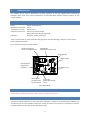
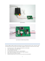
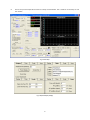
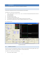
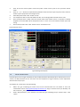
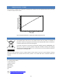
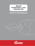
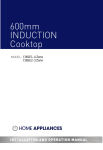
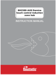
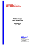
IJ Instruments Ltd.
IJ-7 DEMO MODULE
MANUAL AND QUICK-START GUIDE
MANUAL VERSION 1.3
FOR SOFTWARE VERSION 1.4, IJ-6 HARDWARE REVISION C, IJ-7 HARDWARE REVISION D.
1
TABLE OF CONTENTS
2
Introduction ............................................................................................................................................. 3
3
Specifications/Pinout ................................................................................................................................ 3
4
Safety ....................................................................................................................................................... 3
5
FCC Notice ................................................................................................................................................ 3
6
Initial Setup .............................................................................................................................................. 4
6.1
Hardware ........................................................................................................................................ 4
6.2
Software.......................................................................................................................................... 5
7
Experiments.............................................................................................................................................. 7
7.1
PID Control ...................................................................................................................................... 7
7.2
Manual Control................................................................................................................................ 7
7.3
Gain scheduling ............................................................................................................................... 8
7.4
Relay usage ..................................................................................................................................... 9
7.5
File Logging.................................................................................................................................... 10
7.6
Temperature Program ................................................................................................................... 10
8
Temperature vs. Power ........................................................................................................................... 12
9
Product Disposal Instructions .................................................................................................................. 12
10
Contact/Support ................................................................................................................................ 12
11
Revision History ................................................................................................................................. 13
2
2
INTRODUCTION
This module can be used to demonstrate the basic operation of the IJ-6 software-based temperature
controller. After initial setup, several experiments are described which explore different functions of the
control software.
3
SPECIFICATIONS/PINOUT
Power:
Maximum temperature:
Temperature rise rate:
Controller connections:
Indicators:
12VDC, 0.5A maximum.
120°C
Approx. 1°C/s
SSR input to operate heater
Relay input to operate warning buzzer
DC power, heating, and buzzer
There is a small sticker on top of the buzzer saying “Remove seal after washing”. Leave this in place since it
helps to quieten the buzzer.
Fig. 1 shows various features of the module.
Aluminium thermal
block + hea!ng element
Hea!ng LED
(lights when heater is on)
DC power LED
2
DC power input
2
3
Connec!ons to
temperature
controller
1
Off/on switch
1
4
+
Alarm buzzer
(on when relay
input is closed)
Alarm LED
(lights when buzzer
is on)
Fig. 1: Module layout
4
SAFETY
Please observe all safety precautions listed in the IJ-6 controller user manual.
5
FCC NOTICE
This device complies with part 15 of the FCC Rules. Operation is subject to the following two conditions: (1)
This device may not cause harmful interference, and (2) this device must accept any interference received,
including interference that may cause undesired operation.
3
This equipment has been tested and found to comply with the limits for a Class B digital device, pursuant to
part 15 of the FCC Rules. These limits are designed to provide reasonable protection against harmful
interference in a residential installation. This equipment generates, uses and can radiate radio frequency
energy and, if not installed and used in accordance with the instructions, may cause harmful interference to
radio communications. However, there is no guarantee that interference will not occur in a particular
installation. If this equipment does cause harmful interference to radio or television reception, which can be
determined by turning the equipment off and on, the user is encouraged to try to correct the interference by
one or more of the following measures: —Reorient or relocate the receiving antenna. —Increase the
separation between the equipment and receiver. —Connect the equipment into an outlet on a circuit different
from that to which the receiver is connected. —Consult the dealer or an experienced radio/TV technician for
help.
6
INITIAL SETUP
It is assumed that the software (drivers and control) has already been installed & configured (see introduction
to Section 6 of the IJ-6 manual), and that the user is familiar with how to input data (Section 6.2.2) of the IJ-6
manual). Start with the software initially closed.
6.1
HARDWARE
With both the IJ-6 and IJ-7 switched off, connect them as follows (refer to Fig. 2).
1.
2.
3.
4.
5.
Plug the thermocouple into the socket on the IJ-6 controller. It can only be inserted one way because of
the different sizes of the pins. Insert the other end of the thermocouple fully into the hole in the small
aluminium block on the IJ-7 module. Do not force the thermocouple – the hole in the block is about
12mm deep.
Connect a shorting link as shown. This makes the controller use a local ground reference (see Section
8.2.3 of the IJ-6 manual for further details).
Connect the SSR output of the IJ-6 controller to the SSR input of the IJ-7 module, ensuring correct
polarity.
Connect the #2 relay output of the IJ-6 to the relay inputs of the IJ-7. Polarity is not important.
Lastly, connect the IJ-7 to a source of 12V power, capable of delivering at least 0.5A, and switch on both
the IJ-6 and IJ-7.
IJ-6 Temperature Controller
IJ-7 Demo Module
Shor!ng
link
+
1
4
2
3
2
1
Thermocouple
Fig. 2: Connection details
Photos of the initial setup are shown in Fig. 3 and Fig. 4.
4
From 12V power
Fig. 3: Overall view
Fig. 4: Closeup of IJ-7 module showing connections
6.2
SOFTWARE
Start the software. Adjust all values to those shown in Fig. 5, except the values for “Zero” and “Gain”, which
will already have been set during the initial software configuration (see Section 6.2.3 of the IJ-6 user manual).
1.
2.
3.
4.
5.
6.
7.
Set “Power Control” to “Off”. Choose 0.455 cycle time and click update.
Under “ADC Settings”, enter 1000 samples.
Choose a K-type thermocouple.
Un-check the three “Use?” boxes under “PID Parameters”.
Under “Setpoint & program control”, enter 20 in “Manual setpoint:”.
Set both relay control modes to “Manual”.
Set graphical display values to those shown in Fig. 6 and click “Reset display”.
5
8.
Ensure the process temperature shown is initially around 20-30°C. Use a small fan if necessary to cool
the module.
Fig. 5: Initial setup
Fig. 6: Graphical display settings
6
7
EXPERIMENTS
Here are some experiments to try. Feel free to try different parameters.
7.1
PID CONTROL
Demonstrates using full PID control to hold the temperature at the setpoint.
Set software as in initial setup. Do the following:
1.
2.
3.
4.
5.
6.
Under “PID parameters”, enter Kp = 30, Ti = 25, Td = 4 into the three PID parameter boxes and tick all
three “Use?” boxes.
Click “Reset display”.
Set “Power Control” to “PID”.
Enter 60 in the “Manual setpoint:” box.
The temperature should start rising and stabilise at 60°C after a few minutes.
Once done, set “Power Control” to “Off” and allow the module to cool, or use a fan.
Fig. 7 shows the result.
Fig. 7: PID control example
7.2
MANUAL CONTROL
Use PI-only control to hold temperature steady at a setpoint and then switch to manual power mode. This is
useful, for example, in open-loop tuning (see Section 7.2.2 of the IJ-6 manual).
Set software as in initial setup. Do the following:
1.
Enter 40 into “Manual setpoint:”.
7
2.
3.
4.
5.
6.
7.
Enter 20 into the manual power control box (under “Power control”) but do not yet select manual
mode.
Enter Kp = 3, Ti = 40 into the respective PID parameter boxes and tick only the top two “Use?” boxes to
enable only the proportional and integral terms.
Select PID power mode under “Power control”.
The temperature will increase and stabilise at 40°C. The resulting power should be around 7.5%.
Once the temperature is stable, select the manual mode under “Power control”. The power is instantly
stepped to a constant 20% and the temperature rises in a curve. This curve could be used for open-loop
tuning.
Once finished, select “Off” under “Power control” and allow to cool.
Fig. 8 shows the result.
Fig. 8: Switching to manual power
7.3
GAIN SCHEDULING
Demonstrates how to use gain scheduling to vary the PID parameters with temperature. Note that, for the IJ-7
module, the PID parameters do not vary much over the temperature range of interest, but this experiment
demonstrates the principle.
Set software as in initial setup. Do the following:
1.
2.
Obtain the gain scheduling file either from the CD enclosed with the IJ-6 module or from the
“Downloads” section of http://www.eyejayinstruments.com. Copy or save the file to your Desktop. The
file is called “IJ-7_Gain_Schedule.txt”.
Under “PID parameters”, click “Load file” and select the gain scheduling file you saved in step 1. Click
“Open”.
8
3.
4.
5.
6.
7.
8.
Under “PID parameters”, enter 0.6, 0.5, 0.125 into the three “GS factors” boxes. These are the gain
scheduling factors which will be used to calculate the PID parameters from the critical gain and period
stored in the gain scheduling file. These are the standard Ziegler-Nichols factors and result in a rapid
response with some overshoot.
Under “PID parameters”, tick all three “Use?” boxes. Tick “Enable gain scheduling”.
Under “Power control”, switch to “PID”.
Enter 60 into “Manual setpoint:”.
The temperature will begin to rise. Notice how the PID parameters vary slightly as the temperature
changes.
Once finished, select “Off” under “Power control” and allow to cool.
Fig. 9 shows the result.
Fig. 9: Gain scheduling result
7.4
RELAY USAGE
Demonstrates how to control the general-purpose relay outputs, specifically #2, which is connected to the
buzzer on the IJ-7 module.
Set software as in initial setup. Do the following:
1.
2.
3.
Under “Relay 2”, use the ON/OFF buttons to manually switch the relay. Note how the indicator in the
software, the corresponding LED on the IJ-6 front panel, and the buzzer + alarm LED on the IJ-7 module
all act together.
Switch Relay 2 off.
To experiment with temperature control of the relay output, choose “Temperature” under “Relay 2” to
select the temperature-controlled mode.
9
4.
5.
6.
7.
Under “Relay 2”, configure the boxes so they read “Less than……50……and…..greater than……40”, as
shown in Fig. 10. This will turn Relay 2 (and hence the buzzer) on when the temperature is between
40°C and 50°C.
Now enter 50 in the “Manual” box under “Power control” and enable the manual mode to start
heating.
As the temperature rises through the 40-50°C range, note how the relay is automatically switched on.
Turn the power “Off” and allow the module to cool. Again, on cooling, the relay switches on in the 4050°C range.
Fig. 10 shows the relay configuration for the temperature-controlled mode.
Fig. 10: Relay settings for temperature control
7.5
FILE LOGGING
Demonstrates how to log data to file.
Set software as in initial setup. Do the following:
1.
2.
3.
4.
5.
6.
Under “Logging”, click “Browse” and choose an output file to save data to. For example, save data as
“output.txt” on the Desktop. Make sure to enter the extension “.txt” since the format will be tabdelimited text. Click “Save”.
Under “Logging”, ensure all checkboxes are ticked. This will save all possible variables to file.
Under “Logging”, click “Start” to start recording data to file.
To record something of interest, enter 50 in the “Manual” box under “Power control” and enable
manual mode. The temperature will start rising.
After a while, turn the power “Off”.
Under “Logging”, click “Stop” to stop the logging. You can now open the log file and examine it.
If “Start” is clicked again, more data will be appended to the existing log file. To erase the log file, click “Clear
file”.
7.6
TEMPERATURE PROGRAM
This will take about 35 minutes to run and will demonstrate a temperature profile program.
Set software as in initial setup. Do the following:
1.
2.
3.
4.
5.
6.
Obtain the example program file either from the CD enclosed with the IJ-6 module or from the
“Downloads” section of http://www.eyejayinstruments.com. Copy or save the file to your Desktop. The
file is called “IJ-7_Example_Program.txt”.
Under “Setpoint & program control”, click “Load program” and choose the file you saved in step 1. Click
“Open”.
Load the gain scheduling file as described in Section 7.3.
Under “PID parameters”, enter 0.6, 0.5, 0.125 in the three “GS factors” boxes.
Under “PID parameters”, tick all three “Use?” boxes and tick “Enable gain scheduling”.
Under both “Relay 1” and “Relay 2”, set the control mode to “Programmed”.
10
7.
8.
9.
10.
11.
12.
13.
14.
15.
16.
17.
18.
19.
Under the graphical display settings, set the maximum time to 45 minutes, upper min/max temperature
range to 30°C – 80°C, and the #X gridlines to 11. Click “Reset display”.
Under “Power control”, switch to “PID”.
Under “Setpoint & program control”, click “Start” to start running the program. The setpoint
temperature is now under control of the external program.
Temperature will be held constant at 40°C for 10 minutes.
Relay 1 is then turned on (only the indicator will light, since the relay 1 output is not connected to
anything).
Temperature will rise to 70°C over the next 15 minutes.
Relay 1 is turned off.
Temperature will be held constant at 70°C for 5 minutes.
Relay 2 (and the buzzer) is turned on. The program pauses and waits for the user to resume it.
Click “Start” again to resume the program.
Temperature will fall to 60°C over the next 5 minutes.
Relay 2 (and the buzzer) is turned off.
The program stops and the temperature falls naturally.
Fig. 11 shows the result.
Fig. 11: Example program
11
8
TEMPERATURE VS. POWER
Fig. 12 shows the steady-state temperature reached by the module versus the applied heater power, assuming
an ambient temperature of 20°C.
130
Steady-state temperature (°C)
120
110
100
90
80
70
60
50
40
30
20
10
0
0
10
20
30
40
50
Power (%)
Fig. 12: Steady-state temperature vs. applied power (ambient temperature 20°C)
9
PRODUCT DISPOSAL INSTRUCTIONS
The symbol shown here and on the product means that the product is classified as
Electrical or Electronic Equipment and should not be disposed with other household or
commercial waste at the end of its working life.
The Waste of Electrical and Electronic Equipment (WEEE) Directive (2002/96/EC) has
been put in place to recycle products using best available recovery and recycling
techniques to minimize the impact on the environment, treat any hazardous substances
and avoid the increasing landfill.
When you have no further use for it, please dispose of the product as per your local authority’s recycling
processes. Business users should ensure that this product is not mixed with other commercial waste for
disposal.
10
CONTACT/SUPPORT
Dr. Lindsay Robert Wilson,
IJ Instruments Ltd.,
73 Harburn Road,
West Calder,
West Lothian,
EH55 8AT,
UK.
Web: http://www.eyejayinstruments.com
Email: [email protected]
12
11
REVISION HISTORY
v1.3 (15/04/13):
v1.2 (19/11/12):
v1.1 (02/07/12):
v1.0 (27/06/12):
Updated screenshots to match latest software version
Updated to refer to latest version of PCB
Modifications to setup section
Initial
13