1
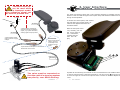
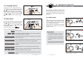
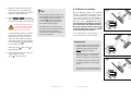
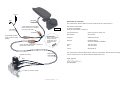
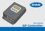
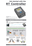
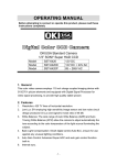
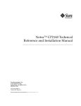
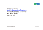
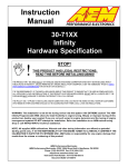
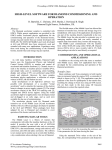
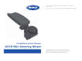
Installation & User Manual GP1R Mini Steering Wheel ver. 1 (080306) Art. nr: 630018 The most recent version of this manual can be downloaded from www.svab.se Installation & User Manual GP1R Mini Steering Wheel This work is protected by the Copyright Act and may not be copied, distributed or amended. Failure to comply with this Act can result in prosecution and fines, imprisonment or an obligation to pay compensation to the author/owner. Table of Contents 1. Introduction 1. Introduction 4 1.1 What is a GP1R Mini Steering Wheel? 1.1 What is a GP1R Mini Steering Wheel? .................................. 4 1.2 Operating an installed and configured GP1R ......................... 5 1.3 Summary of GP1R’s installation and configuration ................. 5 2. Installation 6 3. User Interface 8 The GP1R Mini Steering Wheel complements your equipment’s original steering system with a smaller steering wheel. The system is comprised of two units: the armrest-mounted steering wheel with built-in electronic steering and a hydraulic valve installed parallel to the equipment’s steering orbital. The GP1R is quite useful when used on equipment which is quite frequently steered, like forklifts, lawn mowers and tractors, and is used to ease strain on the driver’s shoulders and arms. With the GP1R’s adjustable steering sensitivity, the driver can customize steering with a personal sensitivity level. 2.1 Electrical installation ......................................................... 6 3.1 Language Setup ............................................................... 9 3.2 Main Menu ...................................................................... 9 4. System Setup 4.1 4.2 4.3 4.4 4.5 4.6 10 The manual describes how you mount and install your GPR1 system. The installation is done in two steps, first the hydraulic and the electrical connection, then system calibration for the equipment in question. Start level ......................................................................10 Measure cylinder .............................................................12 Wheel revolutions............................................................13 Change direction .............................................................13 Activation signal..............................................................13 Pump start signal ............................................................13 5. Trouble Shooting Arm 14 Activation button with indicator (green LED). Table of Contents 3 4 Introduction res t( op tio na le qu ip m en t) 1.2 Operating an installed and configured GP1R To activate the GP1R, hold in the activation button approx. one second. The activation indicator will then beep and light up. Inactivate by pressing the activation button again and the system is inactivated immediately. 2. Installation 1.3 Summary of GP1R’s installation and configuration 1. Mount the GP1R to the chair and then install the wheel and pilot valve hydraulically and electrically. 2. Select the language on start-up. (See section 3.1 to change language.) 3. The GP1R mini steering wheel must never be active while driving longer distances. Activate GP1R steering by holding down the activation button for approx. one second. Make sure the GP1R steers in the correct direction. Otherwise switch the direction of the DIN (Hirshman) contact on the directional control valve. 4. Follow the instructions in section 4.1 to set the start level. 5. Never start a vehicle or mini steering system without ALL hydraulic and electronic systems correctly installed. Follow the instructions in section 4.2 for ”Measure cylinder”. The GP1R mini steering wheel is now ready for use! 2.1 Electrical installation Assembly instructions are not adapted to any specific equipment or manufacture. The following is a general overview for the electrical installation of the GP1R mini steering wheel. Make sure that all wires are stripped accordingly and that there is no risk of the wires getting jammed in foldable armrests, doors or hatches. Finish assembly by connecting the 9-30V supply voltage to the brown wire. The wire must be protected by a 5 A fuse and not exceed 3 meters. Wire thickness must be at least 2x1 mm. The white wire is grounded to the equipment chassis. The wire must not exceed 3 meters. (For electric trucks an insulated converter should be used). 4 1 3 2 Connector: 1 – Activation indicator 2 – Pump start 3 – GND 4 – IN1 Failure to follow these instructions may lead to personal injury and/or damage to the vehicle! Tip: Make sure the (Hirshman) connectors are securely seated to keep out moisture, dust and dirt. Introduction 5 6 Installation ? The GP1R must never be used while in transport mode. The activation signal can be used to prevent this. The GP1R mini steering wheel has a user interface consisting of a display and three buttons. These are used during the initial system setup and therefore hidden from view during normal operation. + 9-30V Fuse 5A GND PN: 147146 3. User Interface To access the control panel, first remove the side plate (torx screws) which is located on the opposite side from the activation button. PN: 147145 4-pole Deutsch waterproof connector female (Activation signal) e.g. speed restriction, warning light and pump start. 2-pole Deutsch waterproof connector supply voltage. PN: 147450 Accessories: Spare 4-pole male, used to connect eventually extra functions to the GP1R. With the side plate removed, carefully pull out the circuit board a few centimeters, exposing the buttons and display. 6-pole Deutsch waterproof connector to directional control valve. Magnet wire PN: 147144-2 3 2 1 Valve for steering wheels. The valve must be connected so that the vehicle’s steering system has priority over GP1R steering. Installation 7 Symbols for the following are marked on the circuit board itself. The middle button is used to select/confirm a particular alternative. The arrow keys and are used to move through the various menu options and to increase or decrease a particular value. 8 User Interface 3.1 Language Setup 4. System Setup 2 sec. Language can be changed after the initial system set up by pressing both the + at the same time for about two seconds. The language menu appears when released. Choose language with and and to confirm. This manual assumes English as the selected language. This chapter describes the GP1R mini steering wheel’s system setup. How to access and navigate the menu system is dealt with in the previous chapter, User Interface. Language English 4.1 Start level 3.2 Main Menu x3 To open the main menu, press and hold the while at the same time pressing the three times. Use and to browse the menu and to confirm a selected alternative. To exit the menu, choose Return. While turning the steering wheel slowly, a default signal is sent via the pilot valve to the vehicle’s steering wheel. This signal is called the start level. If the start level is sufficient, the vehicle’s wheels will now begin to move at their lowest velocity. Meny: Return = If start level is too high, then a small turn of the GP1R makes the vehicle’s wheels start with a jerk. The main menu alternatives: Return – Exit the menu. Important! Start level – The electric current level where the wheels respond to the steering wheels movement. Measure cylinder – Customizes the GP1R system to a specific vehicle, based on the start level. Wheel revolutions – No. of revolutions required by the GP1R to turn the vehicle’s wheels from full left to full right position. Change direction – Changes the direction that the GP1R steers the vehicle’s » The GP1R’s Start Level must be setup before ”Measure Cylinder”. » To adjust levels the system must be turned ON with the activation button. » The equipment’s wheels should be jacked up to achieve best results. = If start level is too low, then the GP1R requires more turning before the vehicle’s wheels will move. = wheels. Activation signal – Optional function, e.g. warning light or point locking. = Pump start signal – Signal for electric vehicles where the hydraulic pump is only active while the vehicle is ON. Information – Firmware version, serial number and stored error mes- With a correct start level the vehicle’s wheels will sages. respond smoothly to the GP1R . User Interface 9 10 System Setup 1. 2. Make sure that the vehicle’s steering wheel is in its middle position, that is with approx. the same distance in both directions. Select Start level in the main menu. A warning will be shown that the system will begin self-operation. To avoid personal injury or equipment damage, make sure that the equipment’s wheel area is not obstructed! In the following menus, the GP1R itself may be used to increase or decrease levels. If a level is too high, then the vehicle’s steering wheel will begin turning immediately after pressing . Be prepared to decrease the level. Select Yes with and press begin adjustment. 3. 4.2 Measure cylinder Tip: » If the vehicle’s wheels reach their final position during the setup, but more adjustment is necessary, quit with , exit the menu and turn the steering wheel back to the middle position again. » The best way to correctly setup the start level is by beginning at a low value and then slowly increasing until the wheels begin to move (very slowly). (1). During ”Measure cylinder” the steering cylinder is calibrated. If not done correctly, the system may not function correctly in both directions or the number of steering revolutions may not correspond with the setup. Therefore it is important that the installation technician is observant and marks the three steering wheel positions with the precisely when they occur according to the following description. The related steps in this process (1, 2, 3) are shown on the GP1R display. (2). Important! » Because GP1R ”Measure cylinder” is dependent on the Start Level, the Start Level must be setup before ”Measure cylinder”. to Increase the level slowly until the wheels begin to move. Press to quit and save. » If the Start level is changed after ”Measure cylinder”, then a new ”Measure cylinder” must be done. » To adjust levels the system must be turned ON with the activation button. » The equipment’s wheels should be jacked up to achieve best results. System Setup 11 12 System Setup (3). 1. Select Measure cylinder in the main menu. 2. The system will warn that consequential steering follows. To avoid personal injury or equipment damage, make sure that the equipment’s wheel area is not obstructed! Select Yes with 3. 4. to continue. The wheels will begin to steer themafter the wheels selves. Press have reached their first final position (1). The wheels will first pause, then steer in the opposite direction. Again, press when the wheels reach the final position (2). After the last cycle has run, press when the wheels reach the final position (3). The calibration is now completed. Exit with Return. Check that the GP1R makes the same number of revolutions in both directions and that this corresponds to the vehicle’s wheel position. The GP1R’s default is four revolutions from full right to full left position. If you would like to change this, continue to the next section ”4.3 Wheel revolutions”. If you get an equal number of revolutions in both directions, then ”Measure cylinder” is completed. If this is not the case, repeat the ”Measure cylinder” from step 1. ! 4.3 Wheel revolutions Wheel revolutions is measured as the number of revolutions or turns of the steering wheel, which is necessary to move the vehicle’s wheels from full right to full left position. The default setting is four revolutions (40). This means that it takes four turns of the GP1R to move the vehicle’s wheels from full right to the full left position. See it as the GP1R’s ”sensitivity”. 4.4 Change direction The ”Change direction” setup means that the direction of the mini steering wheel can be changed if the directional control valve is connected incorrectly. However, it is advised to switch the direction of the DIN (Hirshman) contact instead, so that in the case of a reset of the preferences, the system will steer in the correct direction. The GP1R can, as with the other SVAB GP units, recognize many system errors. When an error is registered, a four-digit code is displayed. System error The system has two microprocessors which monitor one another. Therefore many different errors can be detected. Type: System Setup 13 Action: Memory error. Contact SVAB 71XX A microprocessor communication error. Contact SVAB Outport error The system can recognize various outport errors, e.g. a loose or bad contact. Type: Cause and effect: Action: 3011 Short circuit on the proportional outport. Check if the wiring is correctly installed and for possible wire damage. 3111 Failure on Out1 (Steering speed). Check for possible wire damage and that all connectors are properly inserted. 3316 Short circuit or overloading of Out6/magnet connectors 2 on the pilot valve. (Steering direction). Check for possible wire damage. To activate an outport, select the main menu and exit. 3317 Short circuit or overloading of Out7/magnet connectors 3 on the pilot valve. (Steering direction). Check for possible wire damage. To activate an outport, select the main menu and exit. 3318 Short circuit or overloading of Out8. Check for possible wire damage. To acti(Activation signal). vate an outport, select the main menu and exit. 3319 Short circuit or overloading of Out9. Check for possible wire damage. To acti(Pump start signal). vate an outport, select the main menu and exit. 3416 Failure on Out6/magnet connectors 2 on the pilot valve. (Steering direction). Check that all connectors are properly inserted and for possible wire damage. 3417 Failure on Out7/magnet connectors 3 on the pilot valve. (Steering direction). Check that all connectors are properly inserted and for possible wire damage. 3418 Failure on Out8. (Activation signal). Check that all connectors are properly inserted and for possible wire damage. 3419 Failure on Out9. (Pump start signal). Check that all connectors are properly inserted and for possible wire damage. 4.6 Pump start signal Pump start signal is an extra output for vehicles that require an activation signal to start a hydraulic pump, primarily for electrical vehicles where the pump only works while the vehicle is active. Cause: 70XX 4.5 Activation signal Activation signal is an optional extra output that is active when the system is in use, often used to turn on and off a warning light or to restrict the vehicle’s speed while the GP1R is in use. 5. Trouble Shooting 14 Trouble Shooting + 9-30V GND Declaration of conformity PN: 147145 The manufacturer declares that the product complies with the requirements in: 4-pole female Deutsch waterproof connector e.g. warning light and pump start. PN: 147146 PN: 147450 Out8/Out9 2-pole Deutsch waterproof connector supply voltage. Accessories: Spare 4-pole male, used to connect eventually extra functions to the GP1R. 6-pole Deutsch waterproof connector to directional control valve. Magnet connectors. EMC directive 89/336 EEG CE directive 93/68 EEG Safety directive EN954-1 category 3 Type of Equipment: Control system for mobile use Brand Name: GP Controller Company: SVAB Hydraulik AB Address: Ulvsättersgatan 2 SE-694 91 Hallsberg, SWEDEN Phone: Fax: +46 582 15230 +46 582 15232 E-mail: [email protected] The manufacturer within EU/EES declares under sole responsibility that this product complies with the requirements in the aforementioned standard directives. Magnet wire PN: 147144-2 SVAB Hydraulik Out7 3 Out6 Kent Bengtsson 2 Out1 1 Valve for steering wheels. Trouble Shooting 15 Notes: Notes: Ulvsättersgatan 2 SE-694 91 Hallsberg, SWEDEN PHONE: +46 582 15230 FAX: +46 582 15232 www.svab.se [email protected]