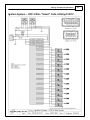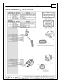
1
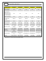
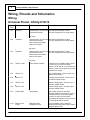
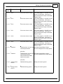
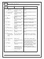
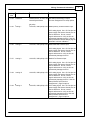
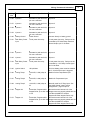
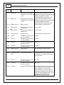
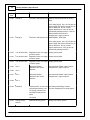
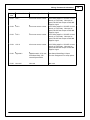
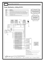
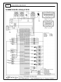
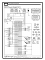
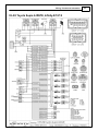
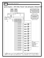
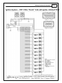
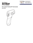
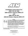
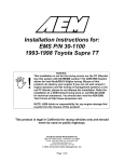
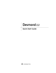
Instruction
Manual
30-71XX
Infinity
Hardware Specification
STOP!
THIS PRODUCT HAS LEGAL RESTRICTIONS.
READ THIS BEFORE INSTALLING/USING!
THIS PRODUCT MAY BE USED SOLELY ON VEHICLES USED IN SANCTIONED COMPETITION WHICH MAY NEVER BE USED UPON A
PUBLIC ROAD OR HIGHWAY, UNLESS PERMITTED BY SPECIFIC REGULATORY EXEMPTION. (VISIT THE “EMISSIONS” PAGE AT HTTP://
WWW.SEMASAN.COM/EMISSIONS FOR STATE BY STATE DETAILS.)
IT IS THE RESPONSIBILITY OF THE INSTALLER AND/OR USER OF THIS PRODUCT TO ENSURE THAT IT IS USED IN COMPLIANCE WITH
ALL APPLICABLE LAWS AND REGULATIONS. IF THIS PRODUCT WAS PURCHASED IN ERROR, DO NOT INSTALL AND/OR USE IT. THE
PURCHASER MUST ARRANGE TO RETURN THE PRODUCT FOR A FULL REFUND.
THIS POLICY ONLY APPLIES TO INSTALLERS AND/OR USERS WHO ARE LOCATED IN THE UNITED STATES; HOWEVER CUSTOMERS
WHO RESIDE IN OTHER COUNTRIES SHOULD ACT IN ACCORDANCE WITH THEIR LOCAL LAWS AND REGULATIONS.
WARNING: This installation is not for the tuning novice! Use this system with EXTREME caution! The AEM
Infinity Programmable EMS allows for total flexibility in engine tuning. Misuse or improper tuning of this
product can destroy your engine! If you are not well versed in engine dynamics and the tuning of engine
management systems DO NOT attempt the installation. Refer the installation to an AEM-trained tuning
shop or call 800-423-0046 for technical assistance.
NOTE: All supplied AEM calibrations, Wizards and other tuning information are offered as potential
starting points only. IT IS THE RESPONSIBILITY OF THE ENGINE TUNER TO ULTIMATELY CONFIRM IF THE
CALIBRATION IS SAFE FOR ITS INTENDED USE. AEM holds no responsibility for any engine damage that
results from the misuse or mistuning of this product!
AEM Performance Electronics
AEM Performance Electronics, 2205 126th Street Unit A, Hawthorne, CA 90250
Phone: (310) 484-2322 Fax: (310) 484-0152
http://www.aemelectronics.com
Instruction Part Number: 10-71XX-Hardware
Document Build 12/14/2015
Infinity Hardware Specification
Table of Contents
Hardware
.............................................................................................................................................................
1
Infinity
Hardware Specifications
.............................................................................................................................................................
3
ECU
Installation Dimensions Infinity-8/10/12
Wiring, Pinouts and Schematics
............................................................................................................................................................. 4
Wiring
.............................................................................................................................................................
4
Universal
Pinout, Infinity-8/10/12
.............................................................................................................................................................
16
Connector
Views Infinity-8/10/12
.............................................................................................................................................................
16
Example
System Schematics
Power
..........................................................................................................................................................18
Distribution, Infinity-8/10/12
Internal
..........................................................................................................................................................19
UEGO, Infinity-8/10/12
95..........................................................................................................................................................20
BMW E36 M3, Infinity-8/10/12
EVO
..........................................................................................................................................................21
VIII, Infinity-8/10/12
EVO
..........................................................................................................................................................22
IX Pinout, Infinity-8/10/12
93–98
..........................................................................................................................................................23
Toyota Supra 2JZGTE, Infinity-8/10/12
Ignition
..........................................................................................................................................................24
System – COP 2 Wire "Dumb" Coils with Ignitor, Infinity-8/10/12
Ignition
..........................................................................................................................................................25
System – COP 3 Wire "Dumb" Coils with Ignitor, Infinity-8/10/12
Ignition
..........................................................................................................................................................26
System – COP 3 Wire "Smart" Coils, Infinity-8/10/12
Ignition
..........................................................................................................................................................27
System – COP 4 Wire "Smart" Coils, Infinity-8/10/12
Ignition
..........................................................................................................................................................28
System – COP 5 Wire "Smart" Coils, Infinity-8/10/12
GM
..........................................................................................................................................................29
LS3 DBW Wiring, Infinity-8/10/12
© 2015 AEM Performance Electronics
Hardware
1
Hardware
Infinity Hardware Specifications
Specifications
Infinity-6
Infinity-8h
Infinity-8
Infinity-10
Infinity-812
Up to 6
Up to 8
Up to 8
Up to 10
Up to 12
Injectors, Low
Impedance
(Sequential)
6
N/A
8
10
12
Injectors High
Impedance
(Sequential)
Up to 6
Up to 8
8
10
12
Coils – 0–5V
Falling Edge
6
8
8
10
10
Connector Pins
80
80
129
129
129
Drive-by-Wire
Single
Single
Dual
Dual
Dual
H-Bridge
Channels
1
1
2
2
2
RS232 Channels*
1
1
1
1
1
CAN Channels
2
2
2
2
2
2-Stroke Engines
Yes
Yes
Yes
Yes
Yes
4-Stroke Engines
Yes
Yes
Yes
Yes
Yes
Knock Control
2-Channel
2-Channel
2-Channel
2-Channel
2-Channel
Analog Voltage
Inputs
Up to 9
Up to 9
Up to 17
Up to 17
Up to 17
Analog Temp
Inputs
Up to 3
Up to 3
Up to 6
Up to 6
Up to 6
VR/Mag Inputs
Up to 4
Up to 4
Up to 6
Up to 6
Up to 6
Digital Inputs
Up to 8
Up to 6
Up to 8
Up to 8
Up to 8
Internal
Wideband UEGO
Controller
1
1
2
2
2
High Side Outputs
1
1
Up to 2
Up to 2
Up to 2
Low Side Outputs
8
6
10
10
10
Cylinders
© 2015 AEM Performance Electronics
2
Infinity Hardware Specification
Specifications
Infinity-6
Infinity-8h
Infinity-8
Infinity-10
Infinity-812
4-Wire Stepper
Motor Control
Yes
Yes
Yes
Yes
Yes
Boost Control
(RPM, Time, Gear,
VSS, Switch Input,
Flex Fuel Content
Yes
Yes
Yes
Yes
Yes
Engine Protection
Yes
Yes
Yes
Yes
Yes
Up to 2
Up to 2
Up to 4
Up to 4
Up to 4
Launch Control
Yes
Yes
Yes
Yes
Yes
Nitrous Control
Single Stage
Single Stage
Single Stage
Single Stage
Single Stage
Data Logging
Up to 64 GB
Up to 64 GB
Up to 64 GB
Up to 64 GB
Up to 64 GB
Traction Control
Up to 2-Wheel
Speed
Up to 2-Wheel
Speed
Up to 4-Wheel
Speed
Up to 4-Wheel
Speed
Up to 4-Wheel
Speed
Weather
Resistance
Yes, Sealed
Yes, Sealed
Yes, Sealed
Yes, Sealed
Yes, Sealed
Enclosure with
Enclosure with Enclosure with Enclosure with Enclosure with
IP67
IP67 Connectors IP67 Connectors IP67 Connectors IP67 Connectors
Connectors
Enclosure Dims
5.855"x5.55"x1. 5.855"x5.55"x1.
6.75"x6.00"x1.8
6.75"x6.00"x1.8" 6.75"x6.00"x1.8"
8"
8"
"
Weight
18.8 oz/476.27g 18.8 oz/476.27g
Variable Cam
Control
24oz/680g
24oz/680g
24oz/680g
**Dual use pins. Tx and Rx shared with 2 digital inputs.
© 2015 AEM Performance Electronics
Hardware
ECU Installation Dimensions Infinity-8/10/12
© 2015 AEM Performance Electronics
3
4
Infinity Hardware Specification
Wiring, Pinouts and Schematics
Wiring
Universal Pinout, Infinity-8/10/12
Infinity
Pin
C1-1
Hrdwr Ref.
Lowside 4
Hardware Specification
Notes
Lowside switch, 4A max, NO See Setup Wizard Page "Output
internal flyback diode.
Function Assignment" for setup options.
No pullup
C1-2
Lowside 5
Lowside switch, 4A max with See Setup Wizard Page "Output
internal flyback diode.
Function Assignment" for setup options.
Inductive load should NOT
have full time power.
No pullup
C1-3
Lowside 6
Lowside switch, 4A max with See Setup Wizard Page "Output
internal flyback diode.
Function Assignment" for setup options.
Inductive load should NOT
have full time power.
No pullup
C1-4
UEGO 1 Heat
Bosch UEGO controller
Lowside switch for UEGO heater control.
Connect to pin 4 of Bosch UEGO
sensor. NOTE that pin 3 of the Sensor is
heater (+) and must be power by a fused/
switched 12V supply.
C1-5
UEGO 1 IA
Trim Current signal. Connect to pin 2 of
Bosch UEGO sensor
C1-6
UEGO 1 IP
Pumping Current signal. Connect to pin
6 of Bosch UEGO sensor
C1-7
UEGO 1 UN
Nernst Voltage signal. Connect to pin 1
of Bosch UEGO sensor
C1-8
UEGO 1 VM
Virtual Ground signal. Connect to pin 5
of Bosch UEGO sensor.
C1-9
Flash Enable
10K pulldown
Not usually needed for automatic
firmware updates through Infinity Tuner. If
connection errors occur during update,
connect 12 volts to this pin before
proceeding with upgrade. Disconnect the
12 volts signal after the update.
C1-10
Battery Perm
Power
Dedicated power
management CPU
Full time battery power. MUST be
powered before the ignition switch input is
triggered (See C1-65).
© 2015 AEM Performance Electronics
Wiring, Pinouts and Schematics
Infinity
Pin
Hrdwr Ref.
Hardware Specification
Notes
C1-11
Coil 4
25 mA max source current
0-5V Falling edge fire. DO NOT connect
directly to coil primary. Must use an
ignitor OR CDI that accepts a FALLING
edge fire signal.
C1-12
Coil 3
25 mA max source current
0-5V Falling edge fire. DO NOT connect
directly to coil primary. Must use an
ignitor OR CDI that accepts a FALLING
edge fire signal.
C1-13
Coil 2
25 mA max source current
0-5V Falling edge fire. DO NOT connect
directly to coil primary. Must use an
ignitor OR CDI that accepts a FALLING
edge fire signal.
C1-14
Coil 1
25 mA max source current
0-5V Falling edge fire. DO NOT connect
directly to coil primary. Must use an
ignitor OR CDI that accepts a FALLING
edge fire signal.
C1-15
Coil 6
25 mA max source current
0-5V Falling edge fire. DO NOT connect
directly to coil primary. Must use an
ignitor OR CDI that accepts a FALLING
edge fire signal.
C1-16
Coil 5
25 mA max source current
0-5V Falling edge fire. DO NOT connect
directly to coil primary. Must use an
ignitor OR CDI that accepts a FALLING
edge fire signal.
C1-17
Lowside 2
Lowside switch, 4A max, NO See Setup Wizard Page "Output
internal flyback diode.
Function Assignment" for setup options.
No pullup
C1-18
Lowside 3
Lowside switch, 4A max with See Setup Wizard Page "Output
internal flyback diode.
Function Assignment" for setup options.
Inductive load should NOT
have full time power.
No pullup
C1-19
Analog Sensor
Ground
Dedicated analog ground
Analog 0-5V sensor ground
C1-20
Analog Sensor
Ground
Dedicated analog ground
Analog 0-5V sensor ground
© 2015 AEM Performance Electronics
5
6
Infinity
Pin
Infinity Hardware Specification
Hrdwr Ref.
Hardware Specification
Notes
C1-21
Crankshaft Position 10K pullup to 12V. Will work See Setup Wizard page Cam/Crank for
Sensor Hall
with ground or floating
options.
switches.
C1-22
Camshaft Position
Sensor 1 Hall
10K pullup to 12V. Will work See Setup Wizard page Cam/Crank for
with ground or floating
options.
switches.
C1-23
Digital 2
10K pullup to 12V. Will work See Setup Wizard page Cam/Crank for
with ground or floating
options.
switches.
C1-24
Digital 3
10K pullup to 12V. Will work See Setup Wizard page "Input Function
with ground or floating
Assignments" for setup options.
switches.
C1-25
Digital 4
10K pullup to 12V. Will work See Setup Wizard page "Input Function
with ground or floating
Assignments" for setup options.
switches.
C1-26
Digital 5
10K pullup to 12V. Will work See Setup Wizard page "Input Function
with ground or floating
Assignments" for setup options.
switches.
C1-27
Knock Sensor 1
Dedicated knock signal
processor
See Setup Wizard page Knock Setup for
options.
C1-28
Knock Sensor 2
Dedicated knock signal
processor
See Setup Wizard page Knock Setup for
options.
C1-29
EFI Main Relay
Switched Ground
Output
0.7A max ground sink for
external relay control
Will activate at key on and at key off
according to the configuration settings.
C1-30
Battery Ground
Battery Ground
Connect directly to battery ground
C1-31
CANL A
Dedicated High Speed CAN
Transceiver
Recommend twisted pair (one twist per
2") with terminating resistor. Contact
AEM for additional information.
C1-32
CANH A
Dedicated High Speed CAN
Transceiver
Recommend twisted pair (one twist per
2") with terminating resistor. Contact
AEM for additional information.
C1-33
Lowside 1
Lowside switch, 4A max with See Setup Wizard Page "Output
internal flyback diode.
Function Assignment" for setup options.
Inductive load should NOT
have full time power.
No pullup
© 2015 AEM Performance Electronics
Wiring, Pinouts and Schematics
Infinity
Pin
C1-34
Hrdwr Ref.
Lowside 0
Hardware Specification
Notes
Lowside switch, 4A max, NO See Setup Wizard Page "Output
internal flyback diode.
Function Assignment" for setup options.
No pullup
C1-35
Analog 7
12 bit A/D, 100K pullup to 5V Default primary Throttle Position input.
0-5V analog signal. Use +5V Out pins as
power supply and Sensor Ground pins as
the low reference. Do not connect
signals referenced to +12V as this can
permanently damage the ECU. See the
Setup Wizard Set Throttle Range page for
automatic min/max calibration.
C1-36
Analog 8
12 bit A/D, 100K pullup to 5V Default Manifold Pressure Input.
0-5V analog signal. Use +5V Out pins as
power supply and Sensor Ground pins as
the low reference. Do not connect
signals referenced to +12V as this can
permanently damage the ECU.
C1-37
Analog 9
12 bit A/D, 100K pullup to 5V Default Fuel Pressure Input.
0-5V analog signal. Use +5V Out pins as
power supply and Sensor Ground pins as
the low reference. Do not connect
signals referenced to +12V as this can
permanently damage the ECU.
C1-38
Analog 10
12 bit A/D, 100K pullup to 5V 0-5V analog signal. Use +5V Out pins as
power supply and Sensor Ground pins as
the low reference. Do not connect
signals referenced to +12V as this can
permanently damage the ECU. See the
Setup Wizard "Input Function
Assignments" page for options.
C1-39
Analog 11
12 bit A/D, 100K pullup to 5V 0-5V analog signal. Use +5V Out pins as
power supply and Sensor Ground pins as
the low reference. Do not connect
signals referenced to +12V as this can
permanently damage the ECU. See the
Setup Wizard "Input Function
Assignments" page for options.
© 2015 AEM Performance Electronics
7
8
Infinity
Pin
Infinity Hardware Specification
Hrdwr Ref.
Hardware Specification
Notes
C1-40
Analog 12
12 bit A/D, 100K pullup to 5V 0-5V analog signal. Use +5V Out pins as
power supply and Sensor Ground pins as
the low reference. Do not connect
signals referenced to +12V as this can
permanently damage the ECU. See the
Setup Wizard "Input Function
Assignments" page for options.
C1-41
+5V Sensor Power
Regulated, fused +5V supply Analog sensor power
for sensor power
C1-42
+5V Sensor Power
Regulated, fused +5V supply Analog sensor power
for sensor power
C1-43
Highside 1
0.7A max, High Side Solid
State Relay
See Setup Wizard page "Output Function
Assignment" for configuration options.
C1-44
Highside 0
0.7A max, High Side Solid
State Relay
See Setup Wizard page "Output Function
Assignment" for configuration options.
C1-45
Crankshaft Position Differential Variable
Sensor VR+
Reluctance Zero Cross
Detection
Crankshaft Position
Sensor VR-
See Setup Wizard page Cam/Crank for
options.
C1-47
Camshaft Position
Sensor 1 VR-
See Setup Wizard page Cam/Crank for
options.
C1-48
Camshaft Position
Sensor 1 VR+
Differential Variable
Reluctance Zero Cross
Detection
C1-49
VR+ 2
Differential Variable
Reluctance Zero Cross
Detection
See the Setup Wizard "Input Function
Assignments" page for options.
C1-50
VR- 2
C1-51
VR- 3
See the Setup Wizard "Input Function
Assignments" page for options.
C1-52
VR+ 3
Differential Variable
Reluctance Zero Cross
Detection
C1-53
DBW1 Motor -
5.0A max Throttle Control
Hbridge Drive
+12V to close.
C1-54
DBW1 Motor +
5.0A max Throttle Control
Hbridge Drive
+12V to open.
C1-55
Battery Ground
Power Ground
Connect directly to battery ground
C1-46
See Setup Wizard page Cam/Crank for
options.
See Setup Wizard page Cam/Crank for
options.
© 2015 AEM Performance Electronics
Wiring, Pinouts and Schematics
Infinity
Pin
Hrdwr Ref.
Hardware Specification
Notes
C1-56
Injector 6
Saturated or peak and hold,
3A max continuous
Injector 6
C1-57
Injector 5
Saturated or peak and hold,
3A max continuous
Injector 5
C1-58
Injector 4
Saturated or peak and hold,
3A max continuous
Injector 4
C1-59
Injector 3
Saturated or peak and hold,
3A max continuous
Injector 3
C1-60
Battery Ground
Power Ground
Connect directly to battery ground
C1-61
Main Relay Power
Input
12 volt power from relay
12 volt power from relay. Relay must be
controlled by EFI Main Relay Switched
Ground Output, pin C1-29 above.
C1-62
Injector 2
Saturated or peak and hold,
3A max continuous
Injector 2
C1-63
Injector 1
Saturated or peak and hold,
3A max continuous
Injector 1
C1-64
Main Relay Power
Input
12 volt power from relay
12 volt power from relay. Relay must be
controlled by +12V Relay Control signal
pin C1-29 above.
C1-65
Ignition Switch
10K pulldown
Full time battery power must be available
at C1-10 before this input is triggered.
C1-66
Analog Temp 1
12 bit A/D, 2.49K pullup to
5V
Default Coolant Temperature Input.
C1-67
Analog Temp 2
12 bit A/D, 2.49K pullup to
5V
Default Air Temperature Input.
C1-68
Analog Temp 3
12 bit A/D, 2.49K pullup to
5V
Normally used for Oil Temp input. See
the Setup Wizard "Input Function
Assignments" page for options.
C1-69
Stepper 2A
Automotive, Programmable
Be sure that each internal coil of the
Stepper Driver, up to 28V and stepper motor are properly paired with the
±1.4A
1A/1B and 2A/2B ECU outputs.
Supports Bi-Polar stepper motors only.
C1-70
Stepper 1A
Automotive, Programmable
Be sure that each internal coil of the
Stepper Driver, up to 28V and stepper motor are properly paired with the
±1.4A
1A/1B and 2A/2B ECU outputs.
Supports Bi-Polar stepper motors only.
© 2015 AEM Performance Electronics
9
10
Infinity
Pin
Infinity Hardware Specification
Hrdwr Ref.
Hardware Specification
Notes
C1-71
Stepper 2B
Automotive, Programmable
Be sure that each internal coil of the
Stepper Driver, up to 28V and stepper motor are properly paired with the
±1.4A
1A/1B and 2A/2B ECU outputs.
Supports Bi-Polar stepper motors only.
C1-72
Stepper 1B
Automotive, Programmable
Be sure that each internal coil of the
Stepper Driver, up to 28V and stepper motor are properly paired with the
±1.4A
1A/1B and 2A/2B ECU outputs.
Supports Bi-Polar stepper motors only.
C1-73
Battery Ground
Battery Ground
Connect directly to battery ground
C2-1
DBW2 Motor +
5.0A max Throttle Control
Hbridge Drive
+12V to open.
C2-2
DBW2 Motor -
5.0A max Throttle Control
Hbridge Drive
+12V to close.
C2-3
Battery Ground
Battery Ground
Connect directly to battery ground
C2-4
Injector 7
Saturated or peak and hold,
3A max continuous
Injector 7
C2-5
Injector 8
Saturated or peak and hold,
3A max continuous
Injector 8
C2-6
Injector 9
Saturated or peak and hold,
3A max continuous
Injector 9.
C2-7
Injector 10
Saturated or peak and hold,
3A max continuous
Injector 10.
C2-8
Battery Ground
Power Ground
Connect directly to battery ground.
C2-9
Main Relay Power
Input
12 volt power from relay
12 volt power from relay. Relay must be
controlled by +12V Relay Control signal,
pin C1-29 above.
C2-10
Injector 11
Saturated or peak and hold,
3A max continuous
Not used
C2-11
Injector 12
Saturated or peak and hold,
3A max continuous
Not used
C2-12
Analog 17
12 bit A/D, 100K pullup to 5V 0-5V analog signal. Use +5V Out pins as
power supply and Sensor Ground pins as
the low reference. Do not connect
signals referenced to +12V as this can
permanently damage the ECU. Normally
used as A/C Analog Request input. See
the Setup Wizard "Input Function
Assignments" page for options.
© 2015 AEM Performance Electronics
Wiring, Pinouts and Schematics
Infinity
Pin
Hrdwr Ref.
Hardware Specification
Notes
C2-13
Analog 18
12 bit A/D, 100K pullup to 5V 0-5V analog signal. Use +5V Out pins as
power supply and Sensor Ground pins as
the low reference. Do not connect
signals referenced to +12V as this can
permanently damage the ECU. Normally
used as DBW APP1. See the Setup
Wizard "Input Function Assignments"
page for options.
C2-14
Analog 19
12 bit A/D, 100K pullup to 5V 0-5V analog signal. Use +5V Out pins as
power supply and Sensor Ground pins as
the low reference. Do not connect
signals referenced to +12V as this can
permanently damage the ECU. Normally
used as DBW APP2. See the Setup
Wizard "Input Function Assignments"
page for options.
C2-15
Analog Temp 4
12 bit A/D, 2.49K pullup to
5V
Normally used as Charge Out
Temperature input. See the Setup Wizard
"Input Function Assignments" page for
options.
C2-16
Analog Temp 5
12 bit A/D, 2.49K pullup to
5V
Normally used as Airbox Temperature
input. See the Setup Wizard "Input
Function Assignments" page for options.
C2-17
Analog Temp 6
12 bit A/D, 2.49K pullup to
5V
Normally used as Fuel Temperature
input.See the Setup Wizard "Input
Function Assignments" page for options.
C2-18
Analog 13
12 bit A/D, 100K pullup to 5V Default Oil Pressure sensor input.
0-5V analog signal. Use +5V Out pins as
power supply and Sensor Ground pins as
the low reference. Do not connect
signals referenced to +12V as this can
permanently damage the ECU.
C2-19
Analog 14
© 2015 AEM Performance Electronics
12 bit A/D, 100K pullup to 5V 0-5V analog signal. Use +5V Out pins as
power supply and Sensor Ground pins as
the low reference. Do not connect
signals referenced to +12V as this can
permanently damage the ECU. See the
Setup Wizard "Input Function
Assignments" page for options.
11
12
Infinity
Pin
C2-20
Infinity Hardware Specification
Hrdwr Ref.
Analog 15
Hardware Specification
Notes
12 bit A/D, 100K pullup to 5V Default Exhaust Backpressure Sensor
Input
0-5V analog signal. Use +5V Out pins as
power supply and Sensor Ground pins as
the low reference. Do not connect
signals referenced to +12V as this can
permanently damage the ECU. See the
Setup Wizard "Input Function
Assignments" page for options.
C2-21
Analog 16
12 bit A/D, 100K pullup to 5V Default DBW1_TPSB input.
0-5V analog signal. Use +5V Out pins as
power supply and Sensor Ground pins as
the low reference. Do not connect
signals referenced to +12V as this can
permanently damage the ECU.
C2-22
+5V Sensor Power
Regulated, fused +5V supply Analog sensor power
for sensor power
C2-23
+5V Sensor Power
Regulated, fused +5V supply Analog sensor power
for sensor power
C2-24
+5V Sensor Power
Regulated, fused +5V supply Analog sensor power
for sensor power
C2-25
VR+ 5
See the Setup Wizard "Input Function
Assignments" page for options.
C2-26
VR- 5
Differential Variable
Reluctance Zero Cross
Detection
C2-27
VR- 4
Differential Variable
Reluctance Zero Cross
Detection
See the Setup Wizard "Input Function
Assignments" page for options.
C2-28
VR+ 4
C2-29
Lowside 9
Lowside switch, 4A max with See Setup Wizard Page "Output
internal flyback diode, 2.2K
Function Assignment" for setup options.
12V pullup. Inductive load
should NOT have full time
power.
12V pullup
C2-30
Analog Sensor
Ground
Dedicated analog ground
Analog 0-5V sensor ground
© 2015 AEM Performance Electronics
Wiring, Pinouts and Schematics
Infinity
Pin
Hrdwr Ref.
Hardware Specification
Notes
C2-31
Analog Sensor
Ground
Dedicated analog ground
Analog 0-5V sensor ground
C2-32
Analog Sensor
Ground
Dedicated analog ground
Analog 0-5V sensor ground
C2-33
Analog 20
12 bit A/D, 100K pullup to 5V 0-5V analog signal. Use +5V Out pins as
power supply and Sensor Ground pins as
the low reference. Do not connect
signals referenced to +12V as this can
permanently damage the ECU.
C2-34
Analog 21
12 bit A/D, 100K pullup to 5V 0-5V analog signal. Use +5V Out pins as
power supply and Sensor Ground pins as
the low reference. Do not connect
signals referenced to +12V as this can
permanently damage the ECU. Normally
used as 3 Step Enable Switch input.
See the Setup Wizard "Input Function
Assignments" page for options.
C2-35
Analog 22
12 bit A/D, 100K pullup to 5V 0-5V analog signal. Use +5V Out pins as
power supply and Sensor Ground pins as
the low reference. Do not connect
signals referenced to +12V as this can
permanently damage the ECU. See the
Setup Wizard "Input Function
Assignments" page for options.
C2-36
Analog 23
12 bit A/D, 100K pullup to 5V Default Charge Out Pressure Sensor
Input
0-5V analog signal. Use +5V Out pins as
power supply and Sensor Ground pins as
the low reference. Do not connect
signals referenced to +12V as this can
permanently damage the ECU. See the
Setup Wizard "Input Function
Assignments" page for options.
C2-37
Digital 6
© 2015 AEM Performance Electronics
No pullup. Accepts 12V
switch inputs
Input can be assigned to different pins.
See Setup Wizard page Input Function
Assignments for input mapping options.
13
14
Infinity
Pin
Infinity Hardware Specification
Hrdwr Ref.
Hardware Specification
Notes
C2-38
Digital 7
No pullup. Accepts 12V
switch inputs
See ClutchSwitch 1-axis table for setup
options. Input can be assigned to
different pins. See Setup Wizard page
Input Function Assignments for input
mapping options.
C2-39
Battery Ground
Battery Ground
Connect directly to battery ground
C2-40
Battery Ground
Battery Ground
Connect directly to battery ground
C2-41
CanH B
Dedicated High Speed CAN
Transceiver
Not used
C2-42
CanL B
Dedicated High Speed CAN
Transceiver
Not used
C2-43
Lowside 8
Lowside switch, 4A max with See Setup Wizard Page "Output
internal flyback diode.
Function Assignment" for setup options.
Inductive load should NOT
have full time power.
12V pullup
C2-44
Lowside 7
Lowside switch, 4A max with See Setup Wizard Page "Output
internal flyback diode.
Function Assignment" for setup options.
Inductive load should NOT
have full time power.
No pullup
C2-45
UEGO 2 VM
Bosch UEGO Controller
C2-46
UEGO 2 UN
Nernst Voltage signal. Connect to pin 1
of Bosch UEGO sensor
C2-47
UEGO 2 IP
Pumping Current signal. Connect to pin
6 of Bosch UEGO sensor
C2-48
UEGO 2 IA
Trim Current signal. Connect to pin 2 of
Bosch UEGO sensor
C2-49
UEGO 2 HEAT
Lowside switch for UEGO heater control.
Connect to pin 4 of Bosch UEGO
sensor. NOTE that pin 3 of the Sensor is
heater (+) and must be power by a fused/
switched 12V supply.
C2-50
Battery Perm
Power
Dedicated power
management CPU
Virtual Ground signal. Connect to pin 5
of Bosch UEGO sensor.
Full time battery power. MUST be
powered before the ignition switch input is
triggered (See C1-65).
© 2015 AEM Performance Electronics
Wiring, Pinouts and Schematics
Infinity
Pin
Hrdwr Ref.
Hardware Specification
Notes
C2-51
Coil 7
25 mA max source current
0-5V Falling edge fire. DO NOT connect
directly to coil primary. Must use an
ignitor OR CDI that accepts a FALLING
edge fire signal.
C2-52
Coil 8
25 mA max source current
0-5V Falling edge fire. DO NOT connect
directly to coil primary. Must use an
ignitor OR CDI that accepts a FALLING
edge fire signal.
C2-53
Coil 9
25 mA max source current
0-5V Falling edge fire. DO NOT connect
directly to coil primary. Must use an
ignitor OR CDI that accepts a FALLING
edge fire signal.
C2-54
Coil 10
25 mA max source current
0-5V Falling edge fire. DO NOT connect
directly to coil primary. Must use an
ignitor OR CDI that accepts a FALLING
edge fire signal.
C2-55
Highside 2
Highside switch, 0.7A max,
Solid State Relay, NO
internal flyback diode.
See Setup Wizard Page "Output
Function Assignment" for setup options.
C2-56
Not used
Not used
Not used
© 2015 AEM Performance Electronics
15
16
Infinity Hardware Specification
Connector Views Infinity-8/10/12
Example System Schematics
Custom wiring harness projects should only be undertaken by experienced harness builders. If in doubt,
please contact AEM for recommendations.
For users wishing to build their own wiring harnesses from scratch, the following kits are available to help.
30-3701 Infinity-8/10/12 Plug & Pin Kit
Bare necessities to begin a custom wire harness design. Includes 73- and 56-pin Molex MX123 harness
connectors, terminals and sealing plugs, main relay and relay socket.
30-3702 Infinity-8/10/12 Mini-harness
This harness is intended to be used as a starting point by experienced harness builders. It saves time by including
basic power distribution features that can be expanded to suit many application requirements. It allows the harness
builder to populate the ECU connector with only the features needed by the application. Includes 100 96" preterminated leads.
30-3703 Infinity-8/10/12 Mini-harness
This harness is intended to be used as a starting point by experienced harness builders. It saves time by including
basic power distribution features that can be expanded to suit many application requirements. It allows the harness
builder to populate the ECU connector with only the features needed by the application.
© 2015 AEM Performance Electronics
Wiring, Pinouts and Schematics
17
30-3704 Infinity-6/8h Plug & Pin Kit
Bare necessities to begin a custom wire harness design. Includes 80-pin Molex MX123 harness connector,
terminals and sealing plugs, main relay and relay socket.
30-3805 Universal modular V8 harness system for Infinity-8/10 systems
The Infinity Universal Modular V8 Harness system consists of a universal core harness and optional application
specific extensions. It was designed with flexibility in mind. The harness system includes many features and it can
be used in many different applications.
30-3809 Universal modular V8 harness system for Infinity-6/8h systems
The Infinity Universal Modular V8 Harness system consists of a universal core harness and optional application
specific extensions. It was designed with flexibility in mind. The harness system includes many features and it can
be used in many different applications.
30-3705 Universal Mini Harness for Infinity-6/8h systems
This harness is intended to be used as a starting point by experienced harness builders. It saves time by including
basic power distribution features that can be expanded to suit many application requirements. It allows the harness
builder to populate the ECU connector with only the features needed by the application.
30-3706 Universal Mini Flying Lead for Infinity-6/8h systems
This harness is intended to be used as a starting point by experienced harness builders. It saves time by including
basic power distribution features that can be expanded to suit many application requirements.
The following schematics show examples for wiring a basic Infinity system. Examples are included for both Infinity6/8h and Infinity-8/10/12 hardware platforms. The power, ground and accessory relay sections of the following
schematics must be strictly followed to avoid inconsistent power sequencing and possible ECU damage.
© 2015 AEM Performance Electronics
18
Infinity Hardware Specification
Power Distribution, Infinity-8/10/12
© 2015 AEM Performance Electronics
Wiring, Pinouts and Schematics
Internal UEGO, Infinity-8/10/12
© 2015 AEM Performance Electronics
19
20
Infinity Hardware Specification
95 BMW E36 M3, Infinity-8/10/12
© 2015 AEM Performance Electronics
Wiring, Pinouts and Schematics
EVO VIII, Infinity-8/10/12
© 2015 AEM Performance Electronics
21
22
Infinity Hardware Specification
EVO IX Pinout, Infinity-8/10/12
© 2015 AEM Performance Electronics
Wiring, Pinouts and Schematics
93–98 Toyota Supra 2JZGTE, Infinity-8/10/12
© 2015 AEM Performance Electronics
23
24
Infinity Hardware Specification
Ignition System – COP 2 Wire "Dumb" Coils with Ignitor, Infinity-8/10/12
© 2015 AEM Performance Electronics
Wiring, Pinouts and Schematics
25
Ignition System – COP 3 Wire "Dumb" Coils with Ignitor, Infinity-8/10/12
© 2015 AEM Performance Electronics
26
Infinity Hardware Specification
Ignition System – COP 3 Wire "Smart" Coils, Infinity-8/10/12
© 2015 AEM Performance Electronics
Wiring, Pinouts and Schematics
Ignition System – COP 4 Wire "Smart" Coils, Infinity-8/10/12
© 2015 AEM Performance Electronics
27
28
Infinity Hardware Specification
Ignition System – COP 5 Wire "Smart" Coils, Infinity-8/10/12
© 2015 AEM Performance Electronics
Wiring, Pinouts and Schematics
GM LS3 DBW Wiring, Infinity-8/10/12
© 2015 AEM Performance Electronics
29