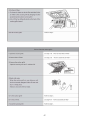
1
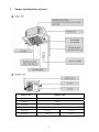
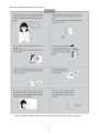
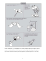
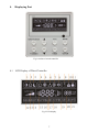
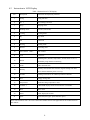
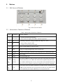
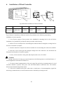
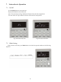
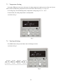
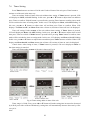
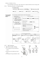
V1CI-12 V1CI-18 V1CI-24 V1CI-30 V1CI-36 V1CI-45 Cassette Type Air Conditioner (With Wire Controller) Contents 1. Names and functions of parts........................................................................ 1 2. Safety Considerations .................................................................................... 2 3. User Notice...................................................................................................... 6 4. Displaying Part............................................................................................... 7 4.1 LCD Display of Wired Controller...........................................................................7 4.2 Instruction to LCD Display.....................................................................................8 5. Buttons ............................................................................................................ 9 5.1 Silk Screen of Buttons ............................................................................................9 5.2 Instruction to Function of Buttons ..........................................................................9 6. Installation of Wired Controller ................................................................. 10 7. Instruction to Operation.............................................................................. 11 7.1 On/Off...................................................................................................................11 7.2 Mode Setting ........................................................................................................11 7.3 Temperature Setting..............................................................................................12 7.4 Fan Speed Setting .................................................................................................12 7.5 Swing Control Function........................................................................................13 7.6 Timer Setting ........................................................................................................14 7.7 Air Exchange Setting* ........................................................................................15 7.8 Sleep Setting .........................................................................................................16 7.9 Turbo Function Setting .........................................................................................17 7.10 SAVE Function Setting.......................................................................................18 7.11 E-HEATER Setting* .........................................................................................19 7.12 Blow Function Setting ........................................................................................20 7.13 Quiet Function Setting........................................................................................21 7.14 Field Functions ...................................................................................................22 7.15 Other Functions.....................................................................................................22 8. Error Display................................................................................................ 24 9. Remote control operation procedure(standard fitting) ............................ 27 10. Instructions of Unit Installation.................................................................. 37 10.1 Installation notes.................................................................................................37 10.2 Install of the cassette type indoor unit ................................................................38 10.3 Electric wiring ....................................................................................................45 10.4 Installation of panel ............................................................................................46 10.5 Install of outdoor unit .........................................................................................50 10.6 Products Electric Installation ..............................................................................60 11. Test operation ............................................................................................... 63 12. Optimum operation ..................................................................................... 65 13. Care and maintenance(It should be done by professionals)..................... 66 14. Trouble shooting........................................................................................... 70 15. Appendix....................................................................................................... 72 1. Names and functions of parts Indoor Unit Outdoor Unit V1CI-12 U1RS-12 V1CI-18 U1RS-18 V1CI-24 U1RS-24 V1CI-30 U1RS-30 V1CI-36 U1RS-36 U1RT-36 V1CI-45 U1RS-45 U1RT-45 1 2. Safety Considerations Please read this manual carefully before use and operate correctly as instructed in the manual. You are specially warned to note the two symbols below: WARNING! :A symbol indicating that improper operation might cause human death or severe injury WARNING! :A symbol indicating that improper operation might cause human property damage. This unit shall be used in offices, restaurants, residences or similar places. WARNING! Please seek an authorized repair station for installation work. Improper installation might cause water leakage, electric shock or fire. Please install at a place strong enough to support the weight of air conditioner unit. If not, the air conditioner unit might fall down and cause human injury or death. To ensure proper drainage, the drainage pipe shall be correctly installed according to installation instructions. Take proper measures for heat preservation to prevent condensing. Improper installation of pipes might cause leakage and wet the articles in the room. Do not use or store flammable, explosive, poisonous or other dangerous substances beside the air conditioner. In case of trouble (e.g. burnt smell), please immediately cut off the main power of air conditioner unit. Keep air flow to avoid shortage of oxygen in the room. Never insert your finger or any objects into air outlet and inlet grill. Never plug or unplug the power cable directly to start or stop the air-conditioning unit. Please take constant care to check if the mounting rack is damaged after long use. Never modify the air conditioner. Please contact the dealer or professional installation workers for repair or relocation of the air conditioner. The appliance shall not be installed in the laundry. Before installation, please check the power supply for compliance with the ratings on nameplate. Check the power safety as well.(Operating by professional) Before use, please check and confirm if the cables, drainage pipes and pipelines are correctly connected, hence to eliminate the risk of water leakage, refrigerant leakage, electric shock or fire. Main power must be securely earthed to ensure effective grounding of air conditioner unit and avoid the risk of electric shock. Please do not connect the earthing cable to coal gas pipe, water pipe, lightning rod or telephone line. Once started, the air conditioner shall not be stopped at least after 5 minutes or longer; otherwise Do not let the child to operate the air conditioner unit. Do not operate the air conditioner unit with wet hand. the oil return to compressor may be affected. Please disconnect the main power before cleaning the air conditioner or replacing the air filter.(Operating by professional) Please disconnect the main power if to put the air conditioner unit out of use for a long period. Please do not expose the air conditioner unit directly under corrosive environment with water or Please do not foot on or place any goods on air conditioner unit moisture. 2 After electrical installation, the air conditioner unit shall be energized for electrical leakage test.(Operating by professional) If the supply cord is damaged, it must be replaced by the manufacturer or its service agent or a similarly qualified person in order to avoid a hazard. An all-pole disconnection switch having a contact separation of at least 3mm in all poles should be connected in fixed wiring. The appliance shall be installed in accordance with national wiring regulations. The temperature of refrigerant circuit will be high, please keep the interconnection cable away from the copper tube. 3 Read the following carefully to assure safe use. NOTE: Children should be supervised to ensure that they do not play with the appliance. 4 NOTE: This appliance is not intended for use by persons (including children) with reduced physical, sensory or mental capabilities, or lack of experience and knowledge, unless they have been given supervision or instruction concerning use of the appliance by a person responsible for their safety. 5 3. User Notice ☆ Ensure unified power supply for each indoor unit. ☆ Never install wired controller in wet place or under sunlight directly. ☆ Shielding twisted pair line must be adopted as signal line or wiring (communication) of wired controller once the unit is installed in the place where there is electromagnetic interference. ☆ Make sure communication line is connected into correct port to avoid communication malfunction. ☆ Never knock, throw or frequently disassemble the wired controller. ☆ Never operate the wired controller with wet hand. 6 4. Displaying Part Fig.1 Outline of wired controller 4.1 LCD Display of Wired Controller Fig.2 LCD display 7 4.2 Instruction to LCD Display Table 1 Instruction to LCD Display No. Description Instruction to Displaying Contents 1 Swing Swing function 2 Air * Air exchange function 3 Sleep Sleeping states 4 Running mode 5 Cooling Cooling mode 6 Dry Dry mode 7 Fan Fan mode 8 Heating Heating mode 9 Defrost Defrosting state 10 Gate-control card* Gate control 11 Lock Lock state 12 Shield 13 Turbo 14 Memory 15 Twinkle Flicking when unit is on without operation of buttons 16 Save Energy-saving state 17 Temperature Ambient/setting temperature value 18 E-Heater* E-HEATER display means electric-heater is available 19 Blow Blow mark 20 Timer Timer-displayed location 21 Quiet Quiet state(two types: quiet and auto quiet) door unit (auto mode) Shielding state (buttons, temperature, on/off, mode or save is shielded by long-distance monitoring Turbo function state Memory state (Indoor unit resumes original setting state after power failure and then power recovery) Notes: The functions with * are reserved for other models and are not applicable for the models listed in this manual. 8 5. Buttons 5.1 Silk Screen of Buttons Fig.3 Silk screen of buttons 5.2 Instruction to Function of Buttons Table 2 Instruction to Function of Buttons No. Description 1 Enter/cancel 2 ▲ Function of Button ① Function selection and canceling; ② Press it for 5s to enquiry the outdoor ambient temperature. ① Running temperature setting of indoor unit, range :16~30°C ② Timer setting, range:0.5-24hr 6 ▼ 3 Fan Setting of high/middle/low/auto fan speed 4 Mode Setting of cooling/heating/fan/dry mode of indoor unit 5 Function Switchover among these functions of air/sleep/turbo/save/e-heater/blow/quite 7 Timer Timer setting 8 On/off Turn on/off indoor unit 4 Mode and 2▲ Press Mode and ▲for 5s under off state of the unit to enter/cancel key memory Memory function (If memory is set, indoor unit will resumer original setting state after function power failure and then power recovery. If not, indoor unit is defaulted to be off after power recovery. Memory function is defaulted to be off before outgoing.) 2▲ and 6▼ ③ Switchover between quiet/auto quiet Upon startup of the unit without malfunction or under off state of the unit, press Lock ▲ ▼ key at the same time for 5s in to lock state. In this case, any other buttons won’t respond the press. Repress ▲ ▼ key for 5s to quit lock state. 9 6. Installation of Wired Controller Fig.4 Sketch for Installation of Wired Controller No. 1 2 3 Socket’s base box Soleplate of Screw Description installed in the controller M4X25 wall 4 Front panel of controller 5 Screw ST2.2X6.5 Fig.4: Sketch for Installation of Wired Controller. Pay attention to the following items during installation of wired controller: 1. Cut off power supply of heavy-current wire embedded in mounting hole in the wall before installation. It is prohibited to perform the whole procedure with electricity. 2. Pull out 4-core twisted pair line in mounting hole and then make it through the rectangle hole at the back of controller’s soleplate. 3. Joint the controller’s soleplate on wall face and then fix it in mounting hole with screws M4X25. 4. Insert the 4-core twisted pair line through rectangle hole into controller’s slot and buckle the front panel and soleplate of controller together. 5. At last, fix the controller’s front panel and soleplate with screws ST2.2X6.5. Caution: During connection of wirings, pay special attention to the following items to avoid interference of electromagnetism to unit and even failure of it. 1. To ensure normal communication of the unit, signal line and wiring (communication) of wired controller should be separate from power cord and indoor/outdoor connection lines. The distance between them should be kept 20cm in min. 2. If the unit is installed at the place where there is interference of electromagnetism, signal line and wiring (communication) of wired controller must be shielded by twisted pair lines. 10 7. Instruction to Operation 7.1 On/Off Press On/Off button to turn on the unit. Repress this button to turn off the unit. Note: The state shown in Fig.5 indicates off-state of the unit after energization. The state shown in Fig.6 indicates on-state of the unit after energization. Fig.5 Off state of the unit 7.2 Fig.6 On state of the unit Mode Setting Under on-state of the unit, press Mode button to switch the operation modes as the following sequence: 11 7.3 Temperature Setting Press ▲ or ▼button to increase or decrease of setting temperature under on-state of the unit. If press either of them continuously, temperature will be increased or decreased by 1°C every 0.5s. In Cooling, Dry, Fan and Heating mode, temperature setting range is 16°C~30°C. In Auto mode, the setting temperature is un-adjustable. As shown in Fig.7. Fig 7 7.4 Fan Speed Setting Press Fan button, fan speed of indoor unit will change as below: As shown in Fig.8 Fig.8 12 7.5 Swing Control Function Under on-state of unit, press Function button till the unit enters swing control function and then press Enter/Cancel button to turn on “swing” control function. During swing function, press Function button till the unit enters swing control function and then press Enter/Cancel button to cancel swing control function. Swing control function setting is shown in Fig.9 Fig.9 13 7.6 Timer Setting Press Timer button to set timer off of the unit. Under off-state of the unit, press Timer button to settimer on of the unit in the same way. Timer on setting: Under off-state of the unit without timer setting, if Timer button is pressed, LCD will display xx. Hour, with ON blinking. In this case, press▲ or ▼ button to adjust timer on and then press Timer to confirm. If Mode button is pressed before pressing Timer button to confirm, timer mode will be switched to timer off setting mode. In this case, LCD displays xx. Hour, with OFF blinking. In this case, press▲ or ▼ button to adjust timer off and then press Timer to confirm. When LCD displays:”xx. Hour on off”; xx. Hour means time of timer on, but time of timer off won’t be displayed. Timer off setting: Under on-state of the unit without timer setting, if Timer button is pressed, LCD will display xx. Hour, with OFF blinking. In this case, press▲ or ▼ button to adjust timer on and then press Timer to confirm. If Mode button is pressed before pressing Timer button to confirm, timer mode will be switched to timer on setting mode. In this case, LCD displays xx. Hour, with ON blinking. In this case, press▲ or ▼ button to adjust timer on and then press Timer button to confirm. When LCD displays xx. Hour On Off, xx. Hour means time of timer off, but time of timer on won’t be displayed. Cancel timer: After setting of timer, if Timer button is pressed, LCD won’t display xx. Hour so that timer setting is canceled. Timer off setting under on-state of the unit is shown as Fig.10 Fig.10 Timer setting under on state of the unit Timer range: 0.5-24hr. Every press of▲ or ▼ button will make setting time increased or decreased by 0.5hr.If press either of them continuously, setting time will automatically increase/ decrease by 0.5hr every 0.5s. Note: 14 1. If both timer on and timer off are set in unit on interface, the wired controller only display time of time off. If both of them are set in unit off-state, only time of timer on is displayed. 2. Timer on in unit on-state is timed from the time of unit off and timer off in unit off-state is timed from the time of unit on. 7.7 Air Exchange Setting* Turn on air Exchange function: Under on-state of the unit, press Function button to go to the this function setting (Air mark blinks).AIR 1 displayed at the ambient temperature-displayed location (888) is defaulted (the last type of AIR will be displayed after adjustment).Press ▲ or ▼ button to adjust air type. Press Enter/Cancel button to turn on/off air function. After turning on this function, the air mark shows. There are 10 types of AIR, but only 1-2 types are for remote control. Refer to the following details: 1――The unit continuously runs for 60min, and fresh air valve runs for 6 min. 2――The unit continuously runs for 60min, and fresh air valve runs for 12 min. 3――The unit continuously runs for 60min, and fresh air valve runs for 18 min. 4――The unit continuously runs for 60min, and fresh air valve runs for 2 4 min. 5――The unit continuously runs for 60min, and fresh air valve runs for 30 min. 6――The unit continuously runs for 60min, and fresh air valve runs for 36 min. 7――The unit continuously runs for 60min, and fresh air valve runs for 42 min. 8――The unit continuously runs for 60min, and fresh air valve runs for 48 min. 9――The unit continuously runs for 60min, and fresh air valve runs for 54 min. 10――The unit continuously runs for 60min, and fresh air valve always runs. Turn off air Exchange function: During Air function, press Function button to go to the Air function. In this case, air mark is blinking, and then press Enter/cancel button to turn off this function. Air mark will subsequently disappear. Air Exchange setting is shown as in Fig.11: Fig.11 Air exchange device 15 Note: In air exchange mode, press Function button or there is not any operation within 5s after the last button operation, the system will be quit from air exchange setting and current energy-saving data won’t be memorized. 7.8 Sleep Setting Sleep on: Press Function button under on-state of the unit into sleep function and then press Enter/cancel button to turn on sleeping function. Sleep off: During sleep on-state, press Function button to go to the sleep function and then press Enter/cancel button to turn off this function. Sleep setting is shown as Fig.12: Fig.12 Sleep setting Sleep setting is clear after power failure and then power recovery. There is not sleep function in fan and auto mode. Note: In cooling and dry mode, if the unit with sleep function has run for 1 hour, the preset temperature will be increased by 1°C and 1°C in another 1 hour. After that, the unit will run at this temperature. In heating mode, if the unit with sleep function has run for 1 hour, the preset temperature will be decreased by 1°C and 1°C in another 1 hour. After that, the unit will run at this temperature. 16 7.9 Turbo Function Setting TURBO function: The unit at high fun speed can realize quick cooling or heating so that room temperature can quickly approach setting temperature. In cooling or heating mode, press Function button till the unit enters TURBO function and then press Enter/cancel button to turn on TURBO function. During TURBO function, press Function button till the unit enters TURBO function and then press Enter/cancel button to cancel TURBO function. TURBO function setting is shown in Fig.13 : Fig.13 Turbo Function Setting Note: 1. TURBO function will be turned off after power failure and then recovery. In dry, fan and auto mode, TURBO function can not be set and TURBO mark won’t be displayed. 2. TURBO function will be automatically canceled after setting of quiet function. 17 7.10 SAVE Function Setting Energy Saving Function: Energy saving can make the air conditioner runs in a smaller temperature range by setting lower limited value of setting temperature in cooling or dry mode and upper limited value in heating mode. Energy Saving Setting for Cooling Under on-state and in cooling or dry mode of the unit, press Function button into energy saving function, with SAVE blinking .Press ▲ or ▼ button to adjust lower limited value of setting temperature in cooing mode. After that press Enter/Cancel button to turn on energy saving function for cooling. Energy Saving Setting for Heating Under on state and in heating mode of the unit, press Function button into energy saving function, with SAVE blinking. Press Mode button into energy saving function for heating and then press▲ or ▼ button to adjust upper limited value of setting temperature in heating mode. After that, press Enter/Cancel button to turn on energy saving function for heating. After energy saving function is turned on, press Function button into energy saving function and press Enter/cancel to cancel this function. The energy saving setting is shown in the Fig.14. Fig.14 Energy Saving Setting Note: 1. In Auto running mode with save function on, the unit will be forcibly quit Auto running Mode and change to current operation mode, After setting of save, sleep function will be canceled. 2. In save mode, if Function button is pressed or there is not any operation within 5s after the last button operation, the system will be quit from save function setting and current data won’t be 18 memorized. 3. After power failure and then recovery, save function setting will be memorized. 4. The lower limited value in cooling mode is 16°C and the upper limited value in heating mode is 30°C. 5. After save setting, if the setting temperature is out of the range in the mode, the limited value will prevail. 7.11 E-HEATER Setting* E-HEATER: In the heating mode, E-heater is allowed to be turned on for improvement of efficiency. If heating mode is turned on by button operation, auxiliary electric heating function will be automatically turned on. Press Function button in heating mode to go to the auxiliary electric heating function, the E-HEATER blinking, and press Enter/cancel button to turn on this function. In this case, the E-HEATER will be displayed, which means E-heater is allowed to be turned on. If auxiliary electric heating function is on, press Function button to confirm or press Enter/cancel button to cancel. In this case, E-HEATER won’t be displayed, which means E-heater is prohibited to be turned on. The setting of this function is shown as Fig.15 below: Fig.15 Auxiliary Electric Heating Function Setting Note: E-HEATER can not be set in cooling, dry and fan mode, E-HEATER mark won’t be displayed. The setting is shown in Fig.15. 19 7.12 Blow Function Setting BLOW function: After the unit is turned off, water in evaporator of indoor unit will be automatically evaporated to avoid mildew. In cooling and dry mode, press Function button till the unit enters BLOW function, with BLOW blinking, and then press Enter/cancel button to turn on this function. In BLOW mode, press Function button till the unit enters BLOW function and then press Enter/cancel button to cancel this function. BLOW function setting is shown in Fig.16 Fig.16 Blow function setting Note: 1.After setting BLOW function, turn off the unit by pressing On/Off button on remote controller, indoor fan will run at low fan speed for 10 min. (BLOW shows).Meanwhile, if BLOW function is canceled indoor fan will be turned off directly. 2.There is not BLOW function in fan or heating mode. 20 7.13 Quiet Function Setting Quiet function consists of two kinds: QUIET and AUTO QUIET. Press Function button till the unit enters quiet function setting state, Quiet or Auto Quiet mark blinks. In this case, press▲ or ▼ button to switch between Quiet and Auto Quiet and then press Enter/cancel button to turn on this function. In quiet mode, press Function button till the unit enters quiet function. In this case, Quiet or Auto Quiet icon blinks and then press Enter/cancel button to cancel this function. Quiet function setting is shown in Fig.17 Fig.17 Quiet function setting Note: 1. During quiet function, fan speed is un-adjustable. 2. When turning on auto quiet function, the unit will enter quiet running state according to temperature difference between room temperature and setting temperature. In this case, fan speed is adjustable. If temperature difference between room temperature and setting temperature ≥ 4°C, fan will keep its current speed; if 2°C≤temperature difference ≤3℃; fan speed will be reduced by one grade ,but if it is at minimun. grade, it is un-adjustable.; if temperature difference ≤1°C, fan speed will be at minimun grade 3. In auto quiet mode, fan speed can not be raised but reduced. If high fan speed is manually adjusted, auto quiet mode will quit. 21 4. There is not auto quiet function in fan or dry mode. Quiet off is default after power failure and then power recovery. 5. If quite function is set, turbo function will be canceled. 7.14 Field Functions Under off-state of the unit, press Function and Timer buttons continuously for 5s to go to the debugging menu. Press Mode button to adjust the setting items and ▲ or ▼ button to set the actual value. 7.14.1 Ambient Temperature Sensor Setting In field setting mode, press Mode button to adjust the temperature displayed location displaying 00, and press ▲ or ▼ button to adjust setting state at timer displayed location. There are 3 types for selection: ⑴ Indoor ambient temperature is that at return air inlet (01 is displayed at timer displayed location) ⑵ Indoor ambient temperature is that at the place of screen (02 is displayed at timer displayed location) ⑶ Return air inlet temperature sensor shall be selected for cooling, dry and fan modes and wired controller temperature sensor (03 is displayed at timer displayed location) shall be selected for heating and auto modes. 7.14.2 Three Grades of Speed for Indoor Fan* In field setting mode, press Mode button to adjust the temperature displayed location displaying 01 and press ▲ or ▼ button to adjust setting state at timer displayed location. There are 2 types for selection: ⑴ 3 low grades (LCD displays 01) ⑵ 3 high grades (LCD displays 02) Three low grades indicate high, medium and low grades and 3 high grades indicate super-high, high and medium grades. Press Enter/Cancel button to save the setting and quit after setting. If there is not any operation within 20s after the system responds to the last button operation in this interface, the system will quit this menu and display normal off-state; meanwhile, current setting won’t be saved. 7.15 Other Functions 7.15.1 Lock Function Upon startup of the unit without malfunction or under off-state of the unit, press ▲ and ▼buttons at the same time for 5s till the wired controller enters lock state. In this case, LCD displays: . After that, repress these two buttons at the same time for 5s to quit lock state. Under lock state, any other buttons won’t give any response to the press. 7.15.2 Memory Function Memory switchover: Under off-state of the unit, press Mode and ▲ buttons at the same time for 5s to switch memory modes. During setting memory mode, Memory will be displayed. If this function is not set, the unit will be under off state after power failure and then power recovery. Memory recovery: If memory mode has been set for wired controller, the wired controller after power failure will resume its original running state upon power recovery. 22 Note: It will take about 5 seconds to save all the information, therefore, please do not cut down the power at this time, or it may fails. 7.15.3 Enquiry of Outdoor Ambient Temperature Under on or off state of the unit, press Enter/Cancel button for 5s, outdoor ambient temperature will be displayed at temperature displaying location after a sound of click. This enquiry state will quit by pressing any button. If there is not any operation for 20s, it will automatically quit. Note: 1. This function will be shielded after energization of 12hr for some models of the units without outdoor ambient sensors. Please refer to Instruction for details. 2. If malfunction of outdoor ambient sensor occurs, this function will be shielded in 12hr. 7.15.4 Selection of Centigrade and Fahrenheit Under off state of the unit, press Mode and ▼ at the same time for 5s, the displayer panel will switch between Centigrade and Fahrenheit. 7.15.5 Master/Slave Wired Controller Setting Under the off status of the unit, press “Enter/cancel” and “Mode” at the same time for 5 seconds to go to the master/slave wired controller setting interface, and then press ▲ or ▼ to make the adjustment. In this case, only in the temperature display is there numbers displayed, 01 for the master wired controller and 02 for the slave wired controller. After that, press “Enter/cancel” to save the setting and quit this interface. If there is not any operation in 20 seconds on this interface after the last button press, the system will quit automatically to the normal off status without saving the current setting. Note: If there is only one wired controller, it only can be set as the master; otherwise the unit won’t run normally. 7.15.6 Gate-control Display Function * If there is gate control system, the unit can run after plugging in card and stop after pulling out the card. If memory function is on, the unit after plugging out of card and then plugging in will run according to the memory. If the card is not plugged in (or poor plugging), the mark will show and the unit will be turned off. If memory function is off, the unit after plugging out the out will be turned off and the mark will show. If re-plugging in the card, the mark will disappear and the unit enter will enter off state. Note: 1. During long-distance monitoring, the unit on /off cannot be controlled by the card, but the mark will also show after plugging in the card. 2. The unit cannot be controlled by button operation after plugging out the card. 23 8. Error Display If there is malfunction during running of the system, LCD will display error code at temperature–displayed location. Once there is more than one malfunction, error codes will be displayed circularly. If there are multiple circuit systems, the system number of failed system will be displayed before the colon (not for single system). If malfunction occurs, turn off the unit and contact nearest dealer for help. As shown in Fig.18, it means high pressure protection of system 2 under unit on. Fig.18 Error code meaning: Error code Malfunction E0 E1 E2 Water Pump Malfunction High pressure protection of compressor E3 Indoor anti-freezing protection Low pressure protection of compressor E4 High discharge temperature protection of compressor E5 Compressor overload protection E6 Communication malfunction E9 Water overflow protection F0 Indoor unit ambient sensor malfunction at air return opening F1 Evaporator sensor malfunction F2 Condenser sensor malfunction F3 Outdoor unit ambient temperature sensor malfunction F4 Discharge temperature sensor malfunction F5 Ambient sensor malfunction on Displayer (or LED board) 24 Definition of Malfunction Codes of DC Inverter General Outdoor Unit V1.6 Malfunction Item Outdoor unit display of dual 8 Indoor Unit numeral tube Display DC busbar overvoltage protection PH E5 Overheat protection of radiator P8 E5 Current sensor malfunction Pc E5 Carbon fin sensor malfunction P7 E5 Compressor current protection P5 E5 Low voltage protection PL E5 Compressor startup failure Lc E5 PFC abnormality Hc E5 Compressor clogged LE E5 Drive resetting P0 E5 The compressor motor in loss of synchronization H7 E5 Missing phase, Speed discard Ld E5 Malfunction from driving part to main-control communication P6 E5 IPM module protection H5 E5 Compressor over speed LF E5 Sensor connection protection Pd E5 Temperature drift protection PE E5 AC contactor protection P9 E5 High-pressure protection E1 E1 Low-pressure protection E3 E3 Exhaust protection E4 E4 Compressor overload protection H3 E5 E6 E6 F3 F3 F2 F2 Communication malfunction (among indoor unit, outdoor unit and wired controller) Outdoor ambient temperature sensor malfunction Coil pipe intermediate temperature sensor malfunction of outdoor unit Exhaust temperature sensor malfunction F4 F4 08 defrost Oil return (non-malfunction) 09 no display Mismatch of indoor unit model LP no display AC current protection (input side) PA E5 Driver board environment temperature sensor malfunction PF E5 AC input voltage abnormality * PP E5 Electrification loop malfunction * PU E5 Defrosting (non-malfunction) 25 Instructions to the Error Indicating Lamps on the Panel of the Cassette Type Unit Timer Indicating Lamp (yellow) Compressor Indicating Lamp (green) Running Indicating Lamp (red) Remote Controller Receiver Instructions to the error indicating lamps on the dash receiver of the cassette type unit are described below. Once the handheld controller works, the error code will be displayed on it. Instructions to three indicating lamps on the dash receiver of the cassette type unit. Timer Indicating Lamp (yellow): it flashes when the timer is on and goes out when the timer is off. It flashes when an error about the temperature sensing bulb occurs: It flashes once when the indoor temperature sensing bulb fails. It flashes twice when the evaporator temperature sensing bulb fails It flashes three times when the condenser temperature sensing bulb fails It flashes four times when the outdoor temperature sensing bulb fails. It flashes five times when the air discharge temperature sensing bulb fails. Compressor Indicating Lamp (green): it flashes when the compressor is on and goes out when the compressor is off. It flashes when an error about the defrosting or the compressor occurs: It flashes once on the condition of the mode conflict It flashes twice on the condition of defrosting. It flashes three times on the condition of the high pressure. It flashes four times on the condition of the low pressure. It flashes five times on the condition of the overload. It flashes six times on the condition of the air discharge. Running Indicating Lamp (red): it flashes when the unit is on and goes out when the unit is off. It flashes when an error about the indoor unit occurs: It flashes once when the communication works. It flashes twice when the water overflow error occurs. It flashes three times when the anti-freezing error occurs. It flashes four times when the hi-temperature error occurs. It flashes five times when the test runs forcibly. 26 9. Remote control operation procedure(standard fitting) Name and Function-Remote Control Note: Be sure that there are no obstructions between receiver and remote controller. Don’ t drop or throw the remote controller . Don’ t let any liquid in the remote controller and put the remote controller directly under the sunlight or any place where is very hot. 27 Name and Function-Remote Control. (Remove the cover) Note: This type of remote controller is a kind of new current controller. Some buttons of the controller which are not available to this air conditioner will not be described below. Operate on unmentioned buttons would not impact on the normal use 28 COOL mode operation procedure According to difference between room temp. and set temp., microcomputer can control cooling on or not. If room temp. is higher than set temp., compressor runs at COOL mode. If room temp. is lower than set temp., compressor stops and only indoor fan motor runs. Set TEMP. should be in range of 16℃ to 30℃. 29 HEAT mode operation procedure If room temp. is lower than set temp. compressor runs at HE AT mode; If room temp. is higher than set temp., compressor and outdoor fan motor stop, only indoor fan motor runs. Set TEMP. should be in range of 16℃to 30℃ 30 DRY mode operation procedure If room Temp. is more than 2℃ below Set TEMP. , compressor and outdoor unit fan motor stop, indoor unit fan motor runs at low speed. If room Temp. is between 2℃ of Set TEMP. , the compressor and outdoor unit fan motor will run for 6 minutes and stop for 4 minutes, and always in such a cycle, the indoor unit fan motor will run at low speed. If room Temp. is more than 2℃ above Set TEMP. , compressor and outdoor unit fan motor run as COOL mode , the indoor unit fan motor runs at low speed. 31 AUTO mode operation procedure According to room temp. microcomputer can automatically set COOL.HEAT.DRY operation mode, so as far best effect. At AUTO mode operation, standard TEMP. is 26℃ for COOL mode, 24℃ for DRY mode and 20℃ for HEAT mode. 32 FAN mode operation procedure Connect the unit to power supply. Press the “ON/OFF” key. Press the mode key to select the “FAN” mode. The unit shall operate under “FAN” mode. Press the “FAN” key to select from high, medium and low speed. 33 TIMER operation procedure 34 SLEEP mode operation procedure When the unit is cooling or drying, if SLEEP operation is set, TEMP. would increase 1℃ in 1 hour and 2℃ in 2 hours. Indoor fan motor runs at low speed. When the unit is heating , if SLEEP operation is set, TEMP. would decrease 1℃ in 1 hour and 2℃ in 2 hours. Indoor fan motor runs at low speed. 35 How to inser t batteries 36 10. Instructions of Unit Installation 10.1 Installation notes 37 10.2 Install of the cassette type indoor unit Schematic diagram of installation space H >20 10.2.1 ≥ 1500 ≥1800 ≥ 1500 Unit:mm 10.2.2 Models H(mm) V1CI-12 250 V1CI-18 V1CI-24 260 V1CI-30 V1CI-36 V1CI-45 340 Select install location of the indoor unit 1. Obstruct should put away from the intake or outlet vent of the indoor unit so that the airflow can be blown though all the room. 2. Make sure that the installation had accord with the requirement of the schematic diagram of installation spaces. 3. Select the place where can stand 4 times of the weight of the indoor unit and would not increase the operating noise and oscillate. 4. The horizontally of the installation place should be guaranteed. 5. Select the place where is easy to drain out the condensate water, and connect with outdoor unit. 6. Make sure that there are enough space for care and maintenance. Make sure that the height between the indoor unit and ground is above 1800mm. 7. When installing the suspender bolt, check if the install place can stand the weight 4 times of the unit’s. If not, reinforce before installation. (Refer to the install cardboard and find where should be reinforced) Note! There will be lots of lampblack and dust stick on the acentric fan, heat exchanger and water pump 38 in dining room and kitchen, which would reduce the capacity of heat exchanger, lead water leakage and abnormal operation of the water pump. The following treatment should be taken under this circumstance: 1. Ensure that the smoke trap above cooker has enough capacity to obviate lampblack to prevent the indraft of the lampblack by the air conditioner. 2. Keep the air conditioner far from the kitchen so that the lampblack would not be indraft by the air conditioner. 10.2.3 Important notice ☆ To guarantee the good performance, the unit must be installed by professional personnel according with this instruction. ☆ contact the local INVENTOR special nominated repair department before installation. Any Please malfunction caused by the unit that is installed by the department that is not special nominated by INVENTOR would not deal with on time by the inconvenience of the business contact. Dimension of ceiling opening and location of the hoisting screw (M10) (□ 650mm)(Grille measurement) □ 25-15/32"(650mm) (Hanging bolt position) 15-3/4"(400mm) 17-5/16"(440mm) Hanging bolt position 23-27/32"(606mm) 10.2.4 V1CI-12 39 2-19/32"(66mm) 780(Gaps between hoisting screw rods) Indoor unit) 840( 890*( Ceiling opening) 950(Decorated surface boards) R efriger ant pi pe H oi sting s cr ew(X 4) 68 0( Gaps b etween ho isting sc rew rods) 840( I ndoo r uni t) 890( Ceiling openi ng) 950( D ecorated sur face bo ar ds) V1CI-18 V1CI-24 V1CI-30 V1CI-36 V1CI-45 ☆ The drilling of holes in the ceiling must be done by the professional personnel. Fig.19 Notes: The dimension for the ceiling openings with * marks can be as large as 910mm. But the overlapping sections of the ceiling and the decorated surface boards should be maintained at no less than 20mm. 40 10.2.5 Main body of hoisting air conditioner Nut (supplied at scene) Gasket (attachment) Insert Hoisting stand Tighten (double nuts) Gasket anchor board (attachment) [Fix the gasket firmly] [Fix the hoisting stand firmly] Bolt of one of the angle of outlet pipe is fix on the angle of the drainage slot Center of the ceiling opening Install cardboard Water lever Polyethylene pipe Bolt (attachment) Bolt(attachment) [Fix the install cardboard] Fig.20 1. The primary step for install the indoor unit. ☆ When attach the hoisting stand on hoisting screw, do use nut and gasket individually at the upper and lower of the hoisting stand to fix it. The use of gasket anchor board can prevent gasket break off. 2. Use install cardboard ☆ Please refer to the install cardboard about the dimension of ceiling opening. ☆ The central mark of the ceiling opening is marked on the install cardboard. ☆ Install the install cardboard on the unit by bolt (3 piece), and fix the angle of the drainage pipe at the outlet vent by bolt. 3. Adjust the unit to the suitable install place. 4. Check if the unit is horizontal. ☆ Inner drainage pump and bobber switch are included in the indoor unit, check if 4 angle of every unit are horizontal by water lever. (If the unit is slant toward the opposite of the coagulate water flow, there may be malfunction of the bobber switch and lead water drop.) 5. Backout the gasket anchor board used to prevent gasket break off and tighten the nut on it. 6. Backout the install cardboard. Note! ● Please do tighten the nuts and bolts to prevent air conditioner break off. 41 10.2.6 Connect the refrigerant pipe Selection of Connecting Pipe The refrigerant is R410A, GWP=2020 ODP=0 Table 3 refrigerant pipe selecting Size of Fitting Pipe Item Model U1RS-12 V1CI-12 U1RS-18 V1CI-18 U1RS-24 V1CI-24 U1RS-30 V1CI-30 U1RS-36 V1CI-36 U1RT-36 V1CI-36 U1RS-45 V1CI-45 U1RT-45 V1CI-45 (Inch) Gas Pipe Liquid Pipe Max Max Height Pipe Difference between Length Indoor Unit and (m) Outdoor Unit(m) Amount of Additional Refrigerant to Be Filled For Extra Length of Pipe 3/8 1/4 20 15 30g/m 1/2 1/4 20 15 30g/m 5/8 3/8 30 15 60g/m 5/8 3/8 50 30 60g/m Note: 1. The standard pipe length is 5m, When the length (L) of the connecting pipe is less than or equals 7m, there is no need to add refrigerant. If the connecting pipe is longer than 7m, it is required to add refrigerant, in the above table, the amounts of refrigerant to be added for the models are listed for each additional meter of pipe length. 2. The pipe wall thickness shall be 0.5-1.0mm and the pipe wall shall be able to withstand the pressure of 6.0MPa. 3. The longer the connecting pipe, the lower the cooling effect and the heating effect. 42 Smear freeze motoroil here Median sponge (attachment) (entwine the wiring interface with seal mat) Thread fasten(x4) Torque wrench Heat preservation sheath of liquid inlet tube (attachment) (for liquid tube) Heat preservation sheath of gas collection tube (attachment)(for gas tube) Spanner Gas collection tube Liquid inlet tube Wiring interface Fig.3 Fig.21 Flare nut ☆ When connect the pipe to the unit or backout it from the unit, please do use both spanner and torque wrench. As shown in Fig.21. ☆ When connect, smear both inside and outside of the flare nut with freeze motor oil, screw it by hand and then tighten it with spanner. ☆ Refer to Table 4 to check if the wrench had been tightened (too tight would mangle the nut and lead leakage). Table 4 the tightening torque needed for tightening nut Diameter(Inch) Surface thickness(mm) Tightening torque (N·m) φ1/4 ≥0.5 15-30 φ3/8 ≥0.71 30-40 φ1/2 ≥1 45-50 φ5/8 ≥1 60-65 φ3/4 ≥1 70-75 ☆ Examine the connection pipe to see if it had gas leakage, and then take the treatment of heat insulation, as shown in the Fig.21. ☆ Only use median sponge to entwine the wiring interface of the gas pipe and heat preservation sheath of the gas collection tube. 43 10.2.7 1. Drainage hose Install the drain hose ☆ The diameter of the drain hose should be equal or bigger than the connection pipe’s. (The diameter of polythene pipe: Outer diameter 25mm Surface thickness ≥1.5mm) ☆ Drain hose should be short and drooping gradient should at less 1/100 to prevent the formation of air bubble. ☆ If drain hose cannot has enough drooping gradient, drain raising pipe should be added. ☆ To prevent bent of the drain hose, the distance between hoisting stand should is 1 to 1.5m. 1-1.5m ○(Correct) 1/100 or more gradient × (wrong) ☆ Use the drain hose and clamp attached. Sponge(attachment) Insert the drain hose to the drain vent, and then tighten the clamp. Clamp Clamp(attachment) ☆ Entwine the big sponge on the clamp of drain hose to insulate heat. ☆ Heat insulation should be done to ● indoor drain hose. Note of drainage raising pipe Sponge (gray) Drain hose Below 4mm ☆ The install height of the drain raising pipe should less than 280mm. ☆ The drain raising pipe should form a upright angle with the unit, and distance to unit should not beyond 300mm. 2. Instruction D rain hose(attachm ent) endure the . so that the drain hole doesn’t has to unnecessary outside below500mm drain hose should be within 75mm below75mm ☆ The slant gradient of the attached force. ☆ Please install the drain hose according to the following process if several drain hoses join together. 44 T-tie in join drain hose . Above100mm The specs of the selected join drain hose should fits the running capacity of the unit. ☆ Check the smoothness of drain after installation. ☆ Check the drain state by immitting 600cc water slowly from the outlet vent or test hole. ☆ Check the drain in the state of refrigerating after installation of the electric circuit. [ W ay of immiting ] Drain hose Drain vent for repair use (plastic stopper is included) (drain the water in waterspout by this outlet vent) Test hole cover Test hole < Immiting water from the rest hole > . Above100mm Plastic water pot (The length of the pipe should be about 100mm.) < Immiting water from the outlet vent terminal> ● Warning: Before obtaining access to terminals, all supply circuits must be disconnected. 10.3 Electric wiring 1. All field supplied parts and materials must conform to local laws and regulations. 2. For electric wiring, refer to WIRING DIAGRAM attached to the unit body. 3. All wiring must be performed by a skilled technician. 4. A circuit breaker capable of shutting down power supply to the entire system and which have at least 3 mm contact separation in each pole must be install in the fixed wiring. 5. Earth properly. 6. Wiring must conform to national laws and regulations. 7. The fixed wiring must be installed with a protector with no more that 30 mA leakage current. 8. If the supply cord is damaged, it must be replaced by the manufacturer or its service agents or a similar qualified person in order to avoid a hazard. Caution: Take great care when carrying out the following connections, so as to avoid malfunction of the air-conditioning unit because of electromagnetic interference. (1) The signal line of the wire controller must be separated from the power line and the connecting line (signal wire) between the indoor unit and the outdoor unit. (2) In case the unit is installed in a place vulnerable by electromagnetic interference, it is better to use shielded cable or double-twisted cable as the signal wire. 45 10.3.1 Wiring of the indoor unit. Remove the control box lid, pull the wires inside through rubber bush and wiring according to the WIRING DIAGRAM, then tighten it with clamp. 1) Remove the control box lid; pull wires inside through rubber bush 2) Connect the power supply cable to the “L, N” terminals and the grounding screw 3) Use cable fastener to bundle and fix the cable. 4) After wiring, tighten it with clamp and fix the control box lid. ● Precautions: Be sure to connect the indoor unit and outdoor unit at right poles. 10.3.2 Connection of Signal Line of Wire Controller 1. Open the cover of the electric box of the indoor unit. 2. Pull the signal cable of the wire controller through the rubber ring. 3. Plug the signal line of the wire controller onto the 4-bit pin socket at the circuit board of the indoor unit. 4. Use cable fastener to bundle and fix the signal cable of the wire controller. 10.4 Installation of panel ●Set the panel to the indoor unit body by matching the position of the swing flap motor of the decoration panel to the piping position of the indoor unit as shown in Fig.22. ●Install the decoration panel 1. Hang the latch, which is located on the opposite side of the swing flap motor on the panel, temporarily to the hook of the indoor unit. (2 Positions) 2. Temporarily hang the remaining 2 latches to the hooks on the sides of the indoor unit.(Be careful not to let the swing motor lead wire get caught in the sealing material.) 3. Screw all 4 hexagon head screws located right beneath the latches in approximately 15mm.(Panel will rise) 4. Adjust the panel by turning it to the arrowed direction in Fig.22, so that the ceiling opening is completely covered. 5. Tighten the screws until the thickness of the sealing material between the panel and the indoor unit 46 body is reduced to 5~8 mm. Fig. 22 Precautions 1. Improper screwing of the screws may cause the troubles shown in Fig.23 Fig.23 2. If gap is still left between the ceiling and the panel after screwing the screws, readjust the height of the indoor unit body (Refer to Fig.24) Fig.24 ● After fixing, make sure there is no gap between the ceiling and panel 47 3. Wiring of the decoration panel. Connect the joints for swing flap motor lead wire (at 2 places) installed on the panel (Refer to the figure below) NOTE: Two butted terminals of the air deflector fan must be placed inside the electric box. (Refer to Fig.25) 48 Butted Terminals ButtedTermin Fig.25 49 10.5 Install of outdoor unit 10.5.1 Profile Dimensions of Outdoor Unit Model U1RS-24 U1RS-36 U1RT-36 U1RS-45 U1RT-45 U1RS-12 U1RS-18 776 320 955 396 980 427 1107 440 tem A B U1RS-30 C 540 700 790 1100 D 510 560 610 631 E 286 360 395 400 10.5.2 Schematic diagram of installation spaces 10.5.3 Precautions on Installation of Outdoor Unit To ensure the unit in proper function, selection of installation location must be in accordance with following principles: 1) Outdoor unit shall be installed so that the air discharged by outdoor unit will not return and that sufficient space for repair shall be provided around the machine. 2) The installation site must have good ventilation, so that the outdoor unit can take in and exhaust enough air. Ensure that there is no obstacle for the air intake and exhaust of the outdoor unit. If there is any obstacle blocking the air intake or exhaust, remove it. 3) Place of installation shall be strong enough to support the weight of outdoor unit, and it shall be able to insulate noise and prevent vibration. Ensure that the wind and noise from the unit will not affect your neighbors. 4) Avoid direct sunshine over the unit. It is better to set up a sun shield as the protection. 5) Place of installation must be able to drain the rainwater and defrosting water. 6) Place of installation must ensure the machine will not be buried under snow or subject to the 50 influence of rubbish or oil fog. 7) The installation site must be at a place where the air exhaust outlet does not face strong wind. 10.5.4 The three principles of refrigerant piping 10.5.5 Pipe Preparation 1. Pipe & Electrical Wire Cutting 1) Use cutting tools easily found in the market. 2) Measure precisely both outer & inter pipes. 3) The length of the pipe should be a little 51 longer than the actual measured value. 4) The wire should be 1.5m longer than the refrigerant tube. 2. Reaming 1) Clean the inside of the inner refrigerant tube. 2) While reaming, the tube end must be on the top of the reamer to prevent any dust going back into the tube. 3. Flaring the Pipe End Flare both ends of the pipe with flaring kits by fitting the flare nut on the pipe before flaring. Set the die on the pipe in the way that the pipe end is 0.5mm above the top of the die. Then, check if the pipe end is even and perfectly round or not. 4. Wire Connecting and Taping (See the figure on right) 52 10.5.6 Connecting Pipe 1. Match the flaring of copper pipe to the center of screwed connection, and then screw the flared nut up by hands. 2. Screw flaring nut with torque wrench until the spanner clatters, which is shown in the figure below. Refer to Table 5 to check if the wrench had been tightened (too tight would mangle the nut and lead leakage). Table 5 the tightening torque needed for tightening nut Diameter(Inch) Surface thickness(mm) Tightening torque (N·m) φ1/4 ≥0.5 15-30 φ3/8 ≥0.71 30-40 φ1/2 ≥1 45-50 φ5/8 ≥1 60-65 φ3/4 ≥1 70-75 3. Degree of curvature of the tubing cannot be too small or the pipe might be broken up. When bend the piping, bending apparatus shall be applied. 4. Brazing port shall be downward or horizontal when brazing the pipeline. Try to avoid the upward brazing as shown in figure below which easily affects welding quality and causes leakage. 5. Wrap connecting pipe and the joints that have not insulated with sponge and bind them up with plastic tape. 10.5.7 Air Purging The purpose of the air purging is to get rid of moisture and air in the system, otherwise moisture and air may cause ineffectiveness of the compressor which directly affects the cooling capacity. 1. Purging by Using Vacuum 1) Take out the nut cover of the inlet for refrigerant. 53 2) Connect the tube of the vacuum watch with the vacuum pump, having the low-pressure end linking to the inlet for refrigerant. As shown in figure on right. 3) Starting the vacuum pump, when the indicator turns to-1 bar, closing the low pressure handle and stopping vacuum. Keep for 15 minutes, ensuring the pressure of the vacuum watch remains. 4) Take out the valve cover of the gas valve together with the liquid valve. 5) Loosing the cord of liquid valve until the pressure rise to 0 bar. 6) Dismantle the tube from the cover of the inlet for refrigerant then, tighten the cover. 7) Loose the valve cord of the gas valve as well as the liquid valve entirely. 8) Tighten the valve cover of the gas valve and liquid valve so as to check whether leakage occurred. 2. Gap Leakage Check Check if it leaks or not by applying soapsuds on every joint and then inspect carefully. After the check, wipe them off completely. Cover the indoor unit joint with pipe insulation and four plastic bands to prevent condensing at joints. 10.5.8 Liquid Pipe and Drain Pipe If the outdoor unit is installed lower than the indoor unit (See Fig.26) 1) A drain pipe should be above ground and the end of the pipe does not dip into water. All pipes must be restrained to the wall by saddles. 2) Taping pipes must be done from bottom to top. 3) All pipes are bound together by tape and restrained to wall by saddles. Fig.26 If the outdoor unit is installed higher than the indoor unit (See Fig.27) 1) Taping should be done from lower to the upper part. 2) All pipes are bound and taped together and also should be trapped to prevent water from returning to the room (See Fig.27) 3) Restraint all pipes to the wall with saddles. 54 Fig.27 10.5.9 Installation of Protective Layer of Connecting Pipe 1. To avoid generation of condensate on the connecting pipe and avoid leakage, the big pipe and the small pipe of the connecting pipe must be covered by thermal insulation materials, be bundled by adhesive tape, and be isolated from air. 2. The joint connecting to the indoor unit must be wrapped by thermal insulation material. There shall be no gap between the connecting pipe joint and the wall of the indoor unit. Refer to the figure on right. Caution: F 1) After the pipes are wrapped by protective materials, never bend the pipes to form very small angle, and otherwise the pipes may crack or break. 2) Do not wrap the protective tape too tight, and otherwise the efficiency of thermal insulation may be decreased. Ensure that the condensate drainage flexible tube is separate from the bundled pipes. 3) After the protective work is completed and the pipes are wrapped, use seal material to block the hole in the wall, so as to prevent rain and wind from entering the room. 55 3. Use adhesive tape to wrap the pipes: 1) Use adhesive tape to bundle the connecting pipe and the cables together. To prevent condensate from overflowing out from the drainage pipe, separate the drainage pipe firm the connecting pipe and the cables. 2) Use thermal insulation tape to wrap the pipes from the bottom of the outdoor unit until the upper end of the pipe where the pipe enters the wall. When wrapping thermal insulation tape, the later circle of tape must cover half of the front circle of tape Refer to the figure on right. 3) Wrapped pipe must be fixed to wall using pipe clamps. 10.5.10 Cautions in Connecting Pipes The layout of connecting pipeline shall comply with the following principles according to actual situation. 1. The length of connecting pipe shall be short as much as possible and it is better to restrain the length within 5m. 2. Shorten the height difference between indoor and outdoor unit as much as possible. 3. Reduce the height difference between indoor and outdoor units as it might be. 4. Lessen the quantity of elbows as much as possible. 5. When the length of connecting pipe exceeds 20m, check if the lubricant of the system is enough. If not, add some in the oil trap properly. 6. Refrigerants volume inside the outdoor unit suit for connecting pipe with 7m. If connecting pipe shall be prolonged, refrigerants shall be added accordingly. Every 1m prolonged, the added volume of refrigerant can refer to Table 3. The allowable max length of pipe can be also found in the table. 56 7. When installing the unit, if difference in height between indoor and outdoor unit exceeds 10m, one oil loop is required every 6m. Please refer to Fig.29for layout of pipeline. Liquid pipe (thin pipe) - - - - - - Gas pipe (heavy pipe) Fig.29 10.5.11 Position and Method of Installing Wire Controller 1. One end of the control wire of the wired remote controller is connected to main board in the electric box of indoor unit; it should be tightened by wire clamps, while the other end should be connected to the wired controller. The special control wire be used between the indoor unit and wired remote controller, of which the length is 8 meters. 2. The material to be adopted for the control wire should be metallic substance. The wired controller could not be disassembled and the control wire to be used for the wired controller should not be changed by users optionally. The installation and maintenance should be carried out by the installer. 3. Firstly select an installation position. According to the size of the control wire for the wired remote controller, leave a recess or an embedded wire hole to bury the communication line. 4. If the control wire between the wired remote controller and the indoor unit is surface-mounted, use 1# metallic pipe and make matching recess in the wall (refer to Fig. 30); If concealed installation is adopted, 1# metallic pipe can be used (Refer to Fig. 31). 5. No matter if surface mounting or concealed mounting is selected, it is required to drill 2 holes (in the same level) between which the distance shall be the same as the distance (60mm) of installation holes in the bottom plate of the wired controller. Then insert a wood plug into each hole, fix the bottom plate of the wire controller to the way through these two holes, plug the control wire onto the control panel, and lastly install the panel of the wire controller.( Refer to Fig. 4) 57 Fig.30 Fig.31 Caution: During the installation of the bottom plate of the wired controller, pay attention to the direction of the bottom plate. The plate’s side with two notches must be at the lower position, otherwise the panel of the wired controller cannot be correctly installed. Caution: 1. The communication distance between the main board and the wired controller can be as far as 20m (The standard distance is 8m). 2. The wired controller shall not be installed in a place where there is water drop or large amount of water vapor. 58 10.5.12 Power Cable Connection Caution: Before installing the electrical equipment, please pay attention to the following matters which have been specially pointed out by our designers: 1) Check that if the power supply used conforms to the rated power supply specified on the nameplate. 2) The capacity of the power supply must be large enough. The section area of fitting line in the room shall be larger than that of Table 6 shows. 3) The lines must be installed by professional personnel. An electricity leakage protection switch and an air switch with gap between electrode heads larger than 3 mm shall be installed in the fixed line. 2 Connection of single wire 1) Use wire stripper to strip the insulation layer (25mm long) from the end of the single wire. 2) Remove the screw at the terminal board of the air-conditioning unit. 3) User pliers to bend the end of the single wire so that a loop matching the screw size is formed. 4) Put the screw through the loop of the single wire and fix the loop at the terminal board. 3. Connection of multiple twisted wires 1) Use wire stripper to strip the insulation layer (10mm long) from the end of the multiple twisted wires. 2) Remove the screw at the terminal board of the air-conditioning unit. 3) Use crimping pliers to connect a terminal (matching the size of the screw) at the end of the multiple twisted wires. 4) Put the screw through the terminal of the multiple twisted wires and fix the terminal at the terminal board. Warning: 1) If the power supply flexible line or the signal line of the equipment is damaged, only use special flexible line to replace it. 2) Before connecting lines, read the voltages of the relevant parts on the nameplate. Then carry out line connection according to the schematic diagram. 59 3) The air-conditioning unit shall have special power supply line which shall be equipped with electricity leakage switch and air switch, so as to deal with overload conditions. 4) The air-conditioning unit must have grounding to avoid hazard owing to insulation failure. 5) All fitting lines must use crimp terminals or single wire. If multiple twisted wires are connected to terminal board, arc may arise. 6) All line connections must conform to the schematic diagram of lines. Wrong connection may cause abnormal operation or damage of the air-conditioning unit. 7) Do not let any cable contact the refrigerant pipe, the compressor and moving parts such as fan. 8) Do not change the internal line connections inside the air-conditioning unit. The manufacturer shall not be liable for any loss or abnormal operation arising from wrong line connections. 10.5.13 Connection of the Power Cable Caution: 1. Air-conditioning unit with single-phase power supply 1) Remove the front-side panel of the outdoor unit. Take great care when carrying 2) Pass the cable though rubber ring. out the following connections, so 3) Connect the power supply cable to the “L, N” as to avoid malfunction of the air-conditioning unit because of terminals and the grounding screw. 4) Use cable fastener to bundle and fix the cable. 2. Air-conditioning unit with 3-phase power supply electromagnetic interference: In case the unit is installed in a place vulnerable by 1) Remove the front-side panel of the outdoor unit. electromagnetic interference, it 2) Attach rubber ring to the cable-cross hole of the is better to use shielded cable or outdoor unit. double-twisted cable as the signal wire. 3) Pass the cable though rubber ring. 4) Connect the power cable to the terminal and earthing screws marked “L1, L2, L3 & N”. 5) Use cable fastener to bundle and fix the cable. 10.6 Products Electric Installation Caution! The unit should be reliably earthed, if it is improperly earthed that may cause electric shock or fire. Wiring layout ☆ Installation should be conducted by National Wiring Regulation. ☆ The rated voltage and exclusive power supply must be adopted for the air conditioners. ☆ The power cable should be reliable and fixed, in order to avoid the wiring terminal be suffered from force. And do not drag the power cable forcibly. ☆ The wire diameter of power cable should be large enough, if power cable and connection wire ☆ All electric installation must be done by professional personnel according to local law, be damaged, it should be replaced by the exclusive cable. 60 regulation and this manual. ☆ It should be reliably earthed, and it should be connected to the special earth device, the installation work should be operated by the professional. ☆ The creepage protecting switch and air switch must be installed. ☆ Air switch should have the thermal dropout and magnetic dropout function, in order to avoid ☆ The on spot connection should refer to the circuit diagram, which is stuck on the unit body. the short circuit and overload. Table 6 The model selection recommend table for air switch and power cable Capability of Air Switch Minimum Sectional Area of Earth Wire (A) (mm2) Minimum Sectional Area of Power Supply Wire (mm2) U1RS-12 / V1CI-12 16/6.0 2.5/1.0 2.5/1.0 U1RS-18 / V1CI-18 20/6.0 4.0/1.0 4.0/1.0 U1RS-24/ V1CI-24 20/10 4.0/1.5 4.0/1.5 32/10 6.0/1.5 6.0/1.5 U1RS-36/ V1CI-36 32/10 6.0/1.5 6.0/1.5 U1RS-45/ V1CI-45 32/10 6.0/1.5 6.0/1.5 U1RT-36 / V1CI-36 25/10 6.0/1.5 6.0/1.5 25/10 6.0/1.5 6.0/1.5 Model U1RS-30/ V1CI-30 U1RT-45 / V1CI-45 Power Supply (V, Ph, Hz) 220-240, ~,50 380-415, 3N~,50 1. The power cable used in the unit is copper cable; the working temperature should not exceed the specified value. 2. If the power cable is longer than 15 meters, please enlarge the cross section of power cable adequately, in order to avoid the accident due to overload. ● Requirement for ground ☆ Air conditioner is the I class electric appliance, thus please do conduct reliable grounding measure. ☆ The yellow-green two-color wiring of air conditioner is grounding wire and cannot be used for other purposes. It cannot be cut off and be fixed by screw, otherwise it would cause electric shock. ☆ The user must offer the reliable grounding terminal. Please don’t connect the grounding wire to the following places: ① Water pipe; ② Gas pipe; ③ Blowing pipe; ④ Other places that professional personnel consider them unreliable. The power cable, communication wire connection between indoor and outdoor The section area of cables selected by users must not be smaller than the specifications show diagram. The signal wire between indoor and outdoor unit shall be installed in the shielded bushing。 Schematic Diagram of Unit Line Connection: 61 U1RS-12 + U1RS-18 + U1RS-24 + U1RS-30 U1RS-36 U1RS-45 + + + ①Power cord 3x2.5mm2 (H07RN-F) ③Communication Cords ①Power cord 3x4.0mm2 (H07RN-F) ③Communication Cords ①Power cord 3x4.0mm2 (H07RN-F) ③Communication Cords ①Power cord 3x6.0mm2 (H07RN-F) ③Communication Cords V1CI-12 ②Power cord 3x1.0mm2 (H05V V-F) V1CI-18 ②Power cord 3x1.0mm2 (H05V V-F) V1CI-24 ②Power cord 3x1.5mm2 (H05V V-F) ②Power cord 3x1.5mm2 (H05V V-F) + + U1RT-36 U1RT-45 2 ①Power cord 5x 6.0mm (H07RN-F) ③Communication Cords 62 V1CI-30 V1CI-36 V1CI-45 V1CI-36 V1CI-45 ②Power cord 3x1.5mm2 (H05V V-F) Test operation 11.1 Prepare for test (1) Do not turn on the power switch before all installation is finished. (2) Connect wires correctly and firmly. (3) Open the check valve. (4) Remove all dust. 11.2 Testing (1) Turn on the power switch and press ON/OFF button. (2) Press MODE button select COOL, HEAT, FAN, etc to test whether it operates normally. 11.3 Emergency operation. When the batteries fail or when the remote controller is missing, operate as shown below. * On stopping you can press the AUTO button on cover NO.Ⅱ, until it is in AUTO mode. The cover NO.Ⅱis the part of the panel. As the picture below. The air conditioner select from COOL, HEAT, DRY, FAN modes automatically. * On operating, press the AUTO button, the air conditioner will stop. Note: The “TEST” button on the cover No. Ⅱ is specially for testing the air conditioner. When pressing it, the air conditioner will be forced to operate or stop. Do not press it when air conditioner is in normal operation. . 63 For the following items, take special care during construction and check after installation is finished Items to check If not properly done, what is likely to happen Is the indoor unit fixed firmly? The unit may drop, vibrate or make noise. Is the gas leakage test finished? It may result in insufficient cooling. Is the unit fully insulated? Condensate water may drip. Does drainage flow smoothly? Condensate water may drip. Does the power supply voltage correspond The unit may malfunction or the components to that shown on the nameplate? burn out. The unit may malfunction or the components Are wiring and piping correct? burn out. Is the unit safely grounded? Risk of electric leakage. The unit may malfunction or the components Is wiring size according to specifications? burn out. Is something blocking the air outlet or It may result in insufficient cooling. intake of either the indoor or outdoor unit? Have records of refrigerant piping length Volume of refrigerant change in the system is not and additional refrigerant change been clear. made? Note to the installer: Be sure to instruct the customer how to operate the system and show him/her the attached operation manual. Be sure the electric supply that user applies is beyond the bounds of tolerances (+/-10%, +/-1Hz). The ambient temperature should be at 5-40°C, and the humidity is 30%-95%. Transport/storage temperature should be at -25-55°C and for short period not exceeding 24h at up to +70°C. The installation altitude is beyond the height of 1000m. 64 11. Optimum operation 65 12. Care and maintenance(It should be done by professionals) Please pull out the power plug after you used the air conditioner. 66 67 68 The operation in detach and fix the flap is not including the 12K type. 69 13. Trouble shooting ★ Warning ● In case of something abnormal (such as bad smell), shut of the power switch immediately and contact service center. ● Do not repair the air conditioner by yourself because wrong repair may cause fire, please contact service center to do it for you. ★Check item shown below before contacting service center. symptom cause Corrective measures Phase opposition or fuse broken Change phase or replace fuse Power off It will restart when power is on The system does not Loose plug Put the plug into place operate at all Batteries of remote controlling fall Replace batteries Out of the remote controlling range Keep the distance in 10mm The system stops right Object at the air intake and air Remove them after it is started outlet of the air conditioner Object at the air intake and air Remove them outlet of the air conditioner Wrong temperature setting Refer to Page 12 Low fan speed Refer to Page 12 Cooling and heating is Air direction is not correct Refer to Page 13 malfunctioning Doors or windows are open Close them Direct sunshine Close the curtain or blinder Too many people in the room Too many heating sources Dirty air filter Clean it ★ Note: If trouble still exists after checking the above items, please contact service center. If your air-conditioning unit suffers from abnormal operation or failure, please first check the following points before repair: Failure Possible Reasons 1. The power supply is not connected. 2. Electrical leakage of air-conditioning unit causes tripping of leakage switch. The unit cannot be started. 3. The voltage of electrical line is too low. 4. The operating keys are locked. 5. The control loop has failure. 1. There is obstacle in front of the condenser. The unit operates for a while 2. The control loop is abnormal. and then stops. 3. Cooling operation is selected when the outdoor ambient temperature is above 52℃. 1. The air filter is dirty or blocked. 2. There is heat source or too many people inside the room. 3. The door or window is open. 4. There is obstacle at the air intake or outlet. Poor cooling effect. 5. The set temperature is too high thus cooling is hindered. 6. There is refrigerant leakage. 7. The performance of room temperature sensor becomes worse 1. The air filter is dirty or blocked. 2. The door or window is not firmly closed. 3. The set room temperature is too low thus heating is Poor heating effect hindered. 4. There is refrigerant leakage. 5. The outdoor ambient temperature is lower than -7℃. 6. Control line is abnormal. 70 continued Failure The indoor fan does not start under the heating mode. 1. 2. 3. 4. Possible Reasons The installation site of the tube sensor is not proper. Tube sensor is not correctly plugged. The connecting line of the tube sensor is broken. The capacitance has leakage. Note: 1、After carrying out the check of the above items and taking relevant measures to solve the problems found but the air-conditioning unit still does not function well, please stop the operation of the unit immediately and contact the local service agency .Only ask professional serviceman to check and repair the unit. ★ The following are not troubles 71 14. Appendix Air conditioner nominal working condition and working range: Test condition Indoor side Outdoor side DB(℃) WB(℃) DB(℃) WB(℃) Nominal cooling 27 19 35 24 Nominal heating 20 -- 7 6 Rated cooling 32 23 48 -- Low temp cooling 21 15 18 -- Rated heating 27 -- 24 18 Low temp heating 20 -- -7 -8 Note: 1. The design of this unit conforms to the requirements of EN14511 standard. 2. The air volume is measured at the relevant standard external static pressure. 3. Cooling (heating) capacity stated above is measured under nominal working conditions corresponding to standard external static pressure. The parameters are subject to change with the improvement of products, in which case the values on nameplate shall prevail. WARNING! z This appliance is not intended for use by persons (including children) with reduced physical sensory or capabilities, or leak of experience and knowledge, unless they have been given supervision on instruction concerning use of appliance by a person responsible for their safety. z Children should be supervised to ensure that they do not play with the appliance. This product must not be disposed together with the domestic waste. This product has to be disposed at an authorized place for recycling of electrical and electronic appliances. 72 66129907236