1
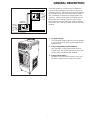
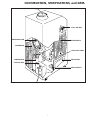
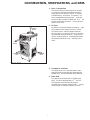
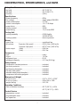
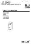
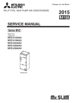
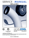
SERVICE MANUAL OFFICE PRO 24 DENSO SALES CALIFORNIA, INC. REGISTERED TO ISO 9002 FILE NO. A5537 © 2000 DENSO SALES CALIFORNIA, INC. All rights reserved. This book may not be reproduced or copied, in whole or in part, without the written permission of the publisher. DENSO SALES CALIFORNIA, INC. reserves the right to make changes without prior notice. MovinCool is a registerd trademark of DENSO Corporation. SERVICE MANUAL OFFICE PRO 24 FOREWORD This manual has been published to service the MovinCool Office Pro 24. Please use this service manual only when servicing the Office Pro 24. DEFINITION OF TERMS WARNING: Describes precautions that should be observed in order to prevent injury to the user during installation or unit operation. CAUTION: Describes precautions that should be observed in order to prevent damage to the unit or its components, which may occur during installation or unit operation if sufficient care is not taken. NOTE: Provides additional information that facilitates installation or unit operation. GENERAL PRECAUTIONS WARNINGS: • All electrical work if necessary, should only be performed by qualified electrical personnel. Repair to electrical components by non-certified technicians may result in personal injury and/or damage to the unit. All electrical components replaced must be genuine MovinCool, purchased from an authorized reseller. • When handling refrigerant, always wear proper eye protection and do not allow the refrigerant to come in contact with your skin. • Do not expose refrigerant to an open flame. • The proper electrical outlet for MovinCool units must be equipped with a “UL” approved ground-fault breaker to prevent electrical shock from the unit. • When brazing any tubing, always wear eye protection and work only in a well ventilated area. i ii TABLE OF CONTENTS FOREWORD ............................................................................................................................... i DEFINITION OF TERMS ............................................................................................................ i GENERAL PRECAUTIONS ........................................................................................................ i TABLE OF CONTENTS .............................................................................................................iii GENERAL DESCRIPTION ........................................................................................................ 1 CONSTRUCTION, SPECIFICATIONS, & DATA ....................................................................... 3 REFRIGERANT SYSTEM .......................................................................................................... 9 ELECTRICAL SYSTEM ........................................................................................................... 13 TROUBLESHOOTING & REPAIR ........................................................................................... 19 iii iv GENERAL DESCRIPTION CONDENSER (OUTDOOR UNIT) Generally speaking, conventional air conditioners cool the entire enclosed environment. They act as “heat exchangers”, requiring an interior unit (evaporator) to blow cool air into the interior and an exterior unit (condenser) to exhaust exchanged heat to the outdoors. Unlike conventional air conditioners, the MovinCool Spot Cooling System is a spot cooler which directs cool air to particular areas or objects. MovinCool Spot Cooling Systems have the following features: EVAPORATOR (INDOOR UNIT) Conventional Air Conditioner 1. Compact Design The innovative design of MovinCool has resulted in one compact unit, replacing the need for two separate units. 2. Easy Transportation and Installation With the whole cooling system built into one compact unit, MovinCool requires no piping and can be easily transported and installed. 3. Energy Conservation MovinCool is economical because it cools only the area or objects which need to be cooled. Office Pro 24 1 GENERAL DESCRIPTION 2 CONSTRUCTION, SPECIFICATIONS, and DATA EXHAUST AIR DUCT COOL AIR VENT CENTRIFUGAL FAN EVAPORATOR CONDENSER CAPILLARY TUBES DRAIN TANK COMPRESSOR CONTROL BOX DRAIN SWITCH Figure 2-1: Construction of Office Pro 24 3 CONSTRUCTION, SPECIFICATIONS, and DATA EVAPORATOR FAN CONTROL PANEL TOP PANEL EXHAUST AIR VENT RIGHT HANDLE COOL AIR VENT SIDE PANEL FAN MOTOR FRONT PANEL CONDENSER FAN CAPILLARY TUBE EVAPORATOR COMPRESSOR ACCUMULATOR DRAIN TANK CONDENSER CASTER POWER CORD Figure 2-2: Construction Diagram 4 CONSTRUCTION, SPECIFICATIONS, and DATA 1. Basic Construction The MovinCool Spot Cooling System is compact in construction because the condenser and the evaporator ar e enclosed in one unit. The interior is divided into thr ee sections. The upper fr ont face is equipped with the evaporator , while the lower fr ont face contains the drain tank. The r ear section contains the condenser , the compr essor and the contr ol box. 2. Air Flow Air drawn fr om the right side face passes thr ough the condenser which extracts the heat. This hot air is blown out thr ough the upper exhaust air duct. Air taken in fr om the fr ont face is cooled by the evaporator and then blown thr ough the cool air vent. All the air inlets ar e equipped with filters, while the exhaust air duct is pr otected by wir e mesh. EXHAUST AIR OUT COOL AIR OUT EVAPORATOR AIR IN CONDENSER AIR IN Figure 2-3: Air Flow 3. Compressor and Fans The compr essor is her metically sealed. A twospeed fan motor is used with two centrifugal fans to draw air acr oss the evaporator and condenser . 4. Drain Tank The capacity of the drain tank is 5.0 gallons (19 liters). The unit is equipped with a “T ank Full” LED and a device to automatically stop the operation of the unit when the drain tank r eaches a level of appr oximately 4.0 gallons (15 liters). 5 CONSTRUCTION, SPECIFICATIONS, and DATA Rating Conditions dry bulb ......................................................................95º F (35º C) wet bulb .....................................................................83º F (28.2º C) humidity .....................................................................(60%) Specifications power frequency ........................................................ 60Hz line voltage ................................................................single phase 208/230V power consumption ...................................................2.7 Kw current consumption .................................................. 13.1/11.8 Amps power factor ...............................................................99% starting current .......................................................... 32.9A power wiring ..............................................................12 (3-core) AWG Cooling Unit cooling capability ....................................................... 6,000 Kcal/hr 24,000 BTU/hr cooling system ...........................................................direct expansion Blower type of fan ..................................................................centrifugal fan air volume: Evaporator (High speed) ....................... 632 ft 3/min (1068 m3/h) Condenser (High speed) ........................ 867 ft 3/min (1465 m3/h) motor output (High) ........................................... 0.48 Kw (Low) ............................................0.41 Kw Compressor type ............................................................................rotary output ........................................................................1.4 Kw refrigerant type .......................................................... R-22 refrigerant capacity ....................................................2.17 lbs (0.96 kg) Safety Devices compressor overload protector .................................. included fan motor protector ....................................................included anti-freezing thermistor .............................................. included full drain tank switch .................................................. included automatic restart (power interruption) .................................. included compressor time delay program ................................ included Dimensions & Weight W x D x H (in) ............................................................21.2" x 27.4" x 47.25" W x D x H (mm) .........................................................538 x 696 x 1200 weight (lbs/kg) ...........................................................210 / 95 Operating Conditions inlet air (relative humidity) ......................................... 95º F (35º C), ≤ 60% 65º F (18.3º C), ≥ 50% Control Devices temperature control ...................................................included programmable timer .................................................. included two speed fan ............................................................included Specifications Specifications are subject to change without notice. 6 2.40 21.20 CONSTRUCTION, SPECIFICATIONS, and DATA 18.50 3.80 11.30 43.90 7.50 ø11.575 12.40 4.60 16.50 20.67 27.40 19.30 Figure 2-4: Exterior Dimensions (units: inches) 7 2.20 DATA @ 115V @ 115V 3.6 (14.3) 14 (25.2) Temperature ˚C (˚F) Cooling Capability (x103 kcal/h (BTU/h)) 3.2 (12.7) 2.8 (11.1) 12 (21.6) 10 (18.0) 8 (14.4) 2.4 (9.5) 6 (10.8) 40 50 60 70 Relative Humidity of Inlet Air (%) 2.0 (7.9) Cool Air Temperature Difference Curve 30 (86) 25 (77) @ 115V 1.6 20 (68) 10 (50) 15 (59) 20 (68) 1.4 25 (77) Power Consumption (kW) 15 (59) Wet Bulb Temperature ˚C (˚F) Cooling Capability Curve 1.2 1.0 0.8 35 (95) Dry Bulb Temperature ˚C (˚F) Dry Bulb Temperature ˚C (˚F) 35 (95) 30 (86) 25 (77) 20 (68) 15 (59) 15 (59) 20 (68) 25 (77) Wet Bulb Temperature ˚C (˚F) 8 Power Consumption Curve 30 (86) REFRIGERANT SYSTEM 1. The component par ts of the refrigerant system include the following: • Compr essor • Evaporator • Condenser • Accumulator • Capillary tube These par ts ar e all connected by copper tubing. All the connections have been brazed. EVAPORATOR CONDENSER CAPILLARY TUBE ACCUMULATOR COMPRESSOR REFRIGERANT FLOW CONDENSER ACCUMULATOR CAPILLARY TUBES FAN MOTOR EVAPORATOR Figure 3-1: Refrigerant System 9 COMPRESSOR REFRIGERANT SYSTEM 2. Compressor The compr essor used for the unit is her metically sealed. The compr essor and the compr essor motor ar e in one casing. A. Compr essor Constr uction The constr uction of a r otar y type compr essor is divided into two mechanisms. The drive mechanism (compr essor motor) and the compr ession mechanism (compr essor). When the r otor shaft of the motor (drive mechanism) tur ns, the r oller of the compr essor (compr ession mechanism) r otates to compr ess the r efrigerant. B. Basic Compr essor Operation DISCHARGE HOLE The r oller (compr ession mechanism) is set eccentrically with a certain distance given from the axis of the center of the cylinder . A spring loaded blade is mounted on the cylinder . The r oller tur ns to compr ess the refrigerant in the space between the cylinder and eccentrically mounted r oller. DISCHARGE VALVE SPRING SUCTION HOLE BLADE SHAFT The blade is in contact with the r oller by means of spring for ce. It par titions the space between the suction side and the dischar ge side to keep compr essed r efrigerant fr om retur ning to the suction side. ROLLER Figure 3-2: Compressor Operation Ther e is no suction valve. The dischar ge valve is designed not to open until the pressur e of the r efrigerant within the cylinder reaches or exceeds that of the r efrigerant on the dischar ge side. This design pr events the backwar d flow of dischar ge gas. 3. Condenser The condenser is a heat exchanger with copper tubes that ar e cover ed with thin aluminum projections called spine fins. Heat is given of f and absorbed by air being pulled acr oss the condenser fins by the centrifugal fan and then expelled thr ough the exhaust air duct. 10 CYLINDER REFRIGERANT SYSTEM 4. Capillary Tubes The capillar y tubes ar e a long thin tubes utilizing line flow r esistance to ser ve as an expansion valve. The length and the inner diameter of the capillar y tubes ar e deter mined by the capacity of the r efrigeration system, specified operating conditions, and the amount of r efrigerant. High Temp. / High Press. Liquid Refrigerant The capillar y tubes cause the high pr essur e, high temperatur e liquid r efrigerant sent fr om the condenser to expand rapidly as the r efrigerant is sprayed out thr ough the fixed orifice in the capillar y tubes. As a r esult, the temperatur e and state of the r efrigerant become low and mist-like respecitively , causing it to evaporate easily . Low Temp. / Low Press. Gas and Liquid Mixture Figure 3-3: Capillary Tube 5. Evaporator The evaporator , like the condenser , is a heat exchanger utilizing plate fins. Heat is r emoved from the air being pulled acr oss the evaporator by the centrifugal fan and the r esulting cool air is expelled thr ough the cool air vent. 6. Accumulator The accumulator is mounted on the suction gas piping between the evaporator and the compr essor. The accumulator separates the liquid r efriger ant fr om the gas r efrigerant letting only the gas refrigerant enter the compr essor. In the accumulator , suction gas is led into a vessel having a cylindrical body , and the gas speed is decr eased inside the vessel. This separates the r efrigerant contained in the gas by the for ce of gravity causing it to accumulate at the bottom of the vessel. This pr otects the compr essor fr om possible damage caused by the intake of liquid refrigerant. From Evaporator To Compressor Figure 3-4: Accumulator 11 REFRIGERANT SYSTEM EVAPORATOR INLET PIPE CONDENSER OUTLET PIPE EVAPORATOR OUTLET PIPE ASSY COMPRESSOR SUCTION PIPE (Insulated) COMPRESSOR DISCHARGE PIPE CAPILLARY TUBE CONDENSER INLET PIPE HIGH PRESSURE SWITCH PIPE (Condenser to Capillary Tube) CONNECTING PIPE (Evaporator to Compressor) Figure 3-5: Refrigerant System Piping 12 ELECTRICAL SYSTEM AP RTH THS DS 3 G T R HPRS 1 CC 1 2 2 TB MC IOLC G G CF 1 2 L0 MF HI J4 IOLF J101 J102 J103 J104 J8 (AUX1) J5 G J6 J9 J201 J2 J1 J3 AP TB CB RB MF MC CF CC RB Attachment Plug Terminal Block Control Board Relay Board Fan Motor Compressor Motor Capacitor for Fan Capacitor for Compressor IOLC IOLF HPRS DS THS RTH G J8 (AUX1) CB Internal Overload Protector of Compressor Internal Overload Protector of Fan Motor High Pressure Switch Full Drain Warning Switch Freeze Protection Thermistor Room Thermistor Ground Auxiliary Connector (CPK-5) Relay Board Relay Board Fuse DIP Switch Terminal Block Compressor Capacitor Fan Motor Capacitor Figure 4-1: Electrical System and Control Box 13 ELECTRICAL SYSTEM 1. Basic Operation of Of fice Pro 24 Electrical Cir cuit Ther e ar e two basic components used to contr ol the operation of the Classic Plus 26 Electrical System: • Contr ol Panel Assembly • Contr ol Box The Contr ol Panel Assembly contains the Contr ol Panel, Contr ol Boar d (with inputs for the fr eeze and room temperatur e ther mistors), drain switch, and a micr oprocessor . A. Fan “Only” Mode Low Fan Mode - When the “Low” Fan Mode button on the contr ol panel is pr essed, the micr oprocessor tur ns on the button’ s LED and activates the Fan “On” Relay (Relay Boar d), sending line voltage (208/ 230 VAC) to the N.C. (Nor mally Closed) contacts of the fan “mode” r elay. This output is connected to the J5 ter minal (r elay boar d) wher e the LOW SPEED wir e of the fan motor is connected. High Fan Mode – When the “High” Fan Mode button on the contr ol panel is pr essed, the micr oprocessor tur ns on the button’ s LED and activates both the Fan “On” Relay and Fan “Mode” Relay . This sends line voltage (208/230 V AC) fr om the Fan “On” Relay to the N.O. (Nor mally Open) contacts of the Fan “Mode” Relay . This output is connected to the J6 ter minal (Relay Boar d) wher e the HIGH SPEED wir e of the Fan Motor is connected. B. Cool Mode - In Addition to Fan “Only” Mode (as described above) When the Cool On/Of f button on the contr ol panel is pr essed, the micr oprocessor tur ns on the button’ s LED and if the T emperatur e Set Point is less than the cur rent r oom temperatur e, activates the Compr essor Relay (Relay Boar d). This sends line voltage (208/230 V AC) to the J4 ter minal (Relay Boar d) wher e the wir e from the Compr essor wir e har ness is connected. 14 ELECTRICAL SYSTEM 2. Control Box A. Capacitors The capacitors ar e used to temporarily boost the power output available to the fan motor and the compr essor at star t-up. Relay Board The specifications of each capacitor ar listed below: Relay Board Fuse DIP Switch Terminal Block e CAPACITOR APPLICA TION VOLTAGE RATING CAPACITANCE (µf) Fan Motor Compr essor 440 440 12.5 50 B. Relay Boar d The Relay Boar d receives signals and outputs from the contr ol boar d that contains a micr oprocessor . The r elay boar d contains the compr essor, fan on and fan mode (speed) relays. It also contains a step-down transformer that converts the line voltage (230 VAC) to 16 volts. This is then conver ted fr om AC to DC and used for r elay coil activation. The 16V (DC) power is sent to the Contr ol Panel Assembly wher e it is fur ther r educed to 5 volts for the system logic. Compressor Capacitor Fan Motor Capacitor Figure 4-2: Control Box NOTE: The relay board must be serviced as a complete assembly. It has only one serviceable component, the fuse. ! The r elay boar d also contains the DIP-Switch. The DIP-Switch is used to change the Fan Mode operation fr om Stop to Operate and change the Set Point temperatur e display from ˚F to ˚C. (a) Relay Boar d Fuse NOTE: The relay board fuse is the only serviceable component on the relay board assembly. Figure 4-3: DIP Switch This fuse pr ovides pr otection against damage to the step-down transfor mer. It must be replaced with the exact type of fuse or an equivalent. Fuse Specifications: 2/10A 250V CAUTION: Failure to use the exact type of fuse could result in damage to the unit and/or to components. It will also void the warranty of the unit. Figure 4-4: Relay Board 15 ELECTRICAL SYSTEM 3. Fan Motor The fan motor is a single phase, induction type two-speed motor . The motor r otates fans on the evaporator side and the condenser side at the same time. Specifications: Rated V oltage: 230 volts 60 Hz Rated Output: 480 watts 410 watts 4. Compressor Motor The compr essor motor is a single phase motor is contained within the same housing as the compr essor. Specifications: . It Ground (Green/Yellow) Figure 4-5: Fan Motor Rated V oltage: 230 volts Rated Output: 1400 Watts NOTE: An internal overload relay is used to protect the compressor motor and fan motor. This relay is built into the compressor motor and fan motor and will interrupt the flow of current when there is an overcurrent situation or if abnormally high temperature builds up in the compressor motor or fan motor. 16 CF1 (White) CF2 (Brown/White) J5 Low (Red) J6 High (Black) ELECTRICAL SYSTEM 6. Drain Switch The Of fice Pr o 24 is equipped with a drain tank switch. When the drain tank accumulates appr oximately 4.0 gallons (15 liters) of condensate (water) in the drain tank, the drain tank switch sends a signal to the micr oprocessor . The micr oprocessor stops all operation of the unit and flashes the “T ank Full” LED. This system utilizes a .1 AMP , 250 VAC micr o-switch for this function. When drain water accumulates approximately 4.0 gallons (15 liters) in the drain tank, the drain tank base plate, which is suppor ted at its fulcr um, is pushed down in the ar row dir ection as shown in the figur e below . When the drain tank base plate is for ced down, the top of the drain tank base plate tur ns of f the contacts (1) – (2) of the micr o switch. This causes the gr ound signal at the J103 connector of the contr ol panel assembly to go open. When the micr oprocessor detects this event, it shuts the unit of f and flashes the “T ank Full” LED. When the drain tank is r emoved (or the drain tank is emptied), the top of the drain tank base plate r etur ns to its original position fr om the tension of the coil spring. Then contacts (1) – (2) of the drain tank switch close. This pr ovides a gr ound to the micr oprocessor thr ough the J103 connector . TOP OF BASE PLATE EVAPORATOR DRAIN SWITCH To J103 DRAIN PAN NC DS2 2 1 DRAIN TUBE DS1 C DRAIN TANK DRAIN WATER SPRING FULCRUM BASE PLATE BASE Figure 4-6: Operation of Drain Switch 7. How to re-start the unit If the pr ogram “Run” LED is flashing, pr ess the “Cool On/Of f” button to continue r unning the pr ogram. If the pr ogram “Run” LED is illuminated continuously (pr ogram activated), no fur ther steps ar e necessar y. If no pr ogram exists or the pr ogram was “deactivated”, pr ess one of the fan mode buttons or the “Cool On/ Off” button. The unit will r etur n to the pr evious T emperatur e Set Point. 8. Condensate Pump Kit (optional) The Of fice Pr o 24 model comes standar d with a drain tank, which collects the water that for ms on the evaporator during nor mal cooling operation. If the MovinCool unit is r equir ed to operate continuously without periodic emptying of this tank, a condensate pump may be needed. A condensate pump kit (CPK5) is available for the Of fice Pr o 24 model. 9. Automatic Restart after Power Interruption The pr ogram within the micr oprocessor of the Of fice Pr o 24 contains a featur e that will automatically r estar t the unit after power is lost and then r egained. The unit also has memor y in or der to r etur n itself back to the operating mode (either Manual or Pr eset Pr ogram) it was in prior to the loss of power . Any “Pr eset” Program will also be r etained in the memor y in the event power loss occurs. 17