1
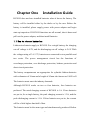
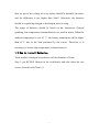
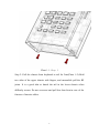
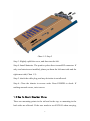
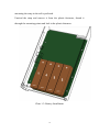
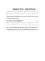
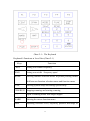
Introduction
KC901S is a multimeter for radio-frequency that supports both vector
network analysis of one port and scalar network analysis of two ports.
With extensional functions of spectrum, field strength and signal
projector, the maximum practicality has been got.
◆Main Features*
The frequency range is as high as 3GHz
The Stepped frequency of entire domain is 1Hz
Good accuracy and stability
Double-conversion and high anti-interference ability
Abundant functions and convenient to carry
The fruits of wisdom of the community **
◆Main Functions
Transmission measurement (filter adjustment, amplifier measurement and
directivity measurement of antennas)
Reflection measurement (adjusting impedance matching network and
examining quality of antenna feed system)
Measurement of Low frequency signal source and radio frequency signal
source
Spectrum display and field strength detection*** (inspecting radio station
emission performances and searching for interference sources)
◆Recommended Applications
1
KC901S is designed for adjusting RF circuits, such as filter, amplifier,
splitter, combiner, for testing input and output impedance, evaluating the
quality of antenna feed system, and for detecting signal amplitudes of
equipment at all levels. In some bands, field measurement, and detection
of interference are allowed.
When combined with community exchange, KC901S is a good tool to
learn radio frequency knowledge. In the area of expertise, it can be
applied
in
professional
Communication
Engineering,
antenna
manufacture and daily maintenance of broadcast and TV radiating
stations, promoting working efficiency, ease carrying burden as well as
improve quality of works.
◆Acceptance and Check
When receive the product, it is necessary to confirm the integrity of
package. First step is to read introduction of user manual and check the
equipment.
A standard packing includes:
KC901S 1
Charger 1
Strap
1
User manual 1
Check up all items, and make sure of no damaged appearance. Examine
whether screws of KC901S loose and unusual sound heard when
2
shaking.Without any exceptional cases, the charger should be connected
before starting up. If the battery is installed, press POWER for 0.5 second
for start-up inspection.
◆Safety Notes
KC901S is not a kind of consumer goods, so the users should be
professionals or be acquainted with professional knowledge of this field.
In this user manual:
Notice indicates inaccurate measuring results or ordinary risks.
Warning
indicates possible personal injuries, serious risks, equipment
damage or other serious consequences .
Warning
When water intake, unusual sound, or other obvious abnormal is observed,
do not start it up.
During thunderstorms, it must not be used to measure any outdoor
equipment including that with lightning arrestor.
Pay attention to grounding of DUT to prevent electric shock.
Equipotential touching is necessary before connection to avoid unequal
potential damages to the apparatus and DUT.
Charging must be under surveillance. It must be far away from
inflammables and explosives when working or charging. Do not cover the
equipment or charger.
Take notice of the temperature range of storage and usage. Do not place it
3
in the vehicle under sun exposure.
KC901S must not be used for any illegal purposes. People with intrusive
electronic equipment should use it with caution. It is better to avoid using
it in hospitals, airports and other sensitive positions.
KC901S must be carried with when the user takes a plane. Make sure that
the antenna is taken off, field mode is set and power is off. Please obey
the local laws and any specific rules in the airport.
The maximum battery capacity of KC901S is 60Wh. It is necessary to
choose qualified batteries and to be careful of the risk of lithium battery.
Please place it out of the reach of children. When KC901S is lent, the
user should urge the borrower to read user manual and inform the
borrower of safety notes.
◆Important Statement
KC901S is not a commercialized product that meets the demands for
appearance and details of all users. The manufacturing technical indexes
and the third party certification affirm the designing and manufacturing
capability rather than provide any guarantee for users. Even though we
have done our best to make it practical, convenient and useful, defects
still exit. We are willing to take your suggestions.
To the full extent of the law, Kexinshe is not responsible for the loss
beyond the prize of KC901S under any circumstances. We take no
4
responsibility for any indirect loss and losses in terms of time, business,
inconvenience, profit and abuse. Maintenance, replacement or returning
product and refund are the only remedial measures we can take. Kexinshe
only take responsibility for the product within the guarantee period.
Under any circumstances, we do not guarantee its applicability, reliability
and security for purposes of commerce, industry and military. We do not
admit any promise made by dealers.
*
Please read technical instruction.
** Support communities:bbs.kechuang.org , hellocq.net
*** Informal function
The lasted version can be downloaded in measall.com
5
Chapter One
Installation Guide
KC901S does not have installed batteries when it leaves the factory. The
battery will be installed either by the dealer or by the user. Before the
battery is installed, please supply power with power adapter and begin
start-up inspection. If KC901S functions are all normal, shut it down and
pull out the power adapter, and then install batteries.
1.1 How to choose batteries
Lithium-ion batteries apply to KC901S. For a single battery, the charging
cut-off voltage is 4.2V, and the discharging cut-off voltage is 2.6V. With
the voltage rating of 3.6-3.7V, batteries are connected in two parallels and
two series. The power management circuit has the functions of
overcharge protection, over-discharge protection, balance protection and
short-circuit protection.
The battery compartments are appropriate for cylindric lithium batteries
with a diameter of 18mm and a length of 65mm also known as 18650 cell.
The batteries must meet the industry demands.
Although KC901S works on two or four batteries, four batteries are
preferred. The rated charging current of KC901S is 1A. If two batteries
are put in, for a single battery, the peak charging current is 1.2A, and the
peak discharging current is 1.5A. If four batteries are put in, the current
will be a little higher than half of that.
The batteries must be the same type and simultaneously produced. Before
6
they are put in, the voltage of every battery should be basically the same,
and the difference is not higher than 50mV. Otherwise, the batteries
should be equalizing charged or discharged prior to using.
The usage of batteries should be based on the instruction. General
speaking, low temperature resistant batteries are used in winter. When the
ambient temperature is over 45 ℃, the battery temperature will be higher
than 65℃ due to the heat produced by the circuit. Therefore, it is
necessary to choose high temperature resistant batteries.
1.2 How to Install Batteries
Tools needed: a hexagon screwdriver with the diameter of 2mm
Step 1: put KC901S flatwise in the workbench, and take down the two
screws from the tail( Chart1-1).
7
Chart 1-1:Step 1
Step 2: Pull the chassis from keyboard to tail for 2cm(Chart 1-2).Hold
two sides of the upper chassis with fingers, and meanwhile pull the RF
joints. It is a good idea to knock the tail in the lower chassis when
difficulty occurs. Do not overexert and pull less than 4cm in case of the
fracture of interior cables.
8
Chart 1-2: Step 2
Step 3: Slightly uplift the cover, and then turn the left.
Step 4: Install batteries. The positive poles direct toward RF connector. If
only two batteries are installed, please put them the left-most side and the
right-most side( Chart 1-3).
Step 5: check the cable plug, and any deviation is not allowed.
Step 6: Close the chassis in reverse order. Press POWER to check. If
nothing unusual occurs, twist screws.
1.3 How to Mount Shoulder Strap
There are mounting points in the tail and in the top, so mounting in the
both sides are allowed. If the user needs to use KC901S when carrying,
9
mounting the strap in the tail is preferred.
Unwind the strap and remove it from the plastic fasteners, thread it
through the mounting points and lock in the plastic fasteners.
Chart 1-3: Battery Installment
10
Warning
The standard strap is appropriate in usual occasions. Extra preventing
falling measures should be taken when working at heights like towers or
ladders.
1.4 How to carry and hold
After the strap is adjusted to an appropriate length, the user should sling
over it or wearing it straightly. If KC901S is used in movement, it is
suggested that the user hangs it upside down. The strap should be shorten
and slung over shoulder when running with it, and prevent injury to the
body.
KC901S is designed to be held with left hand and be handling with right
hand. When standing to operate, the user holds the left hand at the
upper-left, thumbs the knob and places the bottom against the stomach.
At the same time, the user connects cables and plays keyboard with the
right hand.
The knob is not necessary, because keyboard offers all the functions. “+”
“-” equal to rotating knob, and ENTER means pressing the knob. The
user holds the bottom of liquid crystal with both hands and plays the
keyboard with thumbs.
Fix KC901S in the workbench with screws through mounting points.
11
Chapter Two
Quick Guide
Designers have tried their best to make users understand easily. Users who
have some basic knowledge can handle it in a short time. Therefore, this
manual does not demonstrate every detail as usual, but only explains
some points that are special.
2.1、Power Switch and Keyboard
Chart 2-1 shows keyboard functional layout of KC901S. Press POWER
at the bottom left for 0.5 second to start up or shut down. After the boot,
the test mode showing and the main setting are consistent with the
settings that were used last time. The menu displays items related with
the current mode.
12
Chart 2-1:The Keyboard
Keyboard’s Functions at Level One (Chart 2-1)
Keys
Functions
CENT
Setting scan central frequency
SPAN
Setting scan width(frequency span)
MODE
Entering function selection menu. Repeated pressing means
shift between function selection menu and function menu.
FUNC
Entering system setup and exiting system setup
STOP/RUN Stopping scanning and starting scanning
+、-
Equal of rotating knobs with larger stepper
MARK
Entering the cursor function menu
AMP
Adjusting reference level, trajectory position and range at
13
signal source function
POWER
Power shift
SHIFT
Starting functions at level two
Chart 2-1
Keyboard’s Functions at Level Two (Chart 2-2)
Keystroke
Functions
Combinations
SHIFT+CENT
Setting starting frequency
SHIFT+SPAN
Setting stopping frequency
SHIFT+LOCAL
Disconnecting from the computer and forcibly
switching to the local operating system
SHIFT+FUNC
Resetting to defaults
SHIFT+STOP/R
Switching to single scan. Under this circumstance each
UN
pressing on STOP/RUN means scanning once.
SHIFT+1
Saving data into the memory card
SHIFT+2
Reading curves and settings from the memory card
SHIFT+4
Adjusting screen brightness
SHIFT+5
Adjusting RF output amplitude
SHIFT+6
Key notification tone on/off
SHIFT+ENTER
Locking the keyboard and knobs
Chart 2-2
2.2 Measuring Ports
14
There are three measuring ports in KC901S. Two of them are
external RF ports, and the other is AF port. The most right one is the
output port of frequency sweep signal source. The most left one is the
input port of tracking receiver. The other RF port inside has been
connected to standard load that is replaceable.
Output port
Input port
Output port
Rotate/ Press
Chart 2-4: The Top ports
Referring to Chart 2-4, Port 1, Port 2 and Port 3 are from the left to the
right.
The interfaces of “N ” are precision, so more attention should be paid to
protecting these ports, especially S11 in the most right. Careful
examination and repair are expected done before well-made connectors
are linked. However, it is useless to connect switch-overs that reduces
accuracy.
15
The ports are designed to be pulled and plugged for 500 times. Replace
them with new ones as soon as the life ends in case that vector
measurement is affected.
2.3 Auxiliary Ports
There are three interfaces in the right as following: Power input, data
interface and SD card interface (chart 2-5).
Chart 2-5: The Right Interfaces
2.4 Function Description
Six basic functions of KC901S: reflection test(S11) , transfer test(S21),
spectral view(SPEC), filed intensity(FILED), RF signal source (RF
SOURCE), and audio frequency signal source ( AF SOURCE).
MODE is used to select function. The equipment shifts between function
menu and function selection menu by using MODE a couple of times. In
16
most cases, MODE, equal to “HOME”, turns the screen back to the
function menu or function selection menu, so it is frequently used.
The typical application of Reflection Measurement (S11) is measuring
the standing wave of antenna. The right port should be chosen.
Reflectometer is a kind of vector function with various display modes,
selected in FORMAT menu. In Smith Chart and impedance display, the
second soft menu from the left provides more display modes.
Access: press MODE and then select (S11). (FORMAT)in the soft menu
decides the display mode of measuring result.
The typical application of S21 is measuring amplitude-frequency
characteristics of filter or amplifier and gains of antenna. The right RF
port is to output signal, and the left one is to input.
Access: MODE and then press S21.
Insertion Loss Measurement is a special type of transfer measurement,
characterized by high respond speed. As a result, it applies to the fine
tuning of filter and measurement gains of antenna.
In order to keep consistence with the operating habits of ordinary
receivers, the entry into Insertion Lost Measurement is set in Field mode.
Access: firstly MODE, and then press FIELD, finally press Insertion to
make “GEN ON” appear.
The typical application of SPEC is monitoring the occupancy and the
interference of band and adjusting circuits producing RF signals except
17
45 MHz。KCSA-R100 is connected to find unidentified emission source.
Access: MODE and then press (SPEC).
FIELD applies to not only measurement field strength coverage but also
searching the amplitude of RF. The port of KC901S is capable of DC
isolation so as to externally connect probes to directly search the signal
value of receiver and transmitter. It is necessary to match impedance and
concatenate attenuator when detecting transmitter. As long as experiences
are got, FIELD is used to detect emission the radio station to find fault in
time.
Access: MODE and then press FIELD.
RF SOURCE produces a millwatts signal, with an application of
transmitting weak signals to the air to determine the sensibility of radio
station from a close distance, particularly the sensibility of relay station.
It is handier to use the small signal for experienced users. More externally
connected attenuators further develop the applications of signal source.
To some extent, RF Source can adjust the signal level with the help of
built-in attenuator. The output attenuator plays the role as an amplitude
modulator to carry out ASK. If the output attenuator has been applied to
adjusting output range, the used decrement which has been used is unable
to modulate. As a result, the modulation degree conflicts with the output
attenuation. When output attenuation increases, the modulation degree
that can be used reduces.
18
Access: Press MODE to select NEXT, and then press RF SOURCE in
menu.
AF SOURCE produces a low frequency signal with a typical function of
adjusting the voice-grade channel of electronic equipment. Because AF
SOURCE, with various modulation modes, produces the firm output of
50MHz, it is used to adjust RF circuits under 50MHz.
In actual, AF SOURCE can be set in a high frequency (but does not
guarantee indices). With the help of its harmonic wave, it can be used to
debug the sensitivity of radio stations.
Access: Press MODE, and then select AF SOURCE in menu.
2.6 Local Oscillation Mode
The Local oscillation in SPEC, S21 and FIELD is used to judge mirror
effects.
Low Lo: low local oscillation. If local oscillating frequency is lower than
the measured frequency, mirror-image jam is caused by the lower
frequency.
High Lo: high local oscillation. If local oscillating frequency is higher,
mirror-image jam will be caused by the higher one.
19
If a signal appears in the same position whatever the local oscillating
mode is, it is likely to be there already. If it disappears in any mode, it
must be false. Appearing on the low Lo while disappearing on the high
Lo, the signal frequency is determined by subtracting 90MHz from the
appearing frequency. Appearing on the high Lo while disappearing on the
low Lo, the signal frequency is determined by adding the appearing
frequency and 90MHz up.
If the height of background noise differs in modes, the priority is the
lower one.
Local oscillation mode is ineffective below 100MHz .
Notes
Factory calibrations of SPEC , S21 , FIELD are operated under the high
local oscillation mode. Under the low oscillation mode, a small
measuring error may occur.
2.8 Filed Strength Mode Setting
The actual measurement is the level of input port. By inputting the
electrical level and calculating antenna factor, the field value will be got.
Antenna factor is mainly relevant with frequency and antenna gain. The
equipment should get the antenna gain in order to know the accurate
reading of field.
After enter the FIELD mode, the user should press ANT GAIN on the
20
right side. Firstly Select “ +/- ”,and then input the antenna gain on
numeric keyboard.
The item in the middle decides the refresh time of reading in levels of
FAST, MIDDLE and SLOW. MIDDLE is recommended. The refresh
time of Table S not disturbed by the setting is used to observe
instantaneous changes of signal intensity.
Warning
KC901S is a network analyzer which does not prevent the reveal of local
oscillation. When it is used to observe spatial frequency spectrum and
field strength, local oscillation signal will flow backwards to receiving
antenna. The strength may arrive -10dBm, and the frequency will be
45MHz higher or lower as the receiving frequency. Consider
consequences are caused by the sending signal, and take some measures
for protection. Always switch unit off or press stop to prevent other
systems from RFI when you have finished measurements!
2.9 Insertion Loss Mode
Insertion loss is the system of single frequency point of S21. It is an
essential measurement of S21, whereas only a single point frequency is
measured.
After entering the FIELD test mode, Insertion on the right of the menu
means starting signal input. Get to GEN ON into the display of insertion
21
loss measurement. On the left of the screen, the user will see that the
reading is still an absolute level value. While on the right, it has been
relative value. Connecting the RF port with measuring cable, the user
selects AUTO CAL to adjust the relative level value into zero. Next, the user
links testing cable to the measured device. Now, the reading on the right
side is the value of insertion loss.
2.10 Data Storage
Plug in SD card to save data.
In measuring function, press SHIFT+ 1 to save current screen capture.
Save measuring results and settings in numerical table.
When the computer is connected with USB cable, KC901S will be a
virtual USB flash stick. Under such a circumstance, the computer takes
over SD card, therefore data could not be saved when the computer is
connected.
Under S11 mode, S1P format file as well as all original measuring points
should be stored on (smith chart) mode.
22
Chapter Three User Calibration and
Preparations before Measurement
3.1 Overview
Normalization of KC901S’ ports has been finished before leaving factory,
therefore direct use is allowed in most cases. The curve may deviate after
power on in the field because of various reasons. In common engineering
applications, it is not necessary to calibrate KC901S as long as the
measuring result is helpful to analyze and solve problems.
Cables and a great number of connectors, indispensable to measure, cause
insertion loss. With time going by and the temperature changing,
performance of KC901S may drift. All those disadvantages have negative
impact on measurement, the user can do calibration as occasion requires.
If conditions including cables and temperature change, error may occur
during calibration. As a result, it is better to make measuring conditions
23
the same with calibration conditions. In other words, calibration
conditions should be as close to measuring conditions as possible.
3.2 Calibration Modes
There are three kinds of calibration modes: factory calibration, system
calibration and user calibration.
Factory calibration: high-density calibrations of all frequency ranges have
been done before KC901S leaves factory. Calibration scaling algorithm
operates a higher-density interpolation. After factory calibration, basic
errors can be corrected in any frequency, so generally no calibration is
needed. Factory calibration data saved in KC901S can not be reset and
directly used by the user. Factory reset function sends the data to system
calibration.
System calibration: The same density with factory calibration, but it
allows self-operation by the user. Factory reset leads to system calibration
data being covered by factory calibration data.
User calibration: calibration can be operated by the user at any time. This
calibration whose accuracy is higher than that of factory calibration and
system calibration corrects every data point without interpolation error.
User calibration only takes effect on set frequency. If setting parameters
are changed, the calibration data will make no sense. The final calibration
data will be temporarily saved and the data takes effect back to the final
setting parameters.
24
Calibration Operation
Under any display mode of functions of S11 and S21, CAL Select in the
rightmost of the menu is used to switch among system calibration, user
calibration and closed calibration.
Re-select RE CAL to operate user calibration if necessary.
Press SHIFT+7 into system calibration in FUNC menu.
KC901S prompts operational approach in calibration mode.
3.3 Calibration before S21 Measurement
If DUT is small and light, one of the ports can be directly linked to the
equipment, although it is not a good habit. On that occasion, one more
cable constitutes measuring system. If DUT is big or the connectors do
not match each other, two RF cables are used.
Chart 3-1A: Connection with one cable
As for one cable, it should be bridged over the two ports before
measurement (Chart3-1A). As for two cables, them should be connected
25
with a connector with good quality and bridged over the two ports (Chart
3-1B).
Chart 3-1B: Connection of Two Cables
If many series cables in different locations appear in on system, a one
time series calibration is suitable.
When testing power amplifier, connect an attenuator with the output port
in series to avoid damage. If it is a little signal amplifier, connecting an
attenuator with the input port in series is imperative to avoid strong signal.
Before that kind of measurement, it is suggested that all the attenuators
should be connected with cables in series to operate calibration.
26
Follow the hints of Re CAL in function menu to start user calibration.
If frequency is changed after calibration, the system calibration
parameters are automatically used.
3.4 Calibration before S11
Measurement
Although there are many display modes in S11 function, only one
calibration is necessary, because the same data is being shared in all
modes.
It is necessary to operate user calibration in these following cases:
1. In acceptance measurements for important antennas, for example,
antennas of radio and TV emission stations.
2. Failing to be connected to KC901S, the port under measurement
should be linked with extra cable.
After calibration, please check whether the curves are in the proper
position in the open-circuit and loading. In VSWR mode the curve should
be higher than 10 in open-circuits, and it should be lower than 1.2 with
standard load of 50 Ohms with good quality.
Notes
In the far-end calibration of external cable, if electric length of the
external cable is longer than the half of STEP wavelength, scan points
should be increased or SPAN should be reduced before calibration. For
example, 3MHz stepping equals to 100m wavelength, and the external
27
cable is not longer than 35m(electric length=the actual cable length
/speed factor)
Select Re CAL under S11 mode and follow the steps given.
3.5 Reflection Standard Implements
S11 adopts SOL calibration, so three standard implements are needed:
Short, Open and fictitious load. During the calibration, these three are
considered ideal. KC901S looks for distinctions between ideal value and
actual value describing all errors with equations. Therefore, the three
standard implements should be as close to ideal conditions as possible.
KC951011/KC951012 is a commonly used standard implement offered
by Kexinshe. Users can choose other proper standard implements, being
aware that the terminal effect should be small because of no
compensation provided by KC901S. The nominal electric length of
KC951011/12 is zero. Type the actual electric length in FUNC if you
want to use the offset calibrator.
Connect the standard load to the equipment with all the effort. Do not
overtighten the connectors.
Standard load is a valuable accessory. Careful using properly keeping and
regular checking should be done. Before calibration, please check and
clean the connectors to prevent damage from the load or from the
28
connectors of KC901S..
3.6 Necessary Preparations
3.6.1Check up battery power before brings the apparatus on the go. Start
up KC901S to observe voltage. If voltage>8.0V, it means that the rest
power is more than a half. It is strongly advised to set auto power off in
case that the battery runs out. For long hour’s outdoor work, either a
charger or a vehicle power supply connector should be used. In wildness,
a external battery pack is needed.
3.6.2 KC901S should be carried with a waterproof suitcase to prevent
from rain and water. The specialized suitcase for KC901S is advised.
3.6.3 Proper attenuator should be prepared for measuring transmitter and
amplifier. When the measured signal exceeds the limit, attenuator must be
connected in series.
3.6.4 When testing antenna in places with lots of antennas, a terminal
wattmeter is used to measure inductive power of the antenna which
should not be more than 0.1W. Many times, several sets of antennas are
concentrated on the same tower, inducing strong transmit power through
space coupling .Too strong RF power induced from the antenna under
measurement are bound to burn down the equipment.
3.6.5 If short-wave antennas are erected near high voltage lines and sub
stations measurement induced voltage, not more than 15V, with
29
multimeter Alternating Current .It is strongly suggested that the shield of
coaxial line should be grounded nearby.
3.6.6 If RF signal of circuit board is measured by a probe, outside
protective shield of measuring cable should be connected with ground of
the circuit. It is dangerous to do suspension measurement that may burn
out KC901S and board under measurement.
3.6.7 KC901S can be used during charging, but measuring active devices
should be avoided. If the measurement is inevitable, an equipotential
bonding between ground of KC901S and ground of DUT is needed to
avoid damage from DUT and the equipment.
3.6.8 The standard strap is only suitable for general use. Firm safety rope
and packing bag should be prepared for working in height to avoid
accidental falling. Set a warning region below the tower when someone
works on it.
30
Chapter Four Common Measurement
Methods
4.1 Quick Adjustment of Diplexer
A duplexer is an important part of a repeater. The insertion loss and
isolation ratio of a duplexer are directly relative to the overall function of
a repeater. KC901S can provide an isolation of exceeding 100db
operation range under regular VHF/UHF frequency band conditions and a
duplexer can be adjusted at its optimate state under the supervision of
KC901S.
Prepared accessories for usage: A fictitious load 50Ω, 2 RF Cables
and necessary RF connector assembly.
It is preferred to fix KC901S on the workbench.
Adjustment tools: socket wrench with center hole, screwdriver. Fix the
be-adjusted diplexer on the workbench if possible.
Special setting: employ intermediate speed or high speed(FUNC,
31
Speed)in initial adjustment. Employ low speed or insertion loss mode in
precise adjustment of notch points.
Here is an introduction of adjustment steps by taking six-cavity duplexer
as an example that works on the principle of notch filter.
Adjust the KC901S to S21 mode, and adjust the center and span of the
apparatus so that frequency band can cover the original frequency and
new frequency of duplexer. The AMP can be adjusted to 0dB or +10dB
(change the AMP and ordinate span according to the position of curve.
When the ordinate span reaching 20dB/div). Then start system calibration.
Move mark1 and mark 2 respectively to near the new receiver frequency
and transmitter frequency.
Please use the equipment to measure the insertion loss (S21) RF cable
first, then sway connection cable and connector lightly to look at if the
curve dithers while measuring in order to make sure there is no poor
contact. The insertion loss of cable should be as small as possible. The
quality of cable should be good enough to provide with excellent screen.
Hang cables in the air to observe the position of noise floor for a
minimum of -90dB at 450MHz.
Clean the socket of the duplexer, then connect the output port
of
KC901S to the TX in-port of duplexer(usually marked “high”), next
connect the in-port of the apparatus to the ANT(antenna) port, and
connect the fictitious load to the RX output port (usually marked
32
low)(chart 13).
Fictitious Load
Duplexer
Chart 4-1:Example for Connection Method of Duplexer Measurement
Adjust the three screws near the TX port to move the trough to mark1
indicated position until they overlap. Then take turns to slightly adjust
screws under the supervision of S indication until the reading is the
minimum (the maximum negative). Normally, the reading should reach or
exceed-60dB. At this moment, mark1 means the HIGH isolation ratio and
mark2 means the HIGH insertion loss
33
Connect the output port of KC901S to ANT port of duplexer, still connect
the in-port to the RX port, and connect the fictitious load to the TX port.
Adjust the three screws near the RX port to move the trough to mark2
indicated position until they overlap smoothly. Then repeatedly adjust the
three screws from center to RX side until the mark2 indication is the
minimum (the maximum negative). Normally, the reading should reach
-60dB.
If necessary, reset the CENT, REF of the equipment and reduce span so
that the new frequency curve can be partially enlarged. Adjust the
mark1,2 position more accurately At the meantime, connect measuring
cable with straight thread connector to go on with S21 through
calibration.
Reconnect the output port of equipment to TX port of duplexer, and then
link the in-port to ANT port, finally connect the fictitious load to the RX
port. Next repeatedly adjust the three screws from middle to TX side to
keep the mark1 minimum reading. Normally, the reading should exceed
-70dB, good quality duplexer can reach -90dB. At this moment, the S
reading of Mark2 means the insertion loss of duplexer transmit signals.
34
Stepping
Sweep Bandwidth
Level
Curve
keeping
LOW
Center
el
Local
oscillation
Re-calibration
System
calibration
Calibrations
Chart 4-2: Typical curve of LOW side of duplexer, uncompensated cable
loss
Connect the output port of KC901S to ANT port o. Then connect the
fictitious load to the TX port. Slightly adjust the three screws near the RX
side to keep the mark2 minimum reading. Normally, the reading should
be less than -70dB, Read the S reading of mark1, which means the
insertion loss of duplexer transmit signals.
Please switch local oscillation mode, choosing the lowest way in the
curve bottom. Adopt different local oscillation modes when measuring
both parts of the duplexer.
Sometimes the two sides reading data of duplexer affect with each other,
so it is necessary to adjust the three crews repeatedly until the restrain
35
reading data reach or exceed -70dB.
Do not adjust the restrain curve of the duplexer into a too sharp shape.
Reduce SPAN to 1MHz, observe the bottom of the curve, the width
should exceed 100 KHz. If the curve is too sharp, the cusp of the curve
may move out the used frequency while the temperature or the match
condition of ANT is changing.
If there is a contradiction between insertion loss and attenuation,
attenuation on the RX side should be primarily guaranteed. Appropriately
turn down the transmit power so that to reduce the requirement for
attenuation. This should be abided by the principle of “Adjust TX toward
inside and Adjust RX toward outside”; try to keep balance of insertion
loss.
For the duplexer whose coupling degree can be adjusted by screw, adjust
the coupling screws. If all adjustable screws are not long enough, change
them to long screws. If the entering length of screws is too long, the Q
data of duplexer will be lowered. Dismantle the extended solenoid of the
duplexer in case of emergency.
If the insertion loss can not be turned down, S11 measurement can be
tried (connect the fictitious load to the non-tested port rather than to the
in-port of the apparatus). Tentatively adjust and compare the reading with
others, try to control the SWR under 1.5dB.
Please screw and fix the screws during the adjustments to keep the
36
reading data stable.
Notes
Port match has influence on the rejection characteristics. Measuring
results are influenced by the type of apparatus used and the relationship
between the equipment changed and ports of the deplexor. The antenna
impedance changes as repeater is different, so practical performance falls
behind expectation. Draw lessons from practical performance after
installing repeater in the first adjustment.
Connect in tandem an attenuator (around 10dB) in the input port to
improve the match. Increase output attenuation(SHIFT+Po.ATT)to 10 or
20dB, which is helpful to reduce influences on measuring results by
non-linearity.
4.2
ANT Measurement
Warning
It is possible for the output port of KC901S to a maximal outputs 10dBm
(10mW). KC901S transmits the output into the air in ANT measurement.
Po.ATT increased can reduce emission, but Re CAL should be done.
4.2.1 SWR Measurement for ANT
When ANT is to be measured, the equipment should be adjusted to S11
mode, and Format is VSWR. Settle down center and span, the operator
should be away from ANT.
37
The SW of AN is easy to be affected by the surround environment. So it
is better to choose a wide outdoor field, such as a rooftop. The length of
the feeder should be as short as possible, disconnect the feeder from the
end which connects the ANT. Contain the feeder for calibration.
4.2.2 Cable Deduction
In measuring antenna, occasionally, calibration can not be done on the
port of antenna, so the influence from feeders can not be automatically
dispelled. On this occasion, reflection parameters of antenna send the
condition of cable to KC901S, the equipment deduces cables.
In FUNC menu, there are two set items: cable electric length and cable
attenuation. Cable electric length =Cable length/ velocity factor. Cable
attenuation is estimated based on the attenuation at unit length presented
in technical manual and cable length.
The two items above are both single-pass parameters.
Cable deduction is employed in low frequency under 30MHz.If
conditions permit, operate user calibration on cable’s far side, because the
equipment can eliminate the influence of cable.
4.2.3 Antenna Impedance Measurement
KC901S works out the impedance of antenna by measuring amplitude
difference and phase difference of incidence signal and reflection signal.
Because both amplitude difference and phase difference are related to
feeder. Operate user calibration in the feeder’s far side unless antenna
38
is directly connected with the equipment.
The impedance is greatly affected by installation of antenna. During
measurement, make the installation condition get as close to operating
environment as possible. For antennas installed in interphones and routers,
shells should be contained during measurement. Antenna of router should
be measured together with the mainframe. Firstly, the original cable is cut
from inside of router. Secondly add a measuring cable for the antenna.
Thirdly, the side close to antenna passes through magnetic ring. For
example, measuring in calibration, these parts of cables should be
contained.
At low frequency, if cable is not included in calibration, set cable’s
electric length to deduce its influence. At high frequency (for example
2400MHz), it is not a reliable solution.
4.2.4 Measurement for Antenna Gain and Antenna Pattern
Utilizing the function of S21 (or insertion loss) of KC901S, together with
another set of antenna to obtain the horizontal antenna pattern or back
ration. If there is another set of known-antenna gain antenna, then the
antenna gain can be measured.
Measuring environment: black rooms or standard measuring locations. A
level open area, the size should be larger than 20 times of the wavelength.
For the antenna of over UHF frequency range, smooth and level rooftop
can also be the measuring environment.
39
Equipments: 2 antenna supports, one has a rotary table, if the condition is
limited, rotate the antenna support manually. The height of the antenna
supporters should suit to the designed usage conditions of antenna. By
principle, the height should be longer than the 2 times of working
wavelength. It is better if the distance between the two antenna supports
is larger than 10 times of the working wavelength.( For example, the very
long working wavelength of antennas of short wave, it is allowable to
appropriately decrease the distance between the two antenna supporters ).
If necessary, take more times of tests by changing the distance, and take
the average number to eliminate the impacts cause by ground reflection.
According to the distance between the two antenna supporters, prepare
long enough cables; try to keep the equipment and tester a distance more
than 10 times of wavelength form antenna. Besides to-be-tested antenna,
prepare another known-antenna gain antenna for reference.
Method: Install measuring antenna and to-be-measured antenna on the
supporters (Chart 4-3). At first, make certain direction of to-be-measured
antenna (predict the main flap direction or mark a direction) aim at the
measuring antenna, then set the apparatus S21mode and input measuring
frequency. Normally, choose the smaller span such as 1MHz.
Furthermore calibrate the apparatus, turn the curve sheet into zero. Next,
rotate the to-be-measured antenna with a certain angle at intervals. Write
down S reading (dB number). At last, draw dots on the angle- antenna
40
gain graph thus to obtain the direction graph of the to-be-measured
antenna.
The above measurement can also be done by utilizing insertion loss
measurement mode. At first, set FIELD mode, select (Insertion)to
start insertion loss measurement, then press Auto CAL button to turn the
insertion loss reading into zero. The insertion loss reading means the
same as the S reading in S21 mode.
Measured antenna or
the standard antenna
Referential antenna
Distance larger than 10 times of the wavelength
Coaxial cable
Rotatery control cable
Antenna rotatery station
Antenna supporter
Angle indicator
Chart 4-3, Antenna gain measurement in an open area
In the measurement, press SHIFT+1 to save data to analyze afterwards. In
order to decrease operation complexity, KC901S automatically names
files in chronological order. The user can make notes of starting time and
quantity to avoid confusion.
If the user wants to measure the antenna gain, it is necessary to install the
known-antenna-gain antenna for reference unto the to-be-measured
antenna supporters, adjust the orientations of the referential antenna and
testing antenna(make the referential antenna’s given direction aim at the
measuring antenna ), then go on user calibration under S21 mode. Then
41
keep the settled reading of the equipment invariant, and then change the
referential antenna into the to-be-measured antenna to measure, write
down the reading of different angle S reading. At this time, the obtained
reading plus the referential antenna gain, this is the antenna gain of
different angles.
If many frequencies direction graphs and antenna gains should be
measured, repeat the above steps by changing the different frequencies.
During measurement, do not change frequency, otherwise user calibration
loses efficacy and the data lose its relative significance. While measuring,
the user keeps away from the antenna, if it is necessary to rotate
to-be-measured antenna manually. After rotation, the user should walk
away from the antenna and then read the reading data.
Use two KC901Ss; setting one signal mode, another one FIELD mode,
this helps to build a single frequency point scalar net measurement
system, used in the setting of 2 far distant antennas. Of course, the one
KC901S for transmit can be replaced by a transmitter of good stability. If
broader measurement range is needed in other S21 measurements, two
KC901Ss can be controlled by one computer.
4.3 Measuring Electric Length of Transmission Line
KC901S precisely measures the electric length of transmission line
terminal in short circuit or open circuit. In S11 mode, take a smooth and
periodic part of curve to measure frequency difference(Δλ)of a circle of
42
phase shifting in PHASE display. The electric length= Δλ/2.Certainly, the
electric length= Δλ (phase shifting of 180°)/4. Additionally, the electric
length can be got from the frequency difference of double 360°phase
shifting.
Besides, deal with the derivatives based on the stored data on computer to
get group delay. In this way, electric length will be calculated. Take
narrower SPAN or more scan points to avoid phase aliasing.
Take SPAN as narrow as possible to make the curve experience one or
two periods in order to get a higher range resolution.
It is necessary to operate user calibration on the edge of transmission line
when connecting transmission line under test via patch cord. The
compensation of cable length in FUNC menu should be set as zero.
In Chart 4-5, electric length=1.432m,cable length=1.005m. It can be
calculated that velocity factor is 0.7018.
43
Reflection
Stepping
Phase frequency
Characteristic
Center
Curve
keeping
Scanning
width
Display
mode
System calibration
Re-calibratio
n
Calibrations
Chart 4-5: Measuring Electric Length in Phase Frequency Characteristic
In short-circuit and open-circuit, cable loss is about half of return loss.
When cable is connected with antenna, return loss at non-working
frequency can be used to estimate cable loss.
4.4 Spectrum Display
KC901S strengthens properties of the input channel to provide the basic
spectrum display.
Warning
The input port of KC901S permits a limiting level of +20dBm and a
limiting DC voltage 15V. The apparatus is bound to get damaged if the
standard is disobeyed. When measuring transmitter and amplifier, an
appropriate attenuator must be concatenated to control the limiting
values.
44
Notes
+20dBm is the limiting level not damaging the apparatus, which does not
mean that KC901S is able to measure the signal at +20dBm. The proper
level is less than +10dBm for the sake of accurate measurement.
KC901S is a network analyzer, so the measuring result of spectrum is
only for reference.
Mirror image interferes with the spectrum mode. Connect an appropriate
filter to the input port in series to operate monitor function. When
measuring shortwave spectrum, use (Local Mode) to identify image
response. Cascade KC9504.01 of 120MHz to eliminate interference from
intermediate frequency feed-through.
If the concerned span is too narrow, set CENT and SPAN according to
need. Set AMP based on intensity of the signal under measurement. AMP
<-40dBm when searching for weak signal. Unless conditions permit,
scan piece by piece in narrow span.
4.5 Detecting Interference Source
In bands no interfered by mirror image, use KC901S with directional
antenna to detect interference source by oto method.
After entering spectrum mode, set center at frequencies probably
interfered. Span is set at small value (like 1MHz).
When interference is
weak, REF should be set to -60dBm. Do not stop Adjusting direction of
45
antenna and polarization mode to detect interference signal until the most
obvious bulge emerges in the center of spectra. After measuring the
directional azimuth angle of antenna by magnetic compass trace out
directional line. In the same way, get another line at another point. The
intersection point of two lines is likely to be where the source locates.
Preserve an angle of 60—120,( close to 60 )between the linking line of
two measuring points and one directional line(Chart 4-4) .
Keep the measuring point in height to avoid being blocked by buildings.
When approaching to the source, adjust AMP based on the intensity or
adopt the field mode. Move in the direction of the strongest interference
and keep approaching to the source. Generally speaking, the amplitude
should be over 70dBμ(-37dBm)when approaching to the source.
46
Chart 4-4. An example of cross location and diagramming method
Connect a band-pass filter between the equipment and antenna to the
reliability of measurement. In a helical structure or cavity structure,
band-pass frequency of the filter can be adjusted under the supervision of
KC901S before using. When measuring weak signal, it is practical to
connect a low-noise amplifier between the filter and the equipment.
Locating the interference source is a task combined with theory,
experience and technology no matter what kind of equipment is used.
Practices increase efficiency. Because of diffraction and reflection of
signal, there are many illusory directions in measurements in cities and
mountainous areas.
47
*For narrow-band signal, higher response speed is got when the user
detects interference source in FIELD mode.
*FIELD function is used to measure emission field strength around the
antennas of radio station. IF gain which may be damaged by strong signal
because of wrong setting in SPEC function is manual set.
*Connect a filter of narrow band pass in series to detect interference with
FDM system of 45MHz frequency difference for fear that the local
oscillation reveal interferes with communication system.
Warning
Without permission, do not use KC901S to monitor the spatial frequency
spectrum of non-working frequency. It should not be revealed even it is
measured by accident.
48
Chapter Five Maintenance
5.1、How to Clean Screen, Keyboard and Ports
Please remove protective films from the screen. The glass screen
protector is replaceable, so there is no necessary of pasting screen
protector which could reduce visibility under the sun.
Please clean the dirty screen and keyboard with wet tissue firstly and with
gauze later.
It is a proper way to sweep away the dust inside with 0.2MPa compressed
air after dismantling the control circuit board. On occasion the glass and
rubber pad should be replaced.
RF connectors shall be frequently cleaned with dry swap first and with
anhydrous alcoholic swap later. End faces of core needles and ledges
outside connectors are supposed to be wiped luminously. Twisted tissue is
a good tool to clean up the holes on core needles.
warning
The charger and batteries must be removed prior to dismantling circuit
board. The user actions of dismantling enclosure and circuit board to
install batteries and of cleansing screen do not change the term of
maintenance. However, any fault made during this process is not
guaranteed.
49
It is not allowed to cleanse screen, keyboard and knobs with organic
solvent.
5.2 Other Matters Needing Attention
1. The equipment should be settled inside in a pack or a suitcase during
the long distance transportation. A baldric should be used while on-the-go
to avoid falling off, collision or putting together with other construction
tools. The connector must be removed during transportation and carrying
unless necessary. It is forbidden to use measuring cable as handle.
2. Flexible cable should be used to switch while measuring heavy devices
or connecting thick feeder.
3. While installing the plug-ins, please point the position, plug in
carefully, shake lightly and screw slowly. Screw the thread tightly when
feeling the core needle has been already inserted into the core hole. Both
hands should operate to screw the thread, with one hand holding the body
part of the plug-ins to avoid revolve of the plugs, another hand revolving
the exterior helicoil. Revolve of the whole plug should be avoided,
otherwise lifespan of the RF connector will be dramatically shortened and
also cable will be damaged. Pay attention to check before stalling
plug-ins at construction. If the core needle protrudes too long, curve or
lant, stalling should be done after repair of the core needle, otherwise the
interface will be stretched.
50
4. The equipment should be avoided of being exposed in the rain or water
inflow. The equipment should be put inside the suitcase or be prevented
from rain in rainy days. Turn the power off immediately if clean water
flows in; fling out the water though the bottom part and blow dry it in a
ventilated place. Waterproof suitcase is suggested to be equipped if the
equipment is often in the open air.
5. The equipment should be sealed with plastic bag if the operator enters
in a room with central heating from the outside in winter. If there is dew
formation on the apparatus, firstly KC901S should be put near the
radiator to be dried, and then the equipment can be powered on. But it is
necessary to pay attention to the temperature.
6. It is no good for maintaining good battery life if power shortage
warming appears or power off. A long-term floating is banned. When the
charger is connected for a long time in work, batteries should be
removed.
7. When KC901S lies idle, the battery should be 8.0V for storage. During
that time, it is better to annually charge once at least to 8.0V. It is
suggested to remove batteries before a long-term storage.
8. Do not keep the equipment close to high-powered transmitting
antenna. Do not kept interphone close to transmission.
9. Ionizing radiation may do harm to the equipment. In addition, neutron
irradiation makes irreversible damage.
51
10. The USB socket is fragile. Use Soft data cables to avoid lateral force.
11. Period of verification of KC901S is one year. It is better to send it to
manufacturer for calibration and verification.
12. The warranty period for the host is one year. Any exterior damage
which is caused by normal wear and tear or artificial damage is not
included in the quality warranty after delivery.
12. It is forbidden to dismantle the case arbitrarily during warrant period.
Damage caused during the tear-down is not included in the quality
warranty. Attempt to disassemble RF components can void the warranty.
52
Chapter Six Technical Notes
6.1 Measuring Principle
The measuring circuits of KC901S consist of one signal source and three
receivers.
The signal source is divided into two frequency bands: the one lower than
50MHz ( AF signal source lower than 50MHz)is directly produced by
DDS; the other higher than 50MHz is produced by PLL. The two
frequency bands pass through one gating switch converging into one RF
signal.
Two of the three receivers are relevant applying to S11 measurement,
while the other applies to measuring S21 and frequency spectrum.
Negative coupling
Positive coupling
The first
frequency
mixing
The second
IF
Detection
computer
Data interface
Application
processing,
Display
53
Phase demodulation,
Detection
Chart 6-1. The Functional Block Diagram of KC901S
When S11 is measured, CW produced by signal source gets positive
signal from positive splitter prior to getting negative signal from the
bridge, and finally it output from port 3. Phase difference and amplitude
difference are got after the positive and negative signals enter two
receivers separately, via double-conversion, to phase demodulation and
detection circuit. Adopting counting method to do digital phase
distinguishing, KC901S measures amplitude with logarithmic detector.
All data about S11 is got from phase difference and amplitude difference.
When S21 is measured, signal source still output from port 3 via the
bridge, but no detection is taken before it passes through DUT. Next, the
signal inputs into port 1 to undergoing a frequency conversion and an IF
amplification. The absolute value of level is got via amplitude wave
detector. The result of transmission measurement is got after a
comparison between testing data and calibration data (transmission data
recorded by KC901S).
In AF SOURCE function, DDS is directly used to output AF signal.
KC901S adopts digital synthesizer with clock frequency of 400MHz, so
AF SOURCE function is able to generate signal over 50MHz and
supports FM with guaranteeing index.
54
6.2 Charging Time and Time of Endurance
The rated charging current of the batteries is 1A. The battery capacity
determines charging time. A commercial battery with the maximum
capacity of 3.4Ah, the charging time will be 4/2×3.4≈7h if all four
batteries are installed. If two batteries are with a capacity of 2.2Ahm, the
charging time will be 2.5h. KC901S automatically stops charging once
the signal voltage is 4.2V and the total voltage is 8.4V. When the
temperature is either too high or too low, the charging rate will lower
down.
KC901S’time of endurance is determined by battery capacity and
function operating. For different functions, the electricity consumption
varies itself. Under S11 or S21 mode, signal source and many receivers
should be started, so the electricity consumption reaches its highest peak.
Under SPEC , FILED, and SOURCE modes, only signal source and one
receiver should be started, so the electricity consumption is lower. When
KC901S is in STOP, the whole RF circuit is closed, and only CPU and
display consume power.
When four batteries are installed, the brightness of screen will be 20%
and the temperature will be 15℃. Chart (1) shows time of endurance.
High or low temperature and the low actual battery capacity reduce time
of endurance.
Chart(1)
Time of Endurance(hours)
55
Function\capacit
2200mAh
2600mAh
3100mAh
3400mAh
S11
3
4
5
5.5
S21/Insertion
3
4
5
5.5
SPEC/FILED
5
6
7
8
RF SOURCE
5
6
7
8
AF SOURCE
6
8
10
12
STOP
12
15
19
21
y
Loss
If only two batteries are installed, the discharge rate will be larger. Thus,
time of endurance will less than the half of the time above.
6.3 Technical parameters
Frequency range:
Transmission measurement 100 KHz…3GHz
Reflection measurement 250KHz……3GHz
Output level (typical value):
+3dBm or 2mW(1MHz——2GHz)
+0dBm(2——3GHz)
Variable attenuator: 0—30dB
Input sensitivity:
superior to -107dBm or 1μV(300KHz—1GHz)
56
superior to -87dBm or 10μV(1——2.2GHz)
Damaged level:
all the RF ports DC15V,+20dBm
Measuring range 0f S21 (typical value):
110dB(1MHz——1GHz,about 60dB in 100KHz , about 110dB in
435MHz)
70dB(1——3GHz)
Resolution:
Frequency is 1Hz, level is 0.1 dB, phase is 0.01°
Level uncertainty:
(Typical value,@25℃,battery voltage≥7.5V)
±1.5dB(spectrum measurement,REF=20dBm),±3dB(spectrum mode
and field mode)
±(0.3+0.05L)dB(in S21 measurement,when calibration is directly
connected and insertion loss L≤60dB)
0.05dB(zero adjustment drift of insertion loss mode,5 min warm-up,
every hour)
+1dB,-3dB(loss, SOL calibration, 3dB≤RL≤25dB)
Absolute directionality ( typical value, inferior to about 90% interval,
superior to little interval) :
18dB(3MHz—15MHz,2GHz——3GHz)
20dB(15MHz—2GHz)
57
Relative directionality(When SOL calibration is done and directivity of
calibrating device is superior to 48dB)
45dB(3MHz—2.5GHz)
25dB(1MHz—3MHz,2.5GHz—3GHz)
20dB(300KHz—1MHz)
Phase uncertainty(1min warm-up,continuous mode)
2°(3MHz—1GHz)
5°(1GHz—2.5GHz,1MHz—3MHz)
8°(2.5GHz—3GHz,300KHz—1MHz)
Internal bridge directionality(typical value):
18dB(3MHz——15MHz,1.5GHz——3GHz)
30dB(15MHz——1.5GHz)
Frequency stability:
±1ppm/year@25℃
Supply voltage:
11.5V…32V(external power );7.2…8.4V(battery)
105V…230V,50/60Hz(power adapter input)
Battery endurance(typical value,@25℃):
7hours (spectrum ,field, signal source);5hours (S21 or S11 includes
insertion loss test)
20hours (in STOP mode, Screen brightness is 10%)
Humiture range:
58
-40……65℃(external power source, depends on temperature
characteristics of battery when power is on)
no condensation and no frosting
Size:
200×114×46mm(length, width , height )
weight(including battery):
Net weight of host <1.2kg
Total weight ≈2.0kg
Notes:All indexes are measured in low speed mode and zero attenuation
of output. Some unusual data points may go beyond technical parameter
chart.
59