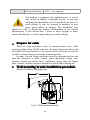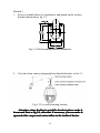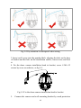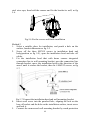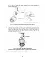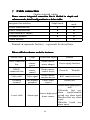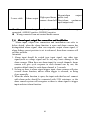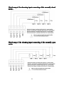
1
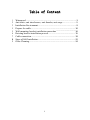
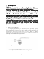
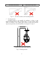
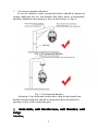
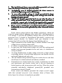
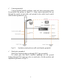
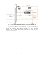
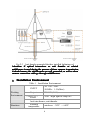
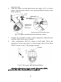
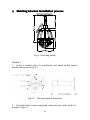
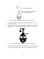
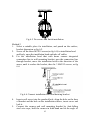
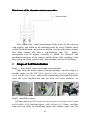
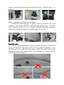
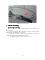
IR High Speed Dome Camera
Installation Manual
Read the user manual carefully before using this product
Table of Content
1
2
3
4
5
6
7
8
9
Waterproof......................................................................................... 3
Anti static, anti interference, anti thunder, anti surge.........................5
Installation Environment....................................................................9
Prepare for cable.............................................................................. 10
Wall mounting bracket installation procedure..................................10
Hoisting bracket installation process............................................... 15
Cable connection..............................................................................19
Steps of Self Installation.................................................................. 22
Glass Cleaning................................................................................. 24
ii
1
Waterproof
Attention
Attention:
1. It
It’’s recommended to use wall mounting bracket which arm
bracket is upward in certain angle for outdoor installation.
2. It
It’’s not allowed to use hoisting bracket and horizontal wall
bracket for outdoor installation, which will cause water inflow to
camera.
3. For User self-selected brackets, it
it’’s recommended to use those
with internal thread connector, it should also ensure the waterproof
performance of the brackets. If use external thread bracket for user
self-selected bracket, it should ensure the waterproof performance
of switching components that connect bracket and camera.
4. When install the camera, thread connector should be bound with
PTFE tape, also it should ensure the thread is sealed. In rainy and
moist area, it
it’’s suggested to apply waterproof paint in seaming
places after installation.
�
Wall-mounting Bracket
For outdoor installation,, it should use wall mounting bracket
which arm bracket is upward in certain angle, which can enable the
camera not so easy to have water inflow. As below figure: for outdoor
installation, wall-mounting bracket can be used cooperatively with hug
pillar type bracket and corner type bracket.
Fig 1-1 suit for outdoor wall mounting bracket
3
Horizontal arm bracket
Arm bracket slope down
Fig 1-2 not suit for outdoor wall mounting bracket
�
Hoisting bracket
Hoisting bracket is not suitable for outdoors, as there is gap
between hoisting bracket and fix hanger plate, it is easy to have water
inflow in outdoors, even if apply glass cement or bind with electrical
tape can not perfectly solve the problem of waterproof. As fig 1-3.
Fig 1-3 Hoisting bracket
4
�
Use client customized bracket
If use for outdoors, client customized bracket should be upward in
certain angle(can not use arm bracket that slope down or horizontal),
and there should not be opening or flaw on the bracket, as fig1-4.
Fig 1-4 Customized Bracket
Fig 1-5 Customized Bracket
Attention: if use horizontal arm bracket, then the horizontal arm
bracket and the stand pole should be integrated, there should not be
opening or flaw in the connecting part.
2 Anti static, anti interference, anti thunder, anti
surge
Attention
Attention:
5
1. The installation of dome camera should be grounded, or it may
cause the damage of electronic pieces by static
2.
In lightning area, it should grounded the dome camera to
release the high energy and avoid damage.
3. In area with unstable voltage, it should grounded the dome
camera to release the high energy such as surge and avoid the
burning of camera power.
4. Install anti thunder grounded lead can not take the place of
safety grounded lead. If use bad grounded stand pole such as
wood pole, cement pole, it should also install safety grounded
lead to ensure the camera or stand pole will not cause incident.
5. Dome camera anti thunder grounded lead should be grounded
individually, it can not be grounded by other electronic devices
near by.
Dome camera adopts built-in anti thunder technology, which can
resist the instant indirect lightning strike under 4KV when grounded is
well enough. To prevent the lightning damage that exceed the built-in
protection level, it should be implemented individually, construct anti
thunder project directly, for outdoor work, pay attention to the
construction skill can reduce the damage from lightning and etc.
1. Signal transmission line should keep 50 meters distance from high
voltage devices or high voltage cable.
2. It’s better to routing under eave for outdoor wiring.
3. In open area, the wiring should adopts seal steel tube underground
method, and one-point grounded to the steel tube, it’s forbidden to
wiring overhead.
4. In strong thunderstorm or high voltage area(such as high voltage
converting station), it should adopt high power anti thunder devices
and install lightning rod and so on.
4. The anti thunder and grounded design for outdoor device and lines
should suits for related national and industry standard.
6. Grounded device should satisfy the system requirements for both
anti interference and electric safety, and it can not shorting or
hybrid junction with strong power grid zero line. When the system
grounded individually, impedance ground≤4Ω, grounded wire
sectional area should ≥25mm2.
Dome camera anti thunder grounded line adopts several copper
cable that sectional area≥4mm2 (wire diameter about ≥2.3mm), take
below figure for reference to implement grounded.
6
�
Cement grounded:
Cement method should configure with steel tube protection jacket
for grounded line poling, as figure 2-1, dome camera grounded line go
through the inside of steel tube and ground to the earth, local control
center normal grounded is ok.
Fig 2-1
Insulation stand pole(or wall) anti thunder grounded
�
Metal pole grounded:
Metal pole method adopts go through PVC pipe grounded.
For metal pole that hasn’t installed lightning rod, the ground
lead(go through PVC pipe) get close to metal pole, fixt the position and
implement grounded, as fig 2-2.
7
Fig 2-2 Anti thunder grounded that hasn’t installed lightning rod
For metal pole that has installed lightning rod, the ground lead goes
through the inside of metal pole(go through PVC pipe) and then
grounded, and PVC pipe should keep enough distance from the inwall
of metal pole, as fig 2-3.
8
Fig 2-3 Anti thunder grounded that has installed lightning rod
Attention: if optical transceiver or anti thunder or related
middleware is used during the process of dome camera transmission,
it should ensure the middlewares are well grounded, as well as when
camera connection cable go through middlewares.
3
Installation Environment
Working
Environment
Table 1 Installation Environment
AC 100~240V
INPUT
50/60Hz 1.5A(Max)
Output
DC 15V(4.0A)
(OUTPUT)
24W(high light IR lamp on)
Power
Anti interference, anti thunder
Humiture
Working
temperature
outdoors:-30ºC ~+60ºC
9
Relative humidity
≤90%(no condense)
This product is equipped with standard power, it can be
only install in indoors, watertight caisson, or put into
bracket(in the installation box), it should fix the power to
avoid gliding. It can’t be exposed in outdoors or may
cause water inflow or burnout. The installation area
should be solid, it should not broken, delaminating or has related
phenomenon, it also should bear 5 times or above weight of dome
camera and bracket, to avoid image shaking or camera falling.
4
Prepare for cable
There are some resistances exist in common power lines, when
transmit voltage, there will be some lost, the longer the power line is and
the smaller the wire diameter is, the heavier lost it will cause. In order to
avoid the voltage shortage caused by transmission line.
In order to avoid voltage shortage caused by transmission line and
then the abnormal of dome camera, when implement wiring, wire
diameter should not smaller then 1 millimetre, power lines not longer
than 2 meters, and the connector should be welded with soldering tin.
5
Wall mounting bracket installation procedure
Attention: bracket is optional part
Fig 5-1 Wall mounting sketch
10
Method 1
1. Select a suitable place for installation, and punch on the surface,
bracket dimension as fig 5-2.
Fig 5-2 Wall mounting bracket dimension
2.
Pass the dome camera integrated line through bracket, as fig 5-3
Fig 5-3 Fix wall mounting bracket
Attention: when the line is out of the bracket, please make it
downward first as fig 5-4, after that if necessary, you can make it
upwards, this can prevent water inflow to the inside of device.
11
Fig 5-4 Pay attention to waterproof when wiring
3. Insert swell screw into the punched hole, aligning the hole on the base
of bracket and the hole on the installation surface, insert screw and lock
it.
4. Fix the dome camera installation head to bracket, screw 4 M6×12
screws by cross screwdriver, as fig 5-5.
Fig 5-5 Fix the dome camera installation head to bracket
5.
Connect the camera and wall mounting bracket by crash protection
12
steel wire rope, then hold the camera and fix the bracket to wall, as fig
5-6.
Fig 5-6 Fix the screws and finish installation
Method 2
1. Select a suitable place for installation, and punch a hole on the
surface, bracket dimension as fig 5-2.
2. Screw off the three M5X19 screws in installation head and
body(position as fig 5-9), open the installation head and take off
cables.
3. Fix the installation head that with dome camera integrated
connection line to wall mounting bracket, pass the connection line
through bracket, move the installation head in the direction of the
arrow, until it reaches the bracket, then fix 4 M6X12 screws, as fig
5-7.
4.
5.
Fig 5-7 Connect the installation head and wall mounting bracket
Insert swell screw into the punched hole, aligning the hole on the
base of bracket and the hole on the installation surface, insert screw
and lock it.
Connect the camera and wall mounting bracket by crash protection
13
6.
steel wire rope.
Hold the camera in both hand and in the angle of 45° as below
figure, align the dome camera cover rotate pendant to bracket rotate
hook, as fig 5-8.
Fig 5-8 Connect installation head and dome camera
7.
8.
Connect the terminals of dome camera integrated connection line
with the socket on the top of camera.
After confirmation, hold the camera in both hand, follow the
direction of arrow and rotate to vertical angle, then fix the three
M5X19 screws as fig 5-9 by hexagon wrench.
Fig 5-9 Fix screws and finish installation
Attention: glass is easy to get scratch, please take off the
protective film after the installation is completed.
14
6
Hoisting bracket installation process
Fig 6-1 Hoisting sketch
Method 1
1. Select a suitable place for installation, and punch on the surface,
bracket dimension as fig 6-2.
Fig 6-2 Hoisting bracket dimension
2. Insert the dome camera integrated connection line to the inside of
bracket, as fig 6-3.
15
Fig 6-3 Connect installation head and hoisting bracket
3.
4.
Fix the dome camera installation head to bracket, screw 3 M6×12
screws , as fig 6-6.
Insert swell screw into the punched hole, align the hole on the base
of bracket and the hole on the installation surface, insert screw and
lock it.
Fig 6-4 Connect IR installation head and dome camera
5.
Connect the camera and wall mounting bracket by crash protection
steel wire rope, then hold the camera and fix the bracket to wall.
16
Fig 6-5 Fix screws and finish installation
Method 2
1. Select a suitable place for installation, and punch on the surface,
bracket dimension as fig 6-2.
2. Screw off the three M5X19 screws(as fig 6-8) in installation head
and body, open the installation head and take off cables.
3. Fix the installation head that with dome camera integrated
connection line to wall mounting bracket, pass the connection line
through bracket, move the installation head in the direction of the
arrow, until it reaches the bracket, then fix 3 M6X12 screws, as fig
6-6.
Fig 6-6 Connect installation head and hoisting bracket
4.
5.
Insert swell screw into the punched hole, align the hole on the base
of bracket and the hole on the installation surface, insert screw and
lock it.
Connect the camera and wall mounting bracket by Anti-falling
steel wire rope, hold the camera in both hand and in the angle of
17
45° as fig 6-7, align the dome camera cover rotate pendant to
bracket rotate hook.
Fig 6-7 Connect IR installation head and dome camera
6.
Connect the terminals of dome camera integrated connection line
with the socket on the top of camera. After confirmation, hold the
camera in both hand, follow the direction of arrow and rotate to
vertical angle, then fix the three M5X19 screws as fig 5-9 by
hexagon wrench, as fig 6-8.
Fig 6-8 Fix screws and finish installation
Attention: there should not be holes or craze in the suspension
bracket connecting pole, to avoid water inflow.
18
7
Cable connection
Camera external wiring
Dome camera integrated connection line is divided to simple and
enhance mode, detail configuration is as below table:
Enhance
Integrated line interface
Simple mode
mode
Power connection line
●
●
RS485 connection line
Video cable(BNC output)
Grounded terminal
Alarm interface
●
●
●
—
●
●
●
●
Remark: ● represents for have, – represents for do not have
Below will take enhance mode for instance:
electric cable
Power connection
line
RS485
connection line
Usage
Dome
camera
power
Dome
camera
control
Video cable
Video signal
Grounded
terminal
Anti thunder
grounded
5 cores cable
Connection object
Remark
Dome camerapower adapter
Power supply interface
Dome cameracontrol device
Green(A); White(B)
Dome cameramonitor device
Earth- dome
camera
BNC connection head
Brown line
Black(alarm input public
end)
Yellow(the first way
alarm
input)Green(the
Sensor- high speed
Alarm input
second way alarm input)
dome camera
Blue(the third way alarm
input)
White(the fourth way
alarm input)
19
2 cores cable
Brown(alarm
output
High speed dome public end)
Alarm output
camera- alarm bell Gray(alarm continuous
open output end)
◆ The positive and negative polarity of RS485 can not be wrong
connected, A:RS485 positive, B:RS485 negative
◆ Wrong connected can not control dome camera
7.0 Alarm input, output line connection and installation
Alarm input, output line connection and installation can refer to
below sketch, when the alarm function is open and dome camera has
distinguished alarm signal, then can response output alarm signal; if
alarm linkage preset position is set in advanced, then dome camera will
call this position.
Attention:
1. Alarm input should be switch type input signal, any other type
signal(such as voltage signal and so on) may cause damage to the
dome camera. When there are alarm input for several channels, dome
camera will give cycle response to each channel one by one, the
monitor default time for each alarm channel is 3 seconds.
2. So long as there is alarm signal trigger input, dome camera will prior
execute alarm function, unless alarm trigger is released, or being
close manually.
3. When the alarm function is open, the input ends that haven’t connect
with alarm probe should be connected with 2.2K resistance, or the
dome camera system will recognize as there is alarm signal to trigger
input and start alarm function.
20
Sketch map of the alarming input connecting of the normally closed
probe
probe:
Sketch map of the alarming input connecting of the normally open
probe
21
Sketch map of the alarming output connecting:
After connecting,check and arrange all the wires, tie the wires up
with girding, and fasten on the installing panel by screw. Double check
it after the installation, and set up an electric circuit on the dome camera.
The dome camera will take a self-checking, turn 360
degree
horizontally and 90 degree vertically to check the electrical and
mechanical structure of the camera and the dome After resetting to the
basic point, the dome camera stops which means a good self-checking.
8
Steps of Self Installation
Step1 :Take off the camera front end cover modules
Take away the dome camera from the package, turn the chip to a
suitable angle, use the H2.5 Hex wrench in the accessory package to
screw out the four screws,pull out the connecting wires installed on the
front end cover modules,and take off front end cover modules. As
follows:
Step2:install the camera
Put the camera parallel under the install panel until the camera aims
at the middle of the front end cover, with a distance of 1-2mm,and then
align the four holes on installation panel and camera, make sure the
22
image is in right direction, and then lock the screw.(M2X4 screw)As
follows:
Step3:install the front end cover modules
Install the connecting wire to proper place in the front end cover
modules,and connect the FPC cable with the camera base, lock the
screw between front end cover modules and the chip after checking,
finally turn the dome camera to vertical angle. As follows:
Special notice:
The seal ring should keep smooth with the interface of front end
cover, not hunched. The edge of the seal ring should completely cover
the front end cover, and the screw must be locked to make sure a good
sealing up and avoid leaking which may damage the camera and the
electric circuit.As follows:
23
Hunched and not properly enveloped seal ring
Totally installed seal ring
9
Glass Cleaning
Notice of glass cleaning:
1. Clean the glass regularly could ensure the clear image of the
dome camera.
2. Avoid touching the glass directly by hand or skin which may
probably make bad influence to the image.
3. Please use a soft dry cloth or other substitutes to clean the
surface.(hard object may cause indistinct image)
4. Using glass cleaner to remove any stubborn dirt.
24