1
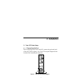
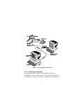
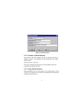
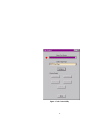
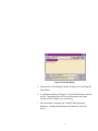
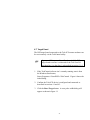
Trek-ICE Universal Emulator
Hardware and Software
Installation Guide
2000
White Mountain DSP
Notice
Analog Devices, Inc. reserves the right to make changes to or to discontinue
any product or service identified in this publication without notice.
Analog Devices assumes no liability for Analog Devices applications
assistance, customer product design, customer software performance, or
infringement of patents or services described herein. In addition, Analog
Devices shall not be held liable for special, collateral, incidental or
consequential damages in connection with or arising out of the furnishing,
performance, or use of this product.
Analog Devices products are not intended for use in life-support
applications, devices, or systems. Use of an Analog Devices product in such
applications without the written consent of the appropriate Analog Devices
officer is prohibited.
Users are restricted from copying, modifying, distributing, reverse
engineering and reverse assembling or reverse compiling the Trek-ICE
operational software (one copy may be made for back-up purposes only).
No part of this document may be reproduced in any form without
permission.
Trademarks are property of their respective holders.
Limited Warranty
The Trek-ICE hardware is warranted against defects in materials and
workmanship for a period of one year from the date of purchase from Analog
Devices or from an authorized dealer.
Copyright © 1999-2000, Analog Devices, Inc. All rights reserved.
Revision 1.1, February 2000
MANTREKICE H/W
i
Contents
1. INTRODUCTION................................................................................... 1
2. REQUIREMENTS.................................................................................. 2
3. INSTALLATION .................................................................................... 3
3.1 TREK-ICE CABLE SETUP ..........................................................................................3
3.1.1 CONNECTING THE POD....................................................................................3
3.1.2 CONNECTING TO A NETWORK ........................................................................5
3.1.3 SERIAL PORT ......................................................................................................6
3.1.4 USER I/O PORT ...................................................................................................6
3.1.5 RESET PUSHBUTTON ........................................................................................7
3.1.6 POWER SWITCH .................................................................................................7
3.2 TREK-ICE NETWORK CONFIGURATION ...............................................................7
3.2.1 ADDING A DHCP SERVER ENTRY....................................................................8
3.2.2 IP ADDRESS TO NAME MAPPING ..................................................................10
3.2.3 USING A DEFAULT GATEWAY........................................................................10
3.3 DIAGNOSING NETWORK PROBLEMS..................................................................11
3.3.1 PING ....................................................................................................... 11
4. TREK CONTROL SOFTWARE......................................................... 12
4.1 INSTALL THE TREK SOFTWARE...........................................................................13
4.2 CONFIGURING TREK NETWORK ADDRESSES ..................................................13
4.3 TARGET TYPE SELECTION ....................................................................................17
4.4 TREK CONNECTION ................................................................................................17
ii
4.5 TREK SOFTWARE DOWNLOAD ............................................................................19
4.6 TREK REBOOT..........................................................................................................22
4.7 TARGET RESET ........................................................................................................23
4.8 ICETEST UTILITY.....................................................................................................24
5. CONFIGURING THE SOFTWARE .................................................. 26
5.1 DOWNLOAD THE TARGET SOFTWARE TO TREK-ICE......................................26
5.2 CREATING THE VISUALDSP DEBUG APP SESSION..........................................27
6. SUPPORT ............................................................................................. 29
6.1 TECHNICAL SUPPORT ............................................................................................29
6.2 QUALITY ASSURANCE ...........................................................................................29
7. REFERENCES ...................................................................................... 30
iii
List of Figures
FIGURE 1. TREK-ICE REAR PANEL DIAGRAM..................................................................3
FIGURE 2. TREK-ICE NETWORK CONNECTION ...............................................................5
FIGURE 3. USER I/O PORT RESET PIN LOCATIONS ........................................................7
FIGURE 4. DHCP SCOPE PROPERTIES ...............................................................................9
FIGURE 5. CLIENT RESERVATION ...................................................................................10
FIGURE 6. TREK CONTROL UTILITY ...............................................................................14
FIGURE 7. CONFIGURATION DIALOG .............................................................................15
FIGURE 8. ADD DIALOG .....................................................................................................16
FIGURE 9. DEVICE CONNECT ...........................................................................................19
FIGURE 10. FIND FILE DIALOG .........................................................................................21
FIGURE 11. RESET PULSE WIDTH DIALOG ....................................................................24
FIGURE 12. ICETEST UTILITY ...........................................................................................25
FIGURE 13. NEW SESSION SELECTION...........................................................................28
iv
1. Introduction
The White Mountain DSP Trek-ICE Universal Emulator system
provides state-of-the-art TCP/IP network based emulation and support
for Analog Devices JTAG DSP’s. The key features of the Trek-ICE
system are as follows:
s Remote network debugger support
s Rugged high-speed 2.5V or 3V/5V JTAG emulation pod for
Analog Devices DSPs
s 10/100BASE-T network interface
1
2. Requirements
The minimum PC host requirements for the Trek-ICE are as follows:
s Pentium 166 MHz or better
s Minimum of 32 megabytes of RAM memory
s Windows 95b, 98 or Windows NT 4.0 SP3 operating system
s Windows NT 4.0 SP3 DHCP server to supply an IP address
2
3. Installation
3.1 Trek-ICE Cable Setup
Connecting the Pod
Prior to applying power to the Trek-ICE, connect the pod to the back
of the unit. Refer to figure 1, the Trek-ICE rear panel diagram for the
location of the emulator pod connector.
3.1.1
Figure 1. Trek-ICE Rear Panel Diagram
3
+
Important! Connect/disconnect the remote pod to/from
the emulator unit only when the Trek-ICE power is turned
off. Failure to follow this precaution may result in damage
to the pod or unit.
The 14-pin pod target connector is permanently keyed to avoid damage
caused by accidentally reversing the header. If your target system does
not have the proper pin removed, you must remove the pin before the
pod can be connected to the target system. This is pin 3 on the 14-pin
JTAG connector.
4
Reset Line
Figure 2. Trek-ICE Network Connection
3.1.2 Connecting to a Network
Connect the Trek-ICE to an 802.3 Ethernet/IEEE network via a
10/100BASE-T cable. Refer to figure1 for the location of the Ethernet
10/100BASE-T connector. When power is applied to the emulator the
5
LINK LED on the rear panel should illuminate, indicating a valid
physical network connection.
3.1.3 Serial Port
The 9-pin D-Sub Serial Port connector on the rear panel is used only
for factory diagnostics and should not require connection for normal
operation.
3.1.4 User I/O Port
The Trek 15-pin User I/O port connector (figure 3) can be used to reset
the DSP target board. A wire must be installed from the Trek User I/O
port Data line 0 or 1 to the DSP target board if a remote reset is
desired. Data line 0 on the connector will initially be set to a logic
high on startup. Data line 1 on the connector will initially be set to a
logic low on startup. Either data line 0 or 1 may be connected to the
reset line on the target DSP board. If the target DSP board requires a
logic low to reset the board then data line 0 should be used. If a logic
high reset is required then data line 1 should be used. These data lines
can be toggled for a given duration via software control on the client
PC. This procedure is discussed in section 4.7.
The output signals are open collector signals pulled up to 5V with a 1K
resistor and can sink 15mA.
6
Figure 3. User I/O Port Reset Pin Locations
3.1.5 RESET Pushbutton
The RESET pushbutton on the rear panel of Trek-ICE will perform
power-on reset when pressed.
3.1.6 POWER Switch
The POWER switch is located on the rear panel. The switch should be
in the off position (O) when plugging the power cord into an outlet.
When the POWER switch is in the on position ( I ) the green LED on
the front panel will illuminate immediately and the red LED on the
front panel will illuminate when the Trek-ICE is ready to receive
commands, approximately 30 seconds to 1 minute from power on.
3.2 Trek-ICE Network Configuration
The Trek-ICE must be connected to a network and a target for proper
operation. The Trek-ICE requires an IP address, subnet mask and a
default gateway to communicate on the network. The default gateway
is optional and is only needed in the case where the Trek-ICE is not on
7
the same network segment as the client PC. This information will be
provided by a network server, each time the Trek-ICE goes through a
power-on or reset cycle. The required mechanism for supplying this
information to the Trek-ICE is DHCP via the Windows NT 4.0 server.
See figure 2, the Trek-ICE Network Connection for details.
When the Trek-ICE is powered on or reset, the boot loader performs
all of the necessary system initialization, acquires its IP and Gateway
addresses via an NT DHCP server, and then waits for the host
application software (VisualDSP® debugger application or
TrekControl) to connect via Ethernet.
3.2.1 Adding a DHCP Server Entry
There are many ways to configure a DHCP server for use with the
Trek-ICE. This section explains the process of how the Trek-ICE
requests its IP address, and contains important information on how to
setup an entry in the DHCP table.
The underlying mechanism for the Trek-ICE emulator to acquire its IP
address is through a DHCP request. Make sure that your System
Administrator has installed the DHCP server on your Windows NT 4.0
server machine. In order for the DHCP server to respond to the TrekICE’s request, your System Administrator has to make a client
reservation and give a permanent lease to the Trek-ICE via the
appropriate DHCP entries. This is done by creating a DHCP scope as
shown in figure 4. Enter the appropriate address range, subnet mask,
and any excluded IP addresses. Make it a permanent lease by checking
the unlimited box for lease duration.
8
Next create a client reservation. The minimum requirement for the
client entry is the Unique Identifier (MAC address) of the Trek-ICE,
which is its serial number (example: 08001708a1b1), and the client
name as shown in figure 5. Your System Administrator should also
add any other DHCP properties specific to your network.
It is strongly recommended that a System Administrator, familiar with
your network, setup and configure the DHCP server for the Trek-ICE.
Figure 4. DHCP Scope Properties
9
Figure 5. Client Reservation
3.2.2 IP Address to Name Mapping
Using DNS or some other method you can also map the Trek-ICE IP
address to a name. You could have an entry in the “hosts” file which
looks like this:
198.246.200.100 TREK-ICE
This name could then be used in place of the IP address when you
communicate with the Trek-ICE.
3.2.3 Using a Default Gateway
When using DHCP you have the option to set a default gateway for the
Trek-ICE. This allows your Trek-ICE to communicate across network
segments (through routers).
10
3.3 Diagnosing Network Problems
There are several OS commands provided for gaining insight into the
state of your network. One of these commands is ping, which it is
described in the next section.
There are also four LED’s on the rear panel, which indicate the
network status of the Trek-ICE:
•
•
•
•
LINK: there is a valid physical connection to an Ethernet network
RECEIVE: packets are present on the network
TRANSMIT: the Trek-ICE is transmitting packets
COLLISION: packet collisions on the network are being detected
3.3.1 Ping
Ping will tell you if your Trek-ICE has basic network communication
capabilities. An example would be:
C:>ping 198.246.200.100
or
C:>ping Trek-ICE
11
4. TrekControl Software
The TrekControl.exe program is a software utility that communicates
with the Trek-ICE device via ethernet. TrekControl is used to
configure network IP addresses of the Trek-ICE devices, download
software updates, reboot the Trek-ICE device, reset the user’s DSP
target board and run the IceTest utility. The following sections
describe each of the TrekControl functions.
This manual assumes the TrekControl application is used with
VisualDSP® software. If TrekControl is provided by other third party
vendors, the user should refer to the vendor’s documentation.
12
4.1 Install the Trek-ICE Software
1.
Insert the Trek-ICE installation CD and run the Setup.exe program
to install the Trek-ICE software.
The Trek Software is installed into the VisualDSP/Trek-ICE
directory.
4.2 Configuring Trek Network Addresses
This step is necessary to establish communication with the Trek-ICE
device.
+
Important! The Trek-ICE device DHCP network address
must be configured as described in section 3.2 before
proceeding.
1. Confirm the Trek-ICE device is turned on and operating properly
as described in sections 3.2 and 3.3.1.
2. Start the TrekControl software from the Windows Start button,
Start⇒Programs⇒VisualDSP⇒TrekControl. Figure 6 shows the
initial dialog.
13
Figure 6. Trek Control Utility
14
3. Click the Configure button. The Configure dialog will appear.
Initially no Trek devices are configured, so the Configured Devices
list is empty. See figure 7.
4. Click the Add button to add a new Trek configuration. The Add
dialog will appear as shown in figure 8.
Figure 7. Configuration Dialog
15
Figure 8. Add Dialog
5. Enter the IP Address or Network Name of the Trek-ICE device that
was established in section 3.2.2.
6. Enter any desired text as the description. The location of the Trek
device would be appropriate.
7. Click the OK button after the IP Address and description has been
entered.
8. The Configured devices text box now contains the Trek-ICE
device configuration. Repeat steps 4-7 to add another device or
click OK to save the configuration data.
16
4.3 Target Type Selection
Before the VisualDSP software is used with Trek-ICE a target type
must be selected. The Trek-ICE installation software will insert the
proper target type into the target type pull down list.
1. If the TrekControl software isn’t currently running, start it from the
Windows start button,
Start⇒Programs⇒VisualDSP⇒TrekControl. Figure 6 shows the
initial dialog.
2. Click on the Target Type pull down list (see figure 6) and select the
appropriate target type.
The selected target type will be available after Connect and Reboot
actions are taken as described in the following sections.
4.4 Trek Connection
Before any of the Trek-ICE utilities can be used, a network connection
to the device must be established.
1. Confirm the Trek-ICE device is turned on and operating properly
as described in sections 3.2 and 3.3.1.
2. If the TrekControl isn’t currently running, start it from the
Windows start button,
Start⇒Programs⇒VisualDSP⇒TrekControl. Figure 6 shows the
initial dialog.
17
3. The Select Trek-ICE Device drop down list should contain at least
one configured device. If not, follow the instructions in section
4.1.
4. Select the desired device from the Select Trek-ICE Device drop
down list. The red circle to the left of the device selection
indicates that the device is currently not connected.
5. Click the Connect button. See figure 9. If the connection is
successful then a green circle will appear next to the device
selection and the Download, Reboot Reset and IceTest buttons will
become active.
+
Note! If an error message appears then the Trek-ICE
device is either not configured correctly, not turned on or
is malfunctioning. Review all previous sections for
correct configuration.
18
Figure 9. Device Connect
4.5 Trek-ICE Software Download
Occasionally Trek-ICE software updates may be necessary. Analog
Devices or other qualified third party companies will provide these
updates.
19
+
Important! Only software updates from Analog Devices
or qualified third party companies should be downloaded
to the Trek-ICE Device. Downloading of other software
to the Trek-ICE device may cause the device to stop
functioning.
1. Confirm the Trek-ICE device is turned on and operating properly
as described in sections 3.2 and 3.3.1.
2. If the TrekControl software isn’t currently running, start if from the
Windows Start button,
Start⇒Programs⇒VisualDSP⇒TrekControl. Figure 6 shows the
initial dialog.
3. Confirm the Trek-ICE device is configured and connected as
described in sections 4.1 and 4.3.
4. Select the Download button. The File Select dialog will be
displayed as in figure 10.
20
Figure 10. Find File Dialog
5. Select the file to download by double clicking on it or clicking the
Open button.
6. A confirmation dialog will appear. Press the Yes button to transfer
the file. Depending on the file size, the download could take
anywhere from seconds to several minutes.
7.
After download is complete the Trek-ICE Reboot dialog is
displayed. Clicking the Yes button will reboot the Trek-ICE
device.
21
4.6 Trek Reboot
The TrekControl utility can be used to remotely reboot the Trek-ICE
device.
+
Important! This feature may fail if the Trek-ICE device is
no longer responding to network commands.
1. Confirm the Trek-ICE device is turned on and operating properly
as described in sections 3.2 and 3.3.1.
2. If the TrekControl software isn’t currently running, start it from the
Windows Start button,
Start⇒Programs⇒VisualDSP⇒TrekControl. Figure 6 shows the
initial dialog.
3. Confirm the Trek-ICE device is configured and connected as
described in sections 4.1 through 4.3.
4. Click the Reboot Trek button. A confirmation dialog will appear.
Click Yes to reboot the Trek device.
5. Wait 1 minute for the device to reboot before attempting a
connection. Click OK. Then Click Connect.
22
4.7 Target Reset
The DSP target board connected to the Trek-ICE remote emulator can
be reset remotely via the TrekControl utility.
+
Important! This reset utility will only work if the DSP
target board reset line is connected to the Trek User I/O
port data line 0 or data line 1 as described in section 3.1.4.
1. If the TrekControl software isn’t currently running, start it from
the Windows Start button,
Start⇒Programs⇒VisualDSP⇒TrekControl. Figure 6 shows the
initial dialog.
2. Confirm the Trek-ICE device is configured and connected as
described in sections 4.1 and 4.3.
3. Click the Reset Target button. A reset pulse width dialog will
appear as shown in figure 11.
23
Figure 11. Reset Pulse Width Dialog
4. Enter the desired reset pulse width (milliseconds).
5. Click the Send Pulse button to reset the DSP target board.
4.8 IceTest Utility
The IceTest utility is used to verify and test a target JTAG connection.
1. If the TrekControl software isn’t currently running, start it from the
Windows Start button,
Start⇒Programs⇒VisualDSP⇒TrekControl.
2. Confirm the Trek-ICE device is configured and connected as
described in sections 4.1 through 4.3.
24
3. Confirm a target DSP board is connected to the Trek-ICE device.
4. Click the IceTest button. The IceTest dialog will appear as shown
in figure 11.
5. Click the Start button to run the IceTest utility. If Continuous scan
is selected the IceTest will run until the Stop button is pressed.
Figure 12. IceTest Utility
25
5. Configuring the Software
5.1 Download the Target Software to Trek-ICE
Initially the Trek-ICE device doesn’t have any target specific software
loaded. The user must perform a one-time software download to the
Trek-ICE device. Review section 4.5 for details on downloading files
to the Trek-ICE device.
1. Verify the Trek-ICE device is configured and powered on.
2. Use the TrekControl utility to select the desired remote device and
target type. See section 4.3. Click the Connect button to establish
a connection to the Trek-ICE device.
3. Click the Download button.
4. Navigate to the Trek-ICE directory (this directory was created by
the Trek install utility).
5. Select and download “SharcSocStubCE.exe”
6. Repeat steps 3,4, and 5 for the file “WmSharcIceCE.dll”
26
Note: The file names “SharcSocStubCE.exe” and
“WmSharcICECE.dll” are included with the ADSP-21xxx
SHARC® installation. These file names will change with other
installations.
7. Reboot the Trek-ICE device
5.2 Creating the VisualDSP® Debugger Application Session
This section applies only for a VisualDSP® installation.
+
Important! The Trek-ICE device must be installed and
powered on and configured (as described in sections 3.2,
3.3.1 and 4.1) before proceeding with this section.
8. Verify the Trek-ICE device is configured and powered on.
9. Use the TrekControl utility to select the desired remote device and
target type. See section 4.3. Click the Connect button to verify
the trek device is operating.
10. Run the IceCfg utility to setup DSP target types,
Start⇒Programs⇒VisualDSP⇒JTAG ICE Configurator. See the
VisualDSP emulation user’s manual for more information. Note:
The Base Address entry isn’t required for Trek-ICE.
11. Start the VisualDSP® debugger application,
Start⇒Programs⇒VisualDSP⇒Debugger
or from the Windows start menu.
27
12. Select Session from the menu bar. Then choose New Session from
the list.
13. Under the Debug Target pull down list select ADSP-21xxx Trek
JTAG Emulator. See figure 13.
14. Under Platform choose the desired DSP target type connected to
the Trek-ICE device.
15. Click OK. The VisualDSP® debugger application is now ready to
use.
+
Note! If an error message appears, the Trek-ICE device is
not installed correctly. Verify all previous steps.
Figure 13. New Session Selection
28
6. Support
6.1 Technical Support
We fully support all our products under the White Mountain DSP
Rock Solid Support Program. For technical support within North
America, call (603) 883-2430 Monday through Friday during normal
business hours or via e-mail at [email protected]. For technical
support outside of North America, call your local White Mountain
DSP distributor. For direct support of the Analog Devices DSP’s, call
the Analog Devices’ DSP Applications Engineering group at (781)
461-3672.
6.2 Quality Assurance
White Mountain DSP is committed to providing quality products and
services. In efforts to continually provide this quality, please contact
our Quality Assurance Department directly if you have any concerns at
(603) 883-2430 Monday-Friday during normal business hours or via email at [email protected]. Our Quality Assurance Manager will
listen to your concerns and provide a timely and effective solution.
29
7. References
Internetworking with TCP/IP Vol. I, 3rd Edition, Douglas Comer
TCP/IP Illustrated Vol. I, W. Richard Stevens
30