1
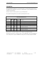
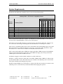
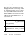
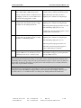
STS Product Family
User Manual
April 28, 2015
Revision A01
Abstract
The LAVA STS Product Family allows select Samsung Tablets to be charged while interacting with USB
accessories, and enable a tablet-based kiosk or enclosure to support a variety of applications requiring:
OTG USB Host operation with simultaneous tablet charging
Interaction with USB accessories while charging the tablet
Wired network operation (10/100 Ethernet)
Power over Ethernet (PoE)
The STS Product Family work with out-of-the-box (unrooted) Samsung tablets, and are ideal for
commercial and OEM applications.
This document describes the ports, indicators, and buttons on the STS** Products. This document describes
how to test and setup a STS** device. The term STS** is used in this document to refer to a member of the
STS Product Family.
Contents
Introduction.....................................................................................................................2
System Requirements ......................................................................................................3
Hardware Testing and Setup............................................................................................4
Hardware Test - Out of the box unit.............................................................................4
Hardware Setup - STS (formerly TL002c) ...................................................................6
Hardware Setup - STS-3U ...........................................................................................7
Hardware Setup - STS-E, STS-2UE, and STS-2UE+ ...................................................8
Hardware Setup - STS-PE, STS-P2UE, and STS-P2UE+.............................................9
Special Instructions for the Samsung Tab 4 ...............................................................10
Tablet Charging (SimulCharge versus Charge-Only Mode) ...........................................11
Ports, Indicators, and Buttons ........................................................................................12
“Mode Select” Button and Indicators.........................................................................12
“Micro-B USB To Tablet”.........................................................................................12
“Micro-B USB 5V Power Input” ...............................................................................13
“Micro-B USB Aux 5V Input” ..................................................................................13
“USB-A” receptacles.................................................................................................13
“ETHERNET” Port and Indicators ............................................................................14
“PoE-ETHERNET” Port and Indicators.....................................................................15
“PoE power” Indicator...............................................................................................15
Power over Ethernet (PoE) ............................................................................................16
STS Module (formerly TL002c) ....................................................................................17
Dimensions ...................................................................................................................19
Technical Support .........................................................................................................20
History ..........................................................................................................................20
LAVA Computer MFG
STS Product Family User Manual – A01
Introduction
The LAVA STS Product Family allows select Samsung tablets to be charged while interacting with one or
more USB accessories. The STS** products allows a Samsung tablet to operate in OTG Host mode while
simultaneously being charged.
The STS** Products use features specific to a group of Samsung Tablets.
The compatible Samsung Tablets are noted in the System Requirements section.
STS Product Family Overview
USB
Ports
Ethernet
Adapter
STS
STS-3U
STS-E
STS-PE
STS-2UE
1
3
2
YES
YES
YES
Power
over
Ethernet
YES
-
STS-2UE+
2
YES
-
STS-P2UE
2
YES
YES
STS-P2UE+
2
YES
YES
Product
Description
1-port USB Adapter
3-port USB Hub
Ethernet Adapter
Ethernet Adapter with PoE
2-port USB Hub & Ethernet Adapter
2-port USB Hub & Ethernet Adapter,
for the Tab S and Tab Pro
2-port USB Hub & Ethernet Adapter with PoE
2-port USB Hub & Ethernet Adapter with PoE,
for the Tab S and Tab Pro
The term STS** is used in this document to refer to a member of the STS Product Family.
The LAVA product referred to as simply the “STS” is a 1-Port USB member of the LAVA STS Family of
devices. This product is a single board OEM device. This product was formerly designated the TL002c.
2 Vulcan St. Toronto, ON
Canada, M9W 1L2
Tel: +1 416 674-5942
Fax: +1 416 674-8262
www.lavalink.com
Toll Free (US & Canada): 800 241-5282
2 of 20
LAVA Computer MFG
STS Product Family User Manual – A01
System Requirements
The STS Product Family has compatible devices for the following Samsung tablets:
Samsung Tablet – STS Product Compatibility Matrix
STS-P2UE+
STS-P2UE
STS-2UE+
STS-2UE
Samsung Galaxy Tab 4 (8”)
Samsung Galaxy Tab 4 (10.1”)
Samsung Galaxy Tab S (8.4”)
Samsung Galaxy Tab S (10.5”)
Samsung Galaxy Tab Pro (10.1”)
Samsung Galaxy Tab Pro (12.2”)
Samsung Galaxy Note Pro (12.2”)
STS-PE
SM-T330
SM-T530
SM-T700
SM-T800
SM-T520
SM-T900
SM-P900
STS-E
Samsung Tablet
STS-3U
Tablet
Model
STS
LAVA STS Product
Please check the LAVA Web Site for updates to the STS Product Compatibility Matrix. As new tablets are
introduced, the Compatibility Matrix on the web site will be updated.
The features used by the STS** Products are not universal across the Samsung Tablet line. Variations may
also occur based on world region. Samsung tailors the tablet firmware to a world region or country.
STS** Power-over-Ethernet (PoE) models require a suitable Network Switch with PoE support. A non-PoE
Network Switch can use a PoE Power Injector for each port to operate with a STS** PoE device. A PoE
Power Injector is a common add-on available from many Network Switch vendors.
STS** models without PoE require a USB Power Supply with a Micro USB-B receptacle. The Wall/USB
Charger supplied with the tablet is an ideal choice. Any USB Power Supply can be used provided it has
sufficient power for the tablet and USB accessories.
A USB Power Supply is useful for initial verification of a STS** PoE device.
The STS** to Tablet connection is made with a custom Micro USB-B to Micro USB-B 39” (100 cm) cable
provided with the STS** device. This cable must not be extended, as the additional power loss in the wires
will result in unreliable tablet charging and operation.
The STS (formerly TL002c) is provided with an 8” (20 cm) cable. This cable should not be extended, as the
additional power loss in the wires may result in unreliable tablet charging and operation.
2 Vulcan St. Toronto, ON
Canada, M9W 1L2
Tel: +1 416 674-5942
Fax: +1 416 674-8262
www.lavalink.com
Toll Free (US & Canada): 800 241-5282
3 of 20
LAVA Computer MFG
STS Product Family User Manual – A01
Hardware Testing and Setup
Hardware Test - Out of the box unit
This section describes how to confirm a STS** device is functional and verifies interaction with a tablet.
The USB Hub feature of a STS** device requires no special setup within a tablet. STS** products with an
Ethernet adapter requires some tablet setup, which is covered in the Hardware Setup tables.
The steps for initial verification include the STS** PoE devices, which will temporarily use a USB Power
Supply. Devices using PoE must eventually configure a Network Switch for correct operation. Setting up a
Network Switch is vendor specific, therefore beyond the scope of this document. If you already have a
PoE capable switch, simply plug the STS** device into the switch via an Ethernet cable in place of the
“USB Power Supply” step.
The following steps assume the Tablet battery indicator icon is enabled. If the icon is not enabled, then the
Battery menu must be checked to determine the charging status. The Battery menu presents the option to
control the battery indicator icon.
Note: The test procedure assumes a STS (formerly TL002c) has no Type Jumper installed, and “pressing
the mode button” is equivalent to shorting the Mode pins. This board-only product is described in more
detail in a dedicated section of this document.
Note: For PoE capable devices; never apply PoE power at the same time as using the Aux 5V Input.
Out Of The Box Tests - Common to all products
Observations
The standard startup banner(s) and music are
reported. A new tablet requires the standard first
time setup required by manufacturer.
Step
1
Procedure
Turn on the tablet.
2
Ensure the USB Power Supply to be used is
active. If using a USB Power Supply that runs
off a wall outlet, plug the USB Power Supply
into the wall outlet. If using a battery pack, turn
the battery pack on.
3
Connect the USB Power Supply to the
5V Power Input of the STS** product.
The Charge-Only light (green) will flash on and
off for 2 seconds.
For a PoE device, connect the USB Power
Supply to the Aux 5V Input. This is assuming
that no power through the Ethernet port is
applied.
After the 2 seconds of flashing, the
SimulCharge light (yellow) is on solid, and the
Charge-Only light (green) is off.
If the indicator lights show no activity, verify
the power supply is plugged in and working.
2 Vulcan St. Toronto, ON
Canada, M9W 1L2
Tel: +1 416 674-5942
Fax: +1 416 674-8262
www.lavalink.com
Toll Free (US & Canada): 800 241-5282
4 of 20
LAVA Computer MFG
4
5
STS Product Family User Manual – A01
Connect the STS** to the tablet with the custom
Micro USB to Micro USB cable provided.
A tablet status message briefly appears to report
“USB connector connected” and issues a beep.
Always verify the connector orientation before
attempting to insert it to a device. Either end of
the cable can be plugged into to tablet.
The tablet battery icon will now show a
lightning bolt to indicate it is being charged.
Press the STS** Mode button for at least ¼
second, and no more than 4 seconds, to toggle
the STS** into the Charge-Only mode.
The tablet battery icon will now show a
lightning bolt to indicate it is being charged.
The Charge-Only light (green) will be on solid.
The SimulCharge light (yellow) is off.
A tablet status message briefly appears to report
“USB connector disconnected”.
6
Press the STS** Mode button again (at least ¼
seconds and no more than 4 seconds) to return
the STS** to SimulCharge Mode.
The tablet battery icon will now show a
lightning bolt to indicate it is being charged.
The SimulCharge light (yellow) is on.
The Charge-Only light (green) will be off.
The tablet status message briefly appears to
report “USB connector connected”.
7
If the STS** Product has a USB-A receptacle,
plug in a USB accessory. Possible accessories
include keyboard, mouse, or memory stick.
The tablet status reports the attached accessory.
The USB Power Supply is powering the tablet
and any USB accessories.
This completes the initial hardware testing of a new STS** device, and demonstrates the transitions from
SimulCharge Mode to Charge-Only mode. The specific hardware setup for a device can now be addressed.
For the STS and STS-3U, the hardware setup has just been demonstrated, however a dedicated hardware
setup section is present in this document.
If a PoE device was tested using the “Aux 5V Input”, it can now be tested with a Network Switch
configured for PoE. The USB Power Supply must be removed from the “Aux 5V Input”. The above test
procedure allows you to confirm the device is working before dealing with Network Switch issues.
2 Vulcan St. Toronto, ON
Canada, M9W 1L2
Tel: +1 416 674-5942
Fax: +1 416 674-8262
www.lavalink.com
Toll Free (US & Canada): 800 241-5282
5 of 20
LAVA Computer MFG
STS Product Family User Manual – A01
Hardware Setup - STS (formerly TL002c)
The LAVA product referred to as simply the “STS” is a 1-Port USB member of the LAVA STS Family of
devices. This product is a single board OEM device. This product was formerly designated the TL002c.
The STS has no required setup in the tablet. The tablet battery indicator icon can be useful to have enabled,
but is optional. The charging status of the tablet can always be checked in the tablet battery menu.
The module has no TYPE Jumper or MODE Jumper installed by default. Please see the dedicated STS
Module section for a description of the module jumpers.
Step
1
2
3
4
5
Hardware Setup – for the STS (formerly TL002c)
Observations
The standard startup banner(s) and music are
reported. A new tablet requires the standard first
time setup required by manufacturer.
Plug the USB Power Supply into a wall outlet.
If using a battery pack, turn the battery pack on.
Connect a USB Power Supply to the
The Charge-Only light (green) will flash on and
5V Power Input of the STS** product.
off for 2 seconds, after which the SimulCharge
light (yellow) is on and the Charge-Only light
(green) is off.
Connect the STS** to the tablet with the custom A tablet status message briefly appears to report
Micro USB to Micro USB cable provided.
“USB connector connected” and issues a beep.
Procedure
Turn on the tablet.
Always verify the connector orientation before
attempting to insert it to a device. Either end of
the cable can be plugged into to tablet.
The tablet battery icon will now show a
lightning bolt to indicate it is being charged.
Optionally plug in a USB accessory to the STS
USB-A receptacle.
The tablet reports a connection message such as
“USB mass storage connected” for a flash
memory stick.
The tablet is now operating as a USB Host and is being charged by the USB Power Supply.
2 Vulcan St. Toronto, ON
Canada, M9W 1L2
Tel: +1 416 674-5942
Fax: +1 416 674-8262
www.lavalink.com
Toll Free (US & Canada): 800 241-5282
6 of 20
LAVA Computer MFG
STS Product Family User Manual – A01
Hardware Setup - STS-3U
The STS-3U is a USB HUB, which has no required setup in the tablet. The tablet battery indicator icon can
be useful to have enabled, but is optional. The charging status of the tablet can always be checked in the
tablet battery menu.
Step
1
2
3
4
5
Hardware Setup – for the STS-3U
Observations
The standard startup banner(s) and music are
reported. A new tablet requires the standard first
time setup required by manufacturer.
Plug the USB Power Supply into a wall outlet.
If using a battery pack, turn the battery pack on.
Connect a USB Power Supply to the
The Charge-Only light (green) will flash on and
5V Power Input of the STS-3U.
off for 2 seconds, after which the SimulCharge
light (yellow) is on and the Charge-Only light
(green) is off.
Connect the STS-3U to the tablet with the
A tablet status message briefly appears to report
custom Micro USB to Micro USB cable
“USB connector connected” and issues a beep.
provided.
The tablet battery icon will now show a
Always verify the connector orientation before
lightning bolt to indicate it is being charged.
attempting to insert it to a device. Either end of
the cable can be plugged into to tablet.
Procedure
Turn on the tablet.
Optionally plug in a USB accessory to one of
the STS-3U USB-A receptacles.
The tablet reports a connection message such as
“USB mass storage connected” for a flash
memory stick.
The tablet is now operating as a USB Host and is being charged by the USB Power Supply.
2 Vulcan St. Toronto, ON
Canada, M9W 1L2
Tel: +1 416 674-5942
Fax: +1 416 674-8262
www.lavalink.com
Toll Free (US & Canada): 800 241-5282
7 of 20
LAVA Computer MFG
STS Product Family User Manual – A01
Hardware Setup - STS-E, STS-2UE, and STS-2UE+
The STS-E, STS-2UE, and STS-2UE+ have minimal setup requirements in the tablet. The tablet battery
indicator icon can be useful to have enabled, but is optional. The charging status of the tablet can always be
checked in the tablet battery menu.
Step
1
2
3
4
Hardware Setup – for the STS-E, STS-2UE, and STS-2UE+
Procedure
Observations
Turn on the tablet.
The standard startup banner(s) and music are
reported. A new tablet requires the standard first
time setup required by manufacturer.
Plug the USB Power Supply into a wall outlet.
If using a battery pack, turn the battery pack on.
Connect a USB Power Supply to the
The Charge-Only light (green) will flash on and
5V Power Input of the STS** product.
off for 2 seconds, after which the SimulCharge
light (yellow) is on and the Charge-Only light
(green) is off.
Connect the STS** to the tablet with the custom A tablet status message briefly appears to report
Micro USB to Micro USB cable provided.
“USB connector connected” and issues a beep.
Always verify the connector orientation before
attempting to insert it to a device. Either end of
the cable can be plugged into to tablet.
The tablet battery icon will now show a
lightning bolt to indicate it is being charged.
The RJ45 USB Activity light will be yellow.
5
6
7
Go into the tablet setup menu for Connections >
More Networks > Ethernet. The Configure
Ethernet menu allows you to select DHCP or a
Static IP Address. Select a suitable configuration
for your network.
Attached the ETHERNET port on the STS** to
a Network Switch.
In the tablet More networks > Ethernet menu
press the box for Ethernet to turn Ethernet on.
The Link Indicator (green) on the RJ45 port will
now be active.
The Ethernet label and box go grey while the
tablet attempts to make a network connection.
The Link Indicator is flashing as the tablet
performs the initial interaction with the
network. If using DHCP, a DHCP Server on the
network assigns the IP Address for the tablet.
When the Ethernet interface is ready, a check
mark appears in the select box. If a DHCP
lookup fails, the check box eventually is
restored from grey to black with no check mark.
8
Optionally plug in a USB accessory to one of
the STS** USB-A receptacles (if present).
If DHCP does not succeed within the tablet
timeout period, the tablet makes no further
attempts until you press the select box again.
The tablet reports a connection message such as
“USB mass storage connected” for a flash
memory stick.
The tablet is now operating as a USB Host and is being charged by the USB Power Supply.
2 Vulcan St. Toronto, ON
Canada, M9W 1L2
Tel: +1 416 674-5942
Fax: +1 416 674-8262
www.lavalink.com
Toll Free (US & Canada): 800 241-5282
8 of 20
LAVA Computer MFG
STS Product Family User Manual – A01
Hardware Setup - STS-PE, STS-P2UE, and STS-P2UE+
The STS-PE, STS-P2UE, and STS-P2UE+ have minimal setup requirements in the tablet. The tablet
battery indicator icon can be useful to have enabled, but is optional. The charging status of the tablet can
always be checked in the tablet battery menu. Setup of a PoE capable switch port is specific to each
Network switch, and therefore beyond the scope of this document.
Step
1
2
3
4
Hardware Setup – for the STS-PE, STS-P2UE, and STS-P2UE+
Procedure
Observations
Prepare the Network Switch port to be used with
the STS**. Consult your Network Administrator
for policies regarding PoE and DHCP setup.
Turn on the tablet
The standard startup banner(s) and music are
reported. A new tablet requires the standard first
time setup required by manufacturer.
Attached the PoE-ETHERNET port on the
The Charge-Only light (green) will flash on and
STS** to the PoE capable Network Switch port
off for 2 seconds, after which the SimulCharge
prepared in step 1.
light (yellow) is on and the Charge-Only light is
off.
Connect the STS** to the tablet with the custom A tablet status message briefly appears to report
Micro USB to Micro USB cable provided.
“USB connector connected” and issues a beep.
Always verify the connector orientation before
attempting to insert it to a device. Either end of
the cable can be plugged into to tablet.
The tablet battery icon will now show a
lightning bolt to indicate it is being charged.
The RJ45 USB Activity light will be yellow.
5
6
Go into the tablet setup menu for Connections >
More Networks > Ethernet. The Configure
Ethernet menu allows you to select DHCP or a
Static IP Address. Select a suitable configuration
for your network.
In the tablet More networks > Ethernet menu
press the box for Ethernet to turn Ethernet on.
The Ethernet label and box go grey while the
tablet attempts to make a network connection.
The Link Indicator (green) is flashing as the
tablet performs the initial interaction with the
network. If using DHCP, a DHCP Server on the
network assigns the IP Address for the tablet.
When the Ethernet interface is ready, a check
mark appears in the select box. If a DHCP
lookup fails, the check box eventually is
restored from grey to black with no check mark.
7
Optionally plug in a USB accessory to one of
the STS** USB-A receptacles (if present).
If DHCP does not succeed within the tablet
timeout period, the tablet makes no further
attempts until you press the select box again.
The tablet reports a connection message such as
“USB mass storage connected” for a flash
memory stick.
The tablet is now operating as a USB Host and is being charged by PoE capable Network Switch port.
2 Vulcan St. Toronto, ON
Canada, M9W 1L2
Tel: +1 416 674-5942
Fax: +1 416 674-8262
www.lavalink.com
Toll Free (US & Canada): 800 241-5282
9 of 20
LAVA Computer MFG
STS Product Family User Manual – A01
Special Instructions for the Samsung Tab 4
Special Instructions for Samsung Tab 4 (8” and 10.1”)
A Samsung Tab 4 Tablet which is powered off, cannot be turned on when the STS** is set to SimulCharge.
SimulCharge is the desired operational state, as it permits an active tablet to operate with USB accessories.
When a powered STS** in SimulCharge mode is connected to a Tab 4 tablet which is turned off, the tablet
screen may flicker every 2 or 3 seconds.
This procedure assumes the battery charge icon was previously enabled. If not enabled you must go into the
appropriate status screen to confirm the battery is charging.
A Samsung Tab 4 which is powered off, requires the following procedure be followed:
Step
1
2
Procedure
Connect the cables and power as described in
the earlier Hardware Setup procedures.
Press the STS** Mode button for at least ¼
second, and no more than 4 seconds, to toggle
the STS** into the Charge-Only mode.
Observations
The SimulCharge light (yellow) is on.
The Charge-Only light (green) is on.
The SimulCharge light (yellow) is off.
The table charging icon (a large battery picture)
appears in the center of the. A temporary icon
appears followed by one that indicates the
approximate charge level.
3
Turn on the tablet.
Enjoy the power on banner(s) and music.
The small battery indicator has a lighting bolt
through it to show the tablet is being charged.
The tablet could be left in this state to charge,
however no USB devise are permitted.
4
Press the STS** Mode button for at least ¼
second, and no more than 4 seconds, to toggle
the STS** into SimulCharge mode.
The SimulCharge light (yellow) is on
The Charge-Only light (green) is off.
The small battery indicator has a lighting bolt
through it to show the tablet is being charged.
The Tab 4 tablet is now operating as a USB Host and can operate USB accessories.
The Tab 4 is now being charge/powered by the external power supply along with the USB accessories.
The Tab 4 tablet can be reset and it will return to the operating state. The problems only recurs if the tablet
is shut down or is allowed to completely discharge, while the STS** is in SimulCharge.
2 Vulcan St. Toronto, ON
Canada, M9W 1L2
Tel: +1 416 674-5942
Fax: +1 416 674-8262
www.lavalink.com
Toll Free (US & Canada): 800 241-5282
10 of 20
LAVA Computer MFG
STS Product Family User Manual – A01
Tablet Charging (SimulCharge versus Charge-Only Mode)
The tablet was originally intended as a stand-alone device. When the internal battery of the tablet requires
charging, it is plugged into a Wall/USB Charger for a period of time to restore the battery charge. The
tablet can continue to be used while being charged. Once the battery is charged, the tablet may use the
charger as a supplementary power source if the tablet is left running.
When using a Samsung Wall/USB Charger, the tablet charges at a high rate that is tablet specific. The
charge rate is also limited to the power available from the attached charger. The Samsung Wall/USB
Chargers come in a number of power ratings, each matched to the original tablet requirements.
The Samsung Wall/USB Charger is equivalent to a USB Charger with a Direct Charge Port (DCP) as
defined by the USB Battery Charging Specification R1.2. The STS** Products use the term Charge-Only
Mode to indicate the tablet battery is being charged at the highest rate permitted by tablet, and is equivalent
to a USB Charger with a Direct Charge Port (DCP).
A tablet can be plugged into a desktop (or laptop) PC, and appears as a USB Accessory to the PC. The PC
is operating as a USB Master when the tablet is attached. The PC is providing power to the tablet, but the
tablet battery is being charged at a low rate. In some cases the battery may not charge.
To plug a USB accessory into a tablet, the tablet must operate as a USB master rather than a USB
Accessory. When operating as a USB Master, the tablet is expected to supply power to the attached
accessories, which means power from the tablet battery. The USB Standard has the On-The-Go (OTG)
Host feature, in which the tablet detects that a USB accessory has been plugged in and automatically
switches to USB Host Mode.
A self-powered USB Hub can be used to offload the power required by the USB accessories from the
tablet. A self-powered USB Hub should not draw power from the USB Master, but from an alternate
supply. A self-powered USB Hub becomes the power source for the attached USB accessories.
The STS** products place the tablet into the SimulCharge Mode. SimulCharge Mode informs the tablet in
USB Host mode not to provide power for USB accessories. When SimulCharge mode is active the tablet is
expecting power to be provided to it for battery charging and running the tablet. This allows the tablet to be
run simultaneously while interacting with one or more USB accessories. Using SimulCharge Mode makes
it practical to embed a tablet in third-party enclosures and kiosks. The charging rates during SimulCharge
are specific to each tablet.
The STS** products use charging features specific to a set of Samsung tablets identified in the System
Requirements section. Simultaneous battery charging and USB Host operation are not universal among
Samsung tablets. These features are not part of the USB Battery Charging Specification.
The STS** products are expected to always be powered to keep the tablet charged, and allow operation
with USB accessories.
Note: Charge-Only Mode is important for the Samsung Tab 4 (8” and 10.1”) operation. If the Tab 4 is
turned off, the tablet cannot be turned on or charged when SimulCharge is active. Placing the STS** in
Charge-Only Mode allows to tablet to be charged, and the option to turn it on immediately. The Tab 4 turns
itself off when the battery is allowed to run down, which results in the same problem as the tablet having
been manually turned off. This issue is unique to the Tab 4 tablet.
2 Vulcan St. Toronto, ON
Canada, M9W 1L2
Tel: +1 416 674-5942
Fax: +1 416 674-8262
www.lavalink.com
Toll Free (US & Canada): 800 241-5282
11 of 20
LAVA Computer MFG
STS Product Family User Manual – A01
Ports, Indicators, and Buttons
“Mode Select” Button and Indicators
The Mode Select Button is located on an end face of the STS** case. This button selects the Charging
Mode. SimulCharge Mode and Charge-Only Mode are described in the Tablet Charging section.
By pressing the Mode Select button for at least ¼ second then releasing it, the Mode is toggled between
SimulCharge Mode and Charge-Only Mode. If the button is pressed for more than 4 seconds, the button is
ignored until released then pressed again.
The active state (Charge-Only or SimulCharge) is reported on a status lights on one end of the STS** case.
The yellow indicator is for SimulCharge Mode.
The green indicator is for Charge-Only Mode.
The STS** Products default to SimulCharge Mode; therefore the yellow indicator is active by default.
When the STS** Product is powered on the green indicator (Charge-Only) will flash on and off for 2
seconds. The indicator is flashed 20 times during the 2-second startup.
“Micro-B USB To Tablet”
The “To Tablet” Receptacle is a standard Micro USB-B Receptacle.
The custom 39” (100 cm) cable provided with the STS** product provides the connection between the
STS** and the tablet. The custom cable has a Micro USB-B connector at each end. It does not matter
which end of the cable is attached to the tablet or the STS** product.
The STS** to Tablet cable must not be extended, as the additional power loss in the wires will result in
unreliable tablet charging and operation.
The STS** Product Family supports an alternative OEM cabling scheme which can be discussed with a
Lava Sales Representative, when lengths greater than 39” (100 cm) are required. This OEM option does not
use the “Micro-B USB To Tablet” receptacle. The standard products are not shipped with this OEM option
implemented.
Note: The STS (formerly TL002c) is provided with a 8” (20 cm) cable. This cable should not be extended
as it may result in unreliable tablet charging and operation.
2 Vulcan St. Toronto, ON
Canada, M9W 1L2
Tel: +1 416 674-5942
Fax: +1 416 674-8262
www.lavalink.com
Toll Free (US & Canada): 800 241-5282
12 of 20
LAVA Computer MFG
STS Product Family User Manual – A01
“Micro-B USB 5V Power Input”
The “5V Power Input” is a Micro USB-B Receptacle on STS** products without Power over Ethernet.
The 5V Power Input provides power for the STS** product, the tablet, and for attached USB accessories.
The STS** Product will not function if power has not been applied to the 5V Power Input. The STS**
products do not draw power from the tablet.
A standard USB 5V DC Power Supply is attached to the 5V Power Input. The supply need not be a Direct
Charge Port (DCP) compliant device. A standard USB power supply is rated at 5 volts nominal, with a 5.25
volts maximum. The typical current rating is 2 amperes for a tablet with at least a 10-inch screen. A typical
USB Power supply is rated at 10 watts (2 amperes at 5 volts DC).
The 5V Power Input on the STS** products can be used with external USB Battery Packs. This ability can
be useful some kiosk configurations. The USB Battery Pack must be physically removed for recharging.
The cable length between the Power Supply and the STS** Product must be as short as possible. The cable
has power loss proportional to the cable length and wire thickness. The voltage present at the STS**
receptacle will be lower than the supply output due to cable power loss. There is power loss in the cable
which connects the STS** to the tablet. If the voltage at the tablet is too low, the tablet will not charge.
The minimum USB voltage is 4.75 volts for USB accessories operating at a full unit load, which requires
the 5V Power Input to be above 4.75 volts to account for cable power loss.
The models with the 5V Power Input include the STS, STS-3U, STS-E, STS-2UE, and STS-2UE+.
“Micro-B USB Aux 5V Input”
The ‘Aux 5V Input” is a Micro USB-B Receptacle on STS** products with PoE capability.
This input is only used for system testing when PoE power is not present. The STS** Product will be fully
functional including the 10/100 Ethernet, when this power input is used.
A standard USB 5V DC Power Supply is attached to the Aux 5V Input. A standard USB power supply is
rated at 5 volts nominal, with a 5.25 volts maximum. The typical current rating is 2 amperes for a tablet
with at least a 10-inch screen. A typical USB Power supply is rated at 10 watts (2 amperes at 5 volts DC).
The STS** Product does not function if power has not been applied either via PoE or the Aux 5V Input.
The PoE models include the STS-PE, STS-P2UE, and STS-P2UE+ products.
“USB-A” receptacles
A majority of the STS** products have one or more USB 2.0 ports with a standard A-type receptacle. Each
receptacle allows a USB Accessory to be accessed by the tablet. Each receptacle provides power to each
USB accessory.
2 Vulcan St. Toronto, ON
Canada, M9W 1L2
Tel: +1 416 674-5942
Fax: +1 416 674-8262
www.lavalink.com
Toll Free (US & Canada): 800 241-5282
13 of 20
LAVA Computer MFG
STS Product Family User Manual – A01
The USB-A receptacles only function when the STS** device is powered. The STS** devices have a
dedicated power input and are not intended to draw power from the tablet.
A USB Hub can be attached to the STS** USB receptacles to extend the number of accessories supported
by the system. Additional USB accessories and the related cabling require a power budget be developed for
the system. Power loss in the cables result in lower voltages at each device.
Using self-powered USB Hubs may be required in some systems, to offload the main supply responsible
for the tablet.
The STS-E and STS-PE have no USB-A receptacles.
“ETHERNET” Port and Indicators
The ETHERNET Port is present on the STS-E, STS-2UE, and the STS-2UE+.
The ETHERNET Port is an IEEE 802.3 10BASE-T / 100BASE-TX compatible Fast Ethernet interface.
The Ethernet port accepts a standard RJ45 connector.
The wired Ethernet option allows the enclosure developer to design for non-WiFi environments. Systems
using STS-** products with Ethernet, generally disable the tablet WiFi interface.
The USB Ethernet Controller implemented in the STS** Product has standard support built into the
Samsung Tablets noted in the compatibility list. Applications developed for the tablet using any network
operations are automatically routed by the tablet operating system to the active network interface.
The ETHERNET Port only functions when the STS** device is powered. The STS** devices have a
dedicated power input and are not intended to draw power from the tablet.
The ETHERNET Port has two status indicators labeled “USB Activity” and “Link/Activity’.
The USB Activity is a yellow indicator. The USB Activity is solid yellow when the STS** is powered and
connected to the tablet. The USB Activity pulses when there is traffic between the tablet and the STS**.
The Link/Activity is a green indicator. The Link/Activity is solid green when the Ethernet Link has been
established. The Link/Activity pulses when there is network traffic through the Ethernet interface. The
Link/Activity indicator remains off when the tablet is not attached.
Both indicators remain off when the STS** power has not been applied.
The tablet setup and status for the ETHERNET port is located in the Connections > More networks >
Ethernet menu. The Ethernet menu can only be entered when a powered Ethernet adapter is present. The
standard tablet options permit the use of static address assignments or dynamic address assignments via
DHCP. This menu reports if the Ethernet adapter is active as well as serving as the enable.
When using DHCP the tablet attempts to fetch the addressing information form a DHCP server. If the
addressing information is not located within the timeout period, the tablet makes no further attempts. The
user must manually retrigger the Ethernet interface to start the DHCP process. The retrigger is a simple
matter of pressing the Ethernet “box” again in the “More networks > Ethernet” menu.
When the user disabled the Ethernet adapter via the Connections > More networks > Ethernet menu, the
adapter remains disabled until enabled again by the user.
2 Vulcan St. Toronto, ON
Canada, M9W 1L2
Tel: +1 416 674-5942
Fax: +1 416 674-8262
www.lavalink.com
Toll Free (US & Canada): 800 241-5282
14 of 20
LAVA Computer MFG
STS Product Family User Manual – A01
“PoE-ETHERNET” Port and Indicators
The “PoE-ETHERNET” port is present on the STS** products which support Power over Ethernet (PoE).
This port has all the features of the STS** ETHERNET Port, as well as the ability to receive power from
the Network Cable. All power for the STS** device, tablet charging, and attached USB accessories are
provided by the PoE-ETHERNET Port.
This port is attached to a Network Switch, which has been configured for PoE operation.
The PoE products are the STS-PE, STS-P2UE, and STS-P2UE+.
“PoE power” Indicator
The “PoE power” Indicator is a red light which reports when power is supplied to a STS** device via the
PoE-ETHERNET port. The indicator is not dependant on the tablet being attached.
The “PoE power” Indicator is present only on the STS-P2UE, and STS-P2UE+.
“USB connect” Indicator
The “USB connect” Indicator is solid yellow when the STS** is powered and connected to the tablet. The
“USB connect” Indicator pulses when there is traffic between the tablet and the STS**.
The USB Connect indicator is present only on the STS-3U.
2 Vulcan St. Toronto, ON
Canada, M9W 1L2
Tel: +1 416 674-5942
Fax: +1 416 674-8262
www.lavalink.com
Toll Free (US & Canada): 800 241-5282
15 of 20
LAVA Computer MFG
STS Product Family User Manual – A01
Power over Ethernet (PoE)
Power over Ethernet (Poe) is a standard for passing electrical power through an Ethernet cable along with
the network data. The STS** PoE devices always support an Ethernet adapter for wired network
communications.
A number of STS** Products provide PoE support. The STS** Products with PoE can resolve the problem
of getting power to the tablet and peripherals. Deploying network cabling with PoE support can be
significantly cheaper than installing dedicated power lines through a facility.
The STS** PoE Power Supply provides 13.5 watts of power for the tablet, the STS**, and attached USB
accessories. The module power is provided through the Ethernet RJ-45 port. These modules require a
suitable Ethernet switch with PoE support.
The system designer must budget for the charging requirements of the tablet and the power required by
USB accessories. The STS** products do not provide any diode protection between the module and the
peripheral ports.
The STS** PoE devices do not function if power is not available from the PoE-ETHERNET interface or
the Aux 5V Input. The STS** devices are not intended to draw power from the tablet. The Aux 5V Input
can only be used if power is not being provided over the Ethernet cable. The Aux 5V Input is intended only
for initial testing of a STS** module. The Aux 5V Input is described in a separate section of this document.
The PoE models include the STS-PE, STS-P2UE, and STS-P2UE+ products.
2 Vulcan St. Toronto, ON
Canada, M9W 1L2
Tel: +1 416 674-5942
Fax: +1 416 674-8262
www.lavalink.com
Toll Free (US & Canada): 800 241-5282
16 of 20
LAVA Computer MFG
STS Product Family User Manual – A01
STS Module (formerly TL002c)
The LAVA product referred to as simply the “STS” is a 1-Port USB member of the LAVA STS Family of
devices. This product is a single board OEM device. This product was formerly designated the TL002c.
As with any member of the STS Product Family, this product in SimulCharge mode allows a Samsung
Tablet to be charged while interacting with USB Accessories. The module has the ability to operate in
SimulCharge Mode or Charge-Only Mode. The MODE and TYPE pins determine the current mode. Based
on the TYPE pin selection, the MODE pin is either level sensitive or edge sensitive.
The USB-A receptacle data lines are driven directly from the tablet unlike the STS-3U, which has an
integrated USB Hub. The power for USB accessories comes from the STS rather than the tablet, the same
as the STS-3U. The USB-A receptacle does not have the current limiting ability normally associated with a
USB Hub.
STS Board Layout
MOKO L169.1
USB-A
Receptacle
to USB
Accessory
LAVA
COMPUTERS
MADE IN
CANADA
SimulCharge USB+
MODE
Micro USB-B
To Tablet
Center +
Simulcharge
indicator LED
TYPE
INT +
SimulChrg
Note: The Tablet
connection requires a
custom USB-B to USB-B
cable includes with the
module.
INT +
Charge
OPTIONAL
Power
Connector
Charge Only
indicator LED
(2mm center positive, 4.75V
min. to 5.25V regulated
supply, 3.5A rating)
Micro USB-B
5V Power
Input
(Standard 5V USB Power Supply)
With the TYPE jumper not installed, the MODE pins are set to edge sensitive operation. The module
defaults to SimulCharge Mode on power up. The MODE pins are to be open by default, hence not shorted.
Shorting the MODE pins for a moment and then releasing it, toggles the mode between SimulCharge and
Charge-Only mode. The MODE pins must be shorted for at least ¼ second and released within 4 seconds
for the toggle to take place. Shorting the pins for longer than 4 seconds results in the pin being ignored until
it is eventually released and then shorted again.
2 Vulcan St. Toronto, ON
Canada, M9W 1L2
Tel: +1 416 674-5942
Fax: +1 416 674-8262
www.lavalink.com
Toll Free (US & Canada): 800 241-5282
17 of 20
LAVA Computer MFG
STS Product Family User Manual – A01
With the TYPE jumper installed, the MODE pins are set to level sensitive operation. Not shorting the
MODE pins places the module in SimulCharge Mode. Shorting the MODE pins places the module in
Charge-Only Mode.
The TYPE jumper is only sampled on power up. The TYPE jumper would normally be left shorted or
opened to configure the behavior of the MODE pins for a given application.
Use of the on-board SimulCharge and Charge-Only indictor LEDs are application specific. The default
jumpers shown in the diagram enable the on-board LEDs. To disable use on the on-board LEDs, remove
the related jumper. An external LED can be driven from these connector blocks. The center pin on the
jumper block is positive. The “right” pin as viewed on the diagram is the negative pin. A 680 ohm current
limit resistor is always present. When using an external LED, the internal LED is not to be used; hence the
left 2 pins remain open.
Option 1: Internal LED
Option 2: External LED
External LED External LED +
On power up the Charge-Only LED is pulsed rapidly for 2 seconds. After the initial 2 seconds, power to the
tablet is applied and the active mode (SimulCharge or Charge-Only) is set.
The Optional Power Connector is a DC Barrel Power Jack with a 2-millimeter center positive pin. This
connector is an OEM option, and therefore is not populated on the standard model. This jack in used in lieu
of the Micro USB-B receptacle for 5V power input. The jack is rated for up to 3.5 amperes. The jack is to
be connected to a regulated 5 volt DC power source.
Due to power loss across the connecting cables, the designer must ensure that the voltage at no point in the
system is too low. Power loss is an issue that applies to all USB cables in the system.
Using the Optional Power Connector allows for heaver gauge wires to the used, than are possible with a
Micro USB-B connector. The heavier gauge wires have lower power loss, and therefore permit the power
supply to be located farther from the module.
The power supply used to run the system is responsible for handling over current conditions.
The Optional Power Connector has no protection against over voltage or reversed power connections.
Application of the wrong voltage can result in immediate damage to the module, and possibly other
components in the system.
2 Vulcan St. Toronto, ON
Canada, M9W 1L2
Tel: +1 416 674-5942
Fax: +1 416 674-8262
www.lavalink.com
Toll Free (US & Canada): 800 241-5282
18 of 20
LAVA Computer MFG
STS Product Family User Manual – A01
Dimensions
Case dimensions for the STS-P2UE and STS-P2UE+
Case dimensions for the STS-3U, STS-E, STS-PE,
STS-2UE, and the STS-2UE+
38.2 mm (+/- 0.5 mm)
38.2 mm (+/- 0.5 mm)
43.0 mm (+/- 1.0 mm)
43.0 mm (+/- 1.0 mm)
83.0 mm (+/- 0.5 mm)
127.0 mm (+/- 0.5 mm)
97.0 mm (+/- 0.5 mm)
97.0 mm (+/- 0.5 mm)
Dimensions of the STS (a board only product):
32.0 mm
(+/- 0.5 mm)
42.0 mm (+/- 0.5 mm)
DC Barrel Jack protrudes 2 mm (+/- 0.5 mm)
USB-A receptacle protrudes 2 mm (+/- 0.5 mm)
Micro USB-B receptacles protrude 1 mm (+/- 0.5 mm)
Approximate Height: 15 mm
2 Vulcan St. Toronto, ON
Canada, M9W 1L2
Tel: +1 416 674-5942
Fax: +1 416 674-8262
www.lavalink.com
Toll Free (US & Canada): 800 241-5282
19 of 20
LAVA Computer MFG
STS Product Family User Manual – A01
Technical Support
LAVA Technical support is open from 9:00 am to 5:00 pm Monday to Friday (Eastern Time).
Telephone: +1 416 674-5942
Fax: +1 416 674-8262
Toll Free (US and Canada): 800 241-5282
Internet: www.lavalink.com/helpdesk
History
Document
Revision
0.10
0.11
A00
Date
Change
Mar. 27, 2015
Apr. 07, 2015
Apr.22, 2015
Draft document.
Draft document, minor editorial changes.
Initial Release, minor editorial changes.
A01
Apr.28, 2015
Changed SM-T850 to SM-T800 in compatibility table.
2 Vulcan St. Toronto, ON
Canada, M9W 1L2
Tel: +1 416 674-5942
Fax: +1 416 674-8262
www.lavalink.com
Toll Free (US & Canada): 800 241-5282
20 of 20