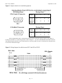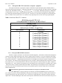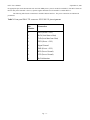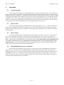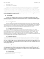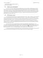
1
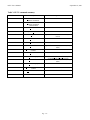
User's Manual
PFCU-4
Filter Set & Relay Control Unit
S/N 01-00nn
XIA LLC
31057 Genstar Rd.
Hayward, CA 94544
Tel: 510-401-5760
Fax: 510-401-5761
www.xia.com
[email protected]
September 25, 2001
Pg. - i-
PFCU User’s Manual
September 25, 2001
Contents:
1.
Warranty and Registration Card ..........................................................................................................................................1
1.1.
Our guarantee policy...................................................................................................................................................1
1.2.
Our repair service .......................................................................................................................................................1
1.3.
Warranty card .............................................................................................................................................................1
2. General product description................................................................................................................................................1
2.1.
Features.......................................................................................................................................................................1
2.2.
Description..................................................................................................................................................................1
2.3.
Technical specifications..............................................................................................................................................2
2.4.
Applications................................................................................................................................................................2
2.5.
Related products .........................................................................................................................................................2
3. Installation ...........................................................................................................................................................................3
3.1.
Unpacking...................................................................................................................................................................3
3.2.
Mechanical installation ...............................................................................................................................................3
3.3.
Electrical connections .................................................................................................................................................3
3.3.1.
Overview.............................................................................................................................................................3
3.3.2.
Back panel: DB-9 connection to PF4, PF2S2, or other controlled equipment ..................................................3
3.3.3.
Back panel: DB-9 TTL connections to computer equipment ...........................................................................5
3.3.4.
Front panel RS-232 DB-9 connectors..................................................................................................................5
4. Initial testing ........................................................................................................................................................................7
4.1.
PFCU initial manual testing........................................................................................................................................7
4.2.
PFCU initial testing under TTL computer control (if implemented) ..........................................................................7
4.3.
PFCU initial testing under RS-232 computer control.................................................................................................7
4.4.
Testing PF4 pneumatic operation ...............................................................................................................................7
5. Operation .............................................................................................................................................................................8
5.1. Normal operation .........................................................................................................................................................8
5.2. Open circuits................................................................................................................................................................8
5.3. Short circuits................................................................................................................................................................8
5.4. Distinguishing between error conditions .....................................................................................................................8
6. PFCU RS-232 interface .......................................................................................................................................................9
6.1. RS-232 setup................................................................................................................................................................9
6.1.1.
Accessing the switches ........................................................................................................................................9
6.1.2.
Setting the module identification number ............................................................................................................9
6.1.3.
Setting the ARB switch........................................................................................................................................9
6.1.4.
Choosing the power source..................................................................................................................................9
6.1.5.
Default settings ....................................................................................................................................................9
6.2. RS232 control enable/disable ....................................................................................................................................10
6.3. PF2S2 shutter control ................................................................................................................................................10
7. PFCU RS-232 command language and responses.............................................................................................................11
7.1. Introduction ...............................................................................................................................................................11
7.2. Command and response syntax, command summary ................................................................................................11
7.3. Detailed language description....................................................................................................................................13
8. Service ...............................................................................................................................................................................17
Pg. - ii -
PFCU User’s Manual
1.
September 25, 2001
Warranty and Registration Card
1.1.
Our guarantee policy
PFCU control units are guaranteed against failure under normal operating conditions for 1 year from time of purchase.
Should a unit fail, it will be repaired or replaced expeditiously in order to minimize disruption to its owner's experiments. In
such an event please call or e-mail us immediately to arrange for free repair service. Be sure to register your instrument.
1.2.
Our repair service
In line with XIA's goal of making your experimental life easier, we also have a repair service which will attempt to
repair, at a reasonable cost, any XIA instrument that fails, whether it is in warranty or not. The components of this service,
which can be selected as your needs require, include:
1: Timely repairs: Our goal is to complete normal repairs in 5 working days or less.
2: Complete testing and checkout before return to assure that the repaired instrument will continue to perform reliably.
3: Loaners: to keep your experiment running if we expect a delay in obtaining necessary replacement parts.
4: Expedited handling: by 2nd day, overnight or if possible, same day rush delivery to get you going again in critical
situations.
1.3.
Warranty card
In order to register your instrument for our guarantee policy, please fill out and return the warranty card at the
bottom of the Warranty Information sheet.
2.
General product description
2.1.
Features
v Implements both manual and computer control of PF4 filter unit, small relays or other experimental equipment
v 4 output lines, each at 24V, 5 - 100 mA, diode protected for inductive loads.
v Outputs switched by front panel switches or remotely using TTL input signals or RS-232.
v Detects both open and short circuits as error states; short circuit protected.
v Panel LEDs show normal activation, flash for errors states.
v Reports normal output activation status with TTL output signals
v Single width NIM module powered either from the NIM bin or alternatively via XIA’s HSC PWR power
adapter block through the RS-232 connector.
2.2.
Description
The Model PFCU-4 is a flexible control unit both for such XIA products as the Model PF4 Filter Inserters and
Model PF2S2 Filter/Shutter Units and for many other types of small experimental equipment. Packaged as a single width
NIM module, it implements both manual control, via front panel switches, and remote control, either via TTL logic inputs
and outputs or through RS-232 commands. It is thereby compatible with a variety of computer I/O modules, including both
CAMAC modules and personal computer I/O cards. Since its 4 output lines are rated for inductive loads of up to 100 mA at
24 Volts, it may also be used to control a variety of other experimental equipment as well, either directly or through the use
of relays.
The Model PFCU-4 has the following control logic for each of its 4 output lines: the output is switched by two ORed inputs (a front panel switch and a remote, Active Lo, input logic level). The resulting output line condition is shown by a
panel LED and output as an Active Lo TTL logic level. In this manner, if remote control is overridden from the front panel,
the actual experimental situation is still reported and can be accurately stored in the remote controller's data record. Currents
of (approximately) less than 3.5 mA or greater than 110 mA are detected and interpreted as "open" and "short" circuit
Pg. - 1-
PFCU User’s Manual
September 25, 2001
conditions, respectively. As a protective feature, the output is switched off in approximately 1 μs following detection of the
short condition and must be reset before normal operation can resume. Both short and open conditions are indicated by
flashing the faulty circuit's front panel LED and switching its output line High.
Note: Both the TTL input and output lines are configured active Lo (0 volts = logic 1)
2.3.
Technical specifications
Physical
SIZE: Single width NIM module.
Power Required (from NIM Bin)
+12 V: 200 mA.
+24 V: up to 400 mA, depending on load.
Inputs
FRONT PANEL: 4 SPST switches "In/Out".
REMOTE INPUT: DB9 M plug, Active Lo TTL levels: 0 Volts = "1" = "In".
Controlled Output
24V, 5 - 100 mA; diode protected for inductive loads.
Connector: DB9 female receptacle.
Status Output
DB9 F receptacle; Active Lo TTL levels: 0 Volts = "1" = "valve actuated".
Fault Detection
Open Circuit: Output currents below 3.5 mA are indicated as open circuits by flashing the circuit's front panel indicator
LED and switching its status output line to "0".
Short Circuit: Output currents above 110 mA are switched off and the condition indicated by flashing the circuit's front
panel LED and switching its status output line to "0". The circuit must be reset (both inputs turned off) before it will
operate normally again.
2.4.
Applications
The PFCU-4 is principally intended for controlling XIA's PF4 and PF2S2 filter and filter-shutter sets. When
purchased with an appropriate connector cable (see below) nothing further is required to implement manual control. To
implement computer control, only user-specific computer-to-PFCU connection cables are required. Using this PFCU/PF4
package, it is simple to automate data collection routines for samples whose x-ray scattering exceeds the dynamic range of
the detector by having the system control computer use the PF4 to adjust the intensity of the x-ray beam via the PFCU
interface. The shutters in the PF2S2 can be used either to time exposures with an accuracy of order 50 ms or to protect
sensitive detectors from excessive beam exposure by turning off the x-ray beam whenever the detector is not actively
engaged in data collection.
With its convenient control system and protected outputs, the PFCU is also well suited for more general
experimental control. It is equally capable of driving solenoids, lamps, small heaters, relays and various electrically operated
valves. Equipment whose power requirements exceed the PFCU's rating may still be controlled through the use of
intermediate relays.
2.5.
Related products
XIA also sells connector cables, designated PF-CAB-xx, that are specifically intended to connect the PFCU to either
a PF4 or a PF2S2 unit. Available lengths xx are 15', 25' & 50'. These are 9 conductor, 26 AWG cables configured as 4
twisted pairs plus ground inside a foil sheath. This arrangement provides exceptional signal immunity to noise in large
facility or industrial environments.
Pg. - 2 -
PFCU User’s Manual
3.
September 25, 2001
Installation
3.1.
ο
ο
ο
Unpacking
When unpacking your PFCU, you should find the following 3 items:
The PFCU control module.
This instruction manual.
A Warranty Card.
Please fill out and return the warranty card before you forget.
The following installation instructions are written assuming that the PFCU will be used to control a PF4 filter set.
For other applications, appropriate changes should be made in the indicated procedures.
3.2.
Mechanical installation
Unless the PFCU will be controlled in RS-232 mode, the only mechanical installation required is to insert the PFCU
into a NIM bin and tighten the front panel thumbscrews. If control will be through RS-232, then certain internal switches
may need to be set. Refer to the section on RS-232 control.
3.3.
Electrical connections
3.3.1.
Overview
Electrical connections to the PFCU are made through 4 DB-9 connectors. Two front-panel connectors allow RS-232
daisy chaining. One back panel connector outputs currents to the controlled PF4 or PF2S2, the other implements TTL input
and output control of the PFCU. Note, this single connector replaces the two front panel TTL connectors used on the
previous version of the PFCU.
3.3.2.
Back panel: DB-9 connection to PF4, PF2S2, or other controlled equipment
Connections between the PFCU and the controlled equipment (e.g. PF4) must be made as shown in the following
sketch, Figure 1.. Please note that the Returns are switched and must be kept as separate leads. The common +24 Volts
may be run as a single lead if desired.
Pg. - 3 -
PFCU User’s Manual
September 25, 2001
Figure 1: Output connector to controlled equipment
Connections from PFCU to controlled equipment
PFCU Back Panel
9 Pin Female D Connector
5
4
9
3
8
2
7
1
6
Pinning Chart
Output
1
2
3
4
Common
+24 V
6
7
8
9
Switched
Return
1
2
4
5
PF4
9 Pin Male D Connector
1
2
6
3
7
4
8
5
Pinning Chart
Valve
1
2
3
4
V+
6
7
8
9
V-
1
2
4
5
9
Cables designated PF-CAB-xx obtained from XIA make these connections with the leads for each output as a
twisted pair and lead #3 as a connecting ground, as shown in Figure 2.. Any cable with DB9 Male and Female connectors
and straight through connections may be used instead if it is rated to produce less than 1 Volt drop for the intended current
over twice the desired cable length.
Figure 2: Wiring diagram for cable between PFCU and PF4 or PF2S2
DB9 - Male
Pin #
DB9 - Female
Pin #
Cable
1
6
2
7
4
8
5
9
3
1
6
2
7
4
8
5
9
3
Connector Shell, if any
Connector Shell, if any
Foil Shield, if any
Foil Shield, if any
Wire Size
26 or 28 Gauge, nominal 0.065 ohm/ft maximum.
Pg. - 4 -
PFCU User’s Manual
3.3.3.
September 25, 2001
Back panel: DB-9 TTL connections to computer equipment
The required connections to appropriate computer controlled TTL input and output registers should be made as
shown in the following sketch, Figure 3. Both inputs and outputs are Low Power Schottky TTL and are therefore compatible
with both TTL and HCMOS circuitry (Vin < 0.5 V for Low, Vin > 2.7 V for High). Both input and output are Active Low,
so that nominal 0 Volts is a logic 1, and grounding an input pin (e.g. 3) will activate the associated PFCU output channel
(#2), causing the equivalent output pin (#3) also to go Low. The active low convention was adopted to ease interfacing the
PFCU to CAMAC control systems where it is common to many input/output devices such as the Joerger QIR and QOR.
Table 1: Back Panel DB-9 TTL Connector
PFCU Revision B TTL I/O
9-Pin Male DB-9 Connector on Back Panel
Pinning Chart
All TTL Signals
Active Low: 0 Volts = Logic True
Pin Number
Connection
Ground
1
Control Input Channel 1
2
Control Input Channel 2
3
Control Input Channel 3
4
Control Input Channel 4
5
Status Output Channel 1
6
Status Output Channel 2
7
Status Output Channel 3
8
Status Output Channel 4
9
3.3.4.
Front panel RS-232 DB-9 connectors
The PFCU supports a standard 3-wire DTE (Data Terminal Equipment) – DCE (Data Communications Equipment)
connection, with no support for hardware flow control or modem control. The PFCU is set to run at 9600 baud, with 8 data
bits, 1 stop bit and no parity. Pin 2 (RxD) carries serial data from the PFCU to the host, while Pin 3 (TxD) carries serial data
from the host to the PFCU. A signal ground connection (Pin 5 on a standard 9-pin serial port connector) completes the 3wire connection. All connections are straight through; no twist (as found in a null-modem DTE-DTE connection) is needed
between Pins 2 and 3. To ensure that the PFCU will work for all serial port flow control settings, Pins 7 (RTS – Request to
Send) and 8 (CTS – Clear to Send) are tied together to provide a hardware flow control loop-back. In addition, Pins 1 (DCD
– Data Carrier Detect), 4 (Data Terminal ready) and 6 (DSR – Data Set Ready) are tied together to form a modem control
loop-back. Pin 9 carries an arbitration signal, used to prevent garbled responses caused by multiple devices attempting to
transmit simultaneously.
Note this arbitration signal must be isolated from the host serial port; see the RS-232 section.
If the HSC-PWR adapter is used to provide power to the PFCU, the RS232 handshaking lines are used to carry
power and power ground. The HSC-PWR adapter cable plugs into the input port of the PFCU, and the cable from the host
serial port plugs into the other end of the cable. The +24 Volt power supply plugs into a small jack on the host end of the
adapter cable. The HSC-PWR adapter cable makes all the loop-back connections on the host end, and connects the power to
Pg. - 5 -
PFCU User’s Manual
September 25, 2001
the appropriate pins on the downstream end. One HSC-PWR power system is needed for each PFCU; if the PFCU shares an
RS-232 daisy chain with HSC-1 devices, separate supplies should be used for the PFCU’s and the HSC-1’s.
The following table lists the connections in the PFCU RS232 interface. The power connections are indicated in
parentheses.
Table 2: Front panel DB-9 TTL connector: PFCU RS-232 pin assignments
Pin
Number
Connection
1
DCD (Power: +24V)
2
RxD (Serial data to Host)
3
TxD (Serial data from Host)
4
DTR (Power: +24V)
5
Signal Ground
6
DSR (Power: +24V)
7
RTS (Power Ground)
8
CTS (Power Ground)
9
RxD Arbitration
Pg. - 6 -
PFCU User’s Manual
4.
September 25, 2001
Initial testing
4.1.
ο
ο
ο
ο
ο
ο
4.2.
ο
ο
ο
ο
ο
ο
ο
ο
PFCU initial manual testing
Install PFCU in NIM Bin
Power up NIM Bin
Throw each front panel switch on PFCU in turn and observe the following:
1: Associated LED on PFCU panel lights up in flashing mode.
Attach Male end of PFCU-PF4 interconnection cable to rear of PFCU, Female end to PF4
Throw each front panel switch on PFCU in turn and observe that the following different things occur:
1: Associated LED on PFCU panel lights up but does not flash.
2: Corresponding PF4 valves LED lights up.
This completes initial manual testing unless you want to throw the switches a few more times.
PFCU initial testing under TTL computer control (if implemented)
Have a computer controlled TTL output register of at least 4 bits and a program to change their values.
Have a computer controlled TTL input register of at least 4 bits and a program to read their values.
With NIM bin and Computer arrays powered off:
1: Connect the PFCU "Control Input" lines to the TTL output bits.
2: Connect the PFCU "Status Output" lines to the TTL input bits.
Turn the NIM bin and Computer arrays power back on.
With all manual switches in OFF position, use the computer to toggle each TTL output bit from 1 to 0 (High to Low)
in turn and observe that the following things all happen:
1: Appropriate PFCU front panel LED comes on.
2: Associated PF4 valve LED comes on.
3: Associated Status bit toggles from 1 to 0 (High to Low).
Also observe that when the output bits are toggled from 0 to 1 (Low to High) the opposite things all happen:
1: Appropriate PFCU front panel LED goes off.
2: Associated PF4 valve LED goes off.
3: Associated Status bit toggles from 1 to 0.
Now, with all computer output bits set to 1 (High), use the front panel switches to turn each valve on and off in turn
and confirm that the same behavior occurs as under computer control. Namely:
1: Appropriate PFCU front panel LED turns on and off.
2: Associated PF4 valve LED turns on and off.
3: Associated Status bit toggles from 1 to 0 and back.
This completes initial TTL computer control testing.
4.3.
PFCU initial testing under RS-232 computer control
Testing operation under RS-232 control involves first setting up the module for RS-232 control, making RS-232
connections between the module and a computer running a program capable of sending out ASCII characters on an RS-232
port, and then running test sequences. Please refer to the RS-232 section for further details.
4.4.
ο
ο
ο
Testing PF4 pneumatic operation
This test can be performed either jointly with the tests of 4.1 and 2 or separately.
In addition to the setup required above, the PF4 must also be attached to a source of high pressure Air or Inert Gas as
per the PF4 instruction manual.
The test procedures are then identical to those of Sections 4.1 and 4.2 above except that an additional visual inspection
is needed to confirm that, when each PF4 valve LED is lighted its corresponding pneumatic cylinder is also
activated, dropping its foil carrier (or their shafts, if the foil carriers have not yet been mounted) into the beam
path.
Pg. - 7 -
PFCU User’s Manual
5.
September 25, 2001
Operation
5.1.
Normal operation
The normal operation of the PFCU is quite straightforward. It consists of 4 identical circuits, cleverly numbered 1
through 4. Each circuit is controlled by 2 two OR-ed inputs (a front panel switch and a remote, Active Lo, input logic level).
Each circuit also has two output lines: a switched power return line and a TTL status output. Because the circuit's two inputs
are logically ORed together, when either the switch is in the "In" position or the input logic level is activated either through
application of a TTL control level or an RS-232 command, the circuit is activated. When the circuit is activated its power
return line is connected to ground through a switching transistor and its TTL status line is switched LO. Any external device
connected between the power return line and the +24 Volts supplied is thereby also activated.
5.2.
Open circuits
The current passing through the switching transistor is sensed and compared to 3.5 mA. A value less than 3.5 mA
when the circuit is supposed to be activated is interpreted as an "Open" circuit and causes the circuit's front panel LED to
flash as well as the output status line to be set HIGH. As soon as the open circuit condition is removed the circuit returns to
normal operation.
5.3.
Short circuits
The current passing through the switching transistor is also compared to a value of 110 mA. A current of greater
than 110 mA is interpreted as a "Short" circuit and causes an internal flip-flop to be set to its "Short circuit detected"
position. This causes the switching transistor to be shut off, the front panel LED to flash, and the output status line to be set
HIGH.. The entire detection and shutoff time is less than a microsecond. Note: When the short circuit condition has been
corrected, the circuit must be reset, by switching both of its inputs OFF, before it can be turned on again to resume
normal operation. Also notice that only short circuits in the controlled circuits are detected. Shorting the supplied +24
Volts to some external ground will not be detected by this module.
5.4.
Distinguishing between error conditions
Because both error conditions are expected to be rare events, the PFCU does not distinguish between them in its
signals to the user. In both cases the front panel light flashes and the output status line goes HIGH. The easiest way to
distinguish between the two cases (after visually checking the connections between the PFCU and the controlled device for
unplugged connectors, etc) is to measure the resistance in the external circuit which is causing the PFCU to go into error
mode. Using the 24V supply, a resistance of greater than 6800 Ω will result in the open circuit condition. A resistance of
less than 220 Ω will result in a short circuit condition.
Pg. - 8 -
PFCU User’s Manual
6.
September 25, 2001
PFCU RS-232 interface
In addition to the front panel switches and the TTL digital interface, the PFCU can now be controlled through its
front panel RS232 interface. A simple set of commands allows control and monitoring of the state of the X-ray filters.
Connecting the PFCU to a computer is as easy as running a cable between a standard computer serial port and the “In” port
on the PFCU. To control more than one PFCU with the same serial port, just daisy chain them together, by connecting the
“Out” port of one PFCU to the “In port of the next PFCU. Up to 16 PFCU’s can be included in the daisy chain. In addition,
the PFCU can be included in the same RS232 daisy chain as the XIA Model HSC-1 Huber Slit controller, providing unified
control for an X-ray beamline. In such a setup, it is also possible to provide power to the PFCU through the RS232 interface,
using the HSC-PWR adapter cable and power supply.
6.1.
RS-232 setup
To run the PFCU with RS-232 control, it is necessary to set several DIP switches that determine the module
identification and whether the arbitration line is connected to the Input connector. In addition, to power the PFCU through
the RS-232 interface, another printed circuit board mounted switch must be set to choose RS232 power (instead of getting
power from the NIM crate).
6.1.1.
Accessing the switches
In order to gain access to the switches on the printed circuit board, orient the PFCU flat on a bench with the NIM
connector in the lower left corner. Remove the five screws that attach the side panel to the frame, and remove the side panel.
The 5-position DIP switch S6 is located just behind the output RS-232 connector, labeled “RS232 Settings.” The sliding
switch S1 is located next to the 3-pin connector for the NIM power connections, labeled “Power Source.”
6.1.2.
Setting the module identification number
In order to address more than one PFCU on a serial daisy chain, each module must have a unique Module
Identification. Four bits are used to set the identification number, allowing control of up to 16 PFCU’s with a single serial
port. To set the identification number, use the 4 positions of the DIP switch labeled “ID1”, “ID2”, “ID4” and “ID8” to
choose a number between 0 and 15. Setting the switch to the “On” position sets the corresponding bit. As shipped, the
identification number is set to zero (all bits off). When the module is powered on, the identification bits are displayed briefly
on the front panel LED’s (the Channel 0 LED corresponds to bit 0 and so on).
6.1.3.
Setting the ARB switch
The remaining position on the DIP switch, labeled “ARB”, determines whether the arbitration pin (Pin 9) on the input RS232 connector is connected to the arbitration line, which is used by daisy-chained devices to avoid conflict over using the
RxD line to send data back to the host. The host should be isolated from the arbitration line; therefore, the “ARB” switch
should be set to “Off” on the first device on a daisy chain (the closest one to the host). All other devices should have “ARB”
set to “On”. As shipped, “ARB” is set to “Off”. If the PFCU shares a daisy chain with one or more HSC-1 devices, be sure
to set the jumpers on the HSC-1’s appropriately (only the first device of either type in the daisy chain should isolate the input
connector from the arbitration line).
6.1.4.
Choosing the power source
The PFCU can either be powered from the NIM bin or through the RS-232 interface, using the HSC-PWR adapter.
If the PFCU is powered through the front panel RS-232 interface, it does not need to sit in the NIM bin; it can sit anywhere,
even inside the hutch. Please recall that one HSC-PWR supply and adapter is needed for each PFCU in the daisy chain.
Switch S1 is used to choose the power source for the PFCU; set it to “RS232” to power it from the front panel. As shipped,
the PFCU is set up to use the NIM power.
6.1.5.
〈
Default settings
As specified above, the default RS-232 settings are:
Module Identification Number:0
Pg. - 9 -
PFCU User’s Manual
〈
〈
September 25, 2001
Arbitration line isolated from Input connector
Power from the NIM bin
6.2.
RS232 control enable/disable
There are several ways to control the filters using the PFCU: front panel switches, TTL digital inputs through a
connector on the rear panel, and control through RS232 commands. RS232 control of the filters can be disabled using the
slide switch at the top of the front panel: RS232 commands cannot affect the state of the filters unless this switch is in the
“ON” state (non-control RS232 commands operate normally). This feature allows emergency control of the filters with the
front panel switches (or TTL inputs) if the RS232 connection fails. Momentarily disabling RS232 control clears all the
RS232 control bits into their ‘OUT’ state.
6.3.
PF2S2 shutter control
The XIA Model PF2S2 incorporates a focal plane shutter in place of filters 3 and 4. The shutter is open if position 3
is in the inserted state and position 4 is in the retracted state; the shutter is closed in the three other combinations of states.
The state with both positions retracted is the normal “starting” closed state; the other two closed states are used in transition
from shutter open to shutter closed. To switch from the starting closed state (OUT,OUT) to the open state (IN,OUT),
position 3 is inserted. To then move from the open state to the closed state, position 4 is inserted (IN,IN). To prepare for
another opening cycle (without passing additional beam through the shutter), position 3 is retracted (OUT,IN), and finally
position 4 is retracted (OUT,OUT).
The PFCU offers several commands to control the shutter in the PF2S2: Open, Close and Exposure. These
commands are only enabled if Shutter Mode is enabled using the 2 command (as in PF2S2); Shutter Mode is disabled using
the 4 command. By default, Shutter Mode is disabled. The basic time unit for the Exposure command is set using the
Decimation command. See below for detailed descriptions of the commands used to control the shutter.
Note that Shutter Mode does not disable other sources of control for positions 3 and 4; the shutter can be opened or
closed by non-shutter RS232 commands, as well as the front panel switches or TTL inputs (if enabled).
Pg. - 10 -
PFCU User’s Manual
7.
September 25, 2001
PFCU RS-232 command language and responses
7.1.
Introduction
This section describes the commands used to control the PFCU, as well as the responses returned by the PFCU to
each command. The command syntax is easy to use, so that manual control through a terminal is a definite alternative to
computer control.
In the following sections, command text is in boldface Arial font:
!A command to the PFCU looks like this
(Note that command text is not case sensitive.)
Response text from the PFCU is in Courier New font:
%A response from the PFCU looks like this;
7.2.
Command and response syntax, command summary
The PFCU uses a very simple command language, using single-character, easy to remember mnemonic commands.
The basic command syntax is as follows:
!Module-IdCommand Arg1 Arg2 Arg3 … <carriage return>
The space between the Module-Id and the command is required (indicated by the ); no other spaces are required (but
can be included without adverse effect). Note that the length of the command line may not exceed 32 characters.
The Module-Id is PFCUnn where nn is the numeric identification number set using the DIP switches, ranging from
00 to 15. To address all PFCU modules in the daisy chain, use the special PFCUALL Module-Id. Note that the Module-Id
is not case sensitive.
The Command is a single character. See Table 3 below for a list of available commands, and the following section
for a detailed description of each command.
The number of arguments depends on the command; the maximum number of arguments is four (extra arguments
are ignored). Most arguments are single characters; no space is needed between the command and the first argument, or
between single character arguments. See Table 2 and the next section for descriptions of the arguments for each command.
The responses from the HSC take the following form:
%Module-Id Response text;<Carriage Return>
All responses will begin with the ‘%’ character, followed immediately by the Module-Id. The response text is
described below along with the detailed description of each command; note that there may be carriage returns in the
response. The response is ended by a ‘;’ character followed by a carriage return.
After receiving a command, the HSC-1 will immediately return a response indicating the status of the command.
The two possible responses are OK and ERROR. OK indicates that the command was received and is being processed.
ERROR, followed by an error code and a brief description of the error, indicates that there is a problem and the command
cannot be processed.
Pg. - 11 -
PFCU User’s Manual
September 25, 2001
Table 3: PFCU command summary
Command
Description
Arguments
2
None
C
PF2S2 Mode
Enable
shutter commands
PF4 Mode
Disable
shutter commands
(initial default)
Close shutter
D
Exposure Decimation
Decimation value (1 to 65535)
E
Exposure
F
Fault Status
Exposure Time / (Decimation*10 ms) (1 to
65535)
None
H
SHutter Status
None
I
Insert Filter
L
O
Lock: ignore non-RS232
controls
Open shutter
P
Position Inquiry
R
Remove Filter
S
Status Display
U
W
Unlock: enable non-RS232
Control
Write Filter Position
0 or 1 for each filter
Z
Clear Short Error condition
None
4
None
None
Up to 4 filter numbers 1, 2, 3 or 4
order)
None
(in any
None
Control Source (RS232,Panel,TTL) (optional
– no argument gives overall setting)
Up to 4 filter numbers 1, 2, 3 or 4 (in any
order)
None
None
Pg. - 12 -
PFCU User’s Manual
7.3.
September 25, 2001
Detailed language description
This section describes each command in detail, and lists the possible responses.
2: Enable PF2S2 shutter commands
This command enables the shutter commands (Close, Open, Exposure) useful for controlling the XIA Model PF2S2 Filter
unit with focal plane shutter. When power is first applied to the PFCU, the shutter commands are disabled. Note that RS232
control must also be enabled (using the front panel switch) in order for the shutter commands to work.
Syntax: !Module-Id 2
Returns:
%Module-Id OK Shutter Mode Enabled DONE;
4: Disable PF2S2 shutter commands
This command disables the shutter commands. This is the default condition at power-up.
Syntax: !Module-Id 4
Returns:
%Module-Id OK Shutter Mode Disabled DONE;
C: Close shutter (applicable to PF2S2 only)
This command immediately closes the PF2S2 shutter. If an exposure initiated by the E command is in progress, the exposure
is terminated. This command takes no arguments (any arguments are ignored). This command only works if shutter mode is
enabled.
Syntax: !Module-Id C
Returns:
%Module-Id End of Exposure;
if an exposure is in progress, then
%Module-Id OK Shutter Closed DONE;
There are two possible errors:
%Module-Id ERROR: RS232 Control Disabled;
or
%Module-Id ERROR: Shutter mode disabled;
D: Set exposure decimation value
This command sets the basic time unit for the exposure command, in units of 10 milliseconds. The decimation value can
range from 1 to 65535. On power-up, the decimation value is set to 1. Note that this command will work (with little effect
…) even if shutter mode is disabled.
Syntax: !Module-Id D [Decimation Value]
Returns:
%Module-Id OK Decimation = [value] DONE;
if the specified value is valid, or
%Module-Id ERROR: Invalid Decimation Value;
if the specified value is out of range or contains illegal characters.
E: Start exposure (applicable to PF2S2 only)
This command is enabled only in shutter mode (and RS232 control is enabled). This command initiates a fixed length
exposure using the focal plane shutter; the exposure time is specified as a multiple of decimated time units (see the D
command above), with a minimum time unit of 10 milliseconds. The exposure can range from 10 milliseconds (with an
argument of 1 and decimation=1) to nearly 500 days (with the maximum argument of 65535 and decimation=65535). Note
that the switching time of the pneumatic switches is roughly 20 ms and the movement time of the shutter leaf is longer, so
very short exposures may not be repeatable or accurate (measured as a fraction of the exposure time).
Syntax: !Module-Id E [Exposure Time]
Returns:
%Module-Id OK Exposure Started;
when the exposure is started, and
%Module-Id End of Exposure DONE;
when the exposure is complete.
There are three possible errors:
Pg. - 13 -
PFCU User’s Manual
September 25, 2001
%Module-Id ERROR: RS232 Control Disabled;
or
%Module-Id ERROR: Shutter mode disabled;
or
%Module-Id ERROR: Invalid Exposure Time;
F: Fault status
This command returns the full status of each channel, indicating whether the corresponding filter is in or out, as well as
whether a fault (either a short or an open circuit) has been detected. The PFCU returns a code for each filter; 0 indicates that
the filter is out, 1 indicates that the filter is inserted with no fault condition, 2 indicates an open circuit, and 3 indicates a short
circuit. In either fault condition, the filter is likely not inserted. If the channel indicates open, power is applied but no
current is flowing, most likely due to a bad connection in the cable (or the cable is not plugged in). In the short condition,
power to the filters is disabled. To clear the short condition, the channel must be turned off, or a Z command must be issued.
Note that the channel must be enabled in order to detect a short or open circuit.
Syntax: !Module-Id F
Returns:
%Module-Id OK abcd DONE;
where a, b, c and d are the return codes for filters 1 through 4 respectively:
0:
Filter out
1:
Filter In, all OK
2:
Open circuit detected
3:
Short circuit detected
H: Shutter status
This command is used to check the status of the shutter when operating in shutter mode. If the PFCU is not in shutter mode,
an error is returned.
Syntax: !Module-Id H
Returns:
%Module-Id OK Shutter Open DONE;
or
%Module-Id OK Shutter Closed DONE;
If the PFCU is not in shutter mode, the following message is returned:
%Module-Id ERROR: Shutter mode disabled;
I: Insert filter
This command is used to insert one or more filters. The numbers of the filters to be inserted follow the command character
(I); no spaces are needed between the command character and the filter list, or in the filter list itself (but they can be included
if desired). Filter numbers range from 1 to 4; any other characters are ignored.
Syntax: !Module-Id I[nmpq]
where n, m, p and q are filter numbers (only one is necessary).
Returns:
%Module-Id OK abcd DONE;
where abcd gives the state of each filter (0:off, 1:on, 2:open, 3:short) as described above in the description of the F
command.
If there are no valid arguments, an error message is returned:
%Module-Id ERROR: No Valid Arguments;
L: Lock: RS232 control only
This command is used to set the PFCU such that the non-RS232 controls are ignored. This means that the front panel
switches and the TTL control lines would be ignored, until either an unlock command is issued (see below) or RS232 control
is disabled (using the front panel slide switch).
Syntax: !Module-Id L
Returns:
%Module-Id OK Locked DONE;
If RS232 control is not enabled, the following error message is returned:
%Module-Id ERROR: RS232 Control Disabled;
Pg. - 14 -
PFCU User’s Manual
September 25, 2001
O: Open shutter (applicable to PF2S2 only)
This command immediately opens the PF2S2 shutter, beginning an indefinite exposure. For a timed exposure, use the E
command described above. This command takes no arguments (any arguments are ignored). This command only works if
shutter mode is enabled.
Syntax: !Module-Id C
Returns:
%Module-Id OK Shutter Open DONE;
There are two possible errors:
%Module-Id ERROR: RS232 Control Disabled;
or
%Module-Id ERROR: Shutter mode disabled;
P: Position inquiry
This command is used to determine the current settings for the filters. By default (no arguments), the overall settings for the
filters is returned, which combines the RS232, front panel and TTL control inputs. To determine the control settings from
just one source, use an argument R to specify RS232, P to specify the front panel switches, and T to specify the TTL inputs.
Note that the returned values reflect only the desired filter state, and do not reflect whether the filter insertion is disabled do
to a short or open condition.
Syntax: !Module-Id P [Control source: no arg overall state]
Returns:
%Module-Id OK abcd DONE;
where abcd gives the state of each filter (a corresponds to filter 1 etc), with a ‘1’ meaning the filter is inserted and a ‘0’
meaning the filter is removed.
If the specified argument is invalid, the following message is generated:
%Module-Id ERROR: No Valid Arguments;
R: Remove filter
This command is the complement of the ‘I’ command above. It is used to remove one or more filters, and has the same
syntactic structure as the insertion command.
Syntax: !Module-Id R[nmpq]
where n, m, p and q are filter numbers (only one is necessary).
Returns:
%Module-Id OK abcd DONE;
where abcd gives the state of each filter (0:off, 1:on, 2:open, 3:short) as described above in the description of the F
command.
If there are no valid arguments, an error message is returned:
%Module-Id ERROR: No Valid Arguments;
S: Status report
This command produces a full status report, giving all information for each channel, as well as the value of the system
control variables.
Syntax: !Module-Id S
Returns (for example):
%Module-Id OK PFCU v1.0 (c) XIA 1999 All Rights Reserved
CHANNEL IN/OUT FPanel TTL RS232 Shorted? Open?
1
IN
OUT
OUT
IN
NO
NO
2
IN
IN
OUT
OUT
YES
NO
3
OUT
OUT
OUT
OUT
NO
NO
4
IN
OUT
IN
OUT
NO
NO
RS232 Control Enabled: YES
RS232 Control Only:
NO
Shutter Mode Enabled:
NO
Pg. - 15 -
PFCU User’s Manual
Exposure Decimation:
September 25, 2001
10
U: Unlock: enable all control sources
This command unlocks exclusive RS232 control and allows filter control by the front panel switches and the TTL inputs, as
well as RS232 commands (as long as RS232 control is enabled with the front panel switch). It is the opposite of the Lock
command above.
Syntax: !Module-Id U
Returns:
%Module-Id OK Unlocked DONE;
W: Write filter state
This command offers an alternate method to the I and R commands to set the filter state. In this command, the first argument
determines the state of filter 1, etc. It is not necessary to provide all four arguments, except to control filter 4. Any
arguments beyond the fourth are ignored. For each filter, a ‘0’ indicates that the filter should be removed, a ‘1’ indicates that
the filter should be inserted, and an ‘=’ indicates that the filter should not change state. Note: all characters except ‘0’ and
‘=’ are treated as a ‘1’. Also note that no spaces are necessary between arguments.
Syntax: !Module-Id W pqrs
where p indicates the desired state of filter 1, q the desired state of filter 2, etc.
Returns:
%Module-Id OK abcd DONE;
where abcd gives the state of each filter (0:off, 1:on, 2:open, 3:short) as described above in the description of the F
command.
If there are no arguments, an error message is returned:
%Module-Id ERROR: No Valid Arguments;
Z: Clear short error condition
This command clears any short conditions existing on any of the 4 channels. When a short condition is detected, power is
immediately removed, and the short condition is latched. To clear the latched short state, the channel must be turned off by
all enabled control inputs (ie, the overall control state for the shorted channel must be set to the ‘OUT’ state), or a Z
command must be issued. This command very briefly sets all channels to the ‘OUT’ state then returns the channels to their
original state. The cycle time is much much shorter than the response time of the filters, so non-shorted filters are not
affected.
Syntax: !Module-Id Z
Returns:
%Module-Id OK abcd DONE;
where abcd reports the status of each filter as defined above.
Pg. - 16 -
PFCU User’s Manual
8.
September 25, 2001
Service
If its warranty period has not expired we recommend that a malfunctioning unit be returned to XIA for repair. If
your unit is out of warranty it still can be serviced. To return an item you must request a Return Material Authorization
(RMA) number.
Pg. - 17 -