1
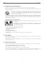
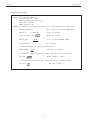
C3i - CR3i
Jouan 4 x 280 mL Multifunction Centrifuges
User’s Manual
Manual N°: 89003152-a
C3i-CR3i
CAREFULLY READ THIS MANUAL BEFORE OPERATING YOUR INSTRUMENT.
INFORMATION CONTAINED IN THIS DOCUMENT IS THE PROPERTY OF
THERMO ELECTRON CORPORATION;
IT MAY NOT BE DUPLICATED OR DISTRIBUTED WITHOUT THE OWNER’S AUTHORIZATION.
THE VALIDITY OF THE GUARANTEE IS SUBJECT TO THE OBSERVATION OF THE INSTRUCTIONS
AND PRECAUTIONS DESCRIBED IN THIS DOCUMENT
C3i-CR3i
Revision Status
Revision Status
REV
DATE
a
07/04
AMENDED PAGES
NOTES
Initial release
C3i-CR3i
Packing List
Packing List
c
c
c
c
11175770
11175771
Centrifuge C3i
Centrifuge C3i
230V 50/60 Hz
120V 60 Hz
11175774
11175775
Centrifuge CR3i
Centrifuge CR3i
230V 50/60 Hz
120V 60 Hz
Item
Item
number
number
89002796
64227001
26915005
26792017
26792017
86004061
86003941
Quantity
Centrifuge
Centrifuge A14i micron - 230V 50/60 Hz
AA24.13 - Rotor 24 x 1,5/2,2 mL
User manual
User manual
CE Declaration of compliance
Mains lead
Manual lid opening instructions
Lid opening tool
Mains cord
Rotor locking nut
Toolbox :
Rotor locking washer
- Rotor removal tool
Rotor locking wrench
- Emergency unlocking tool
Fuse 5X20 3.15A T 250V
- Spare fuses (C3i only)
For missing parts call your nearest Thermo representative
1
1
1
1
1
1
1
1
1
1
1
1
1
1
2
2
Check
Check
c
c
c
c
c
c
c
c
c
c
c
c
c
c
c
c
C3i-CR3i
Guarantee Terms
Guarantee Terms
JOUAN guarantees that this unit is free from defects in materials and workmanship when it leaves the factory,
and will replace or repair the unit if it proves defective in normal use or during service for a period of ONE YEAR
from the delivery.
Our liability under this guarantee is limited to repairing the defective unit or any part of the unit providing it is
sent, postage paid, to an authorized service center or the SAINT-HERBLAIN office.
This guarantee is invalid if the unit is incorrectly used, poorly serviced or neglected, mis-used or accidentally
damaged.
There is no explicit guarantee other than as stated above.
For further information, assistance or service :
Belgium :
India :
UK :
Brussels
Phone +32 2 482 30 30
Fax. +32 2 482 30 31
Navi Mumbai
Phone +91 22 2778 1101
Fax +91 22 2778 1103
Basingstoke, Hampshire
Phone +44 870 609 9203
Fax. +44 870 609 9202
China :
Italy :
USA / Canada :
Beijing
Phone +86 10 5850 3588
Fax. +86 10 6621 0847
Cologno Monzese (MI)
Phone +39 (02) 253 90889
Fax +39 (02) 253 8922
Milford, MA
Phone +1 866-9 THERMO (984-3766)
Fax. +1 (508) 634 2199
Shanghai
Phone +86 21 5465 7588
Fax. +86 21 6445 7830
Japan :
Winchester, VA
Phone +1 (540) 869 8623
Fax. +1 (540) 869 8626
Denmark :
Allerød
Phone +45 48 16 62 00
Fax. +45 48 16 62 97
Finland :
Vantaa
Phone +358 9 329 100
Fax. +358 9 3291 0414
France :
Saint-Herblain (Nantes)
Phone +33 (0) 2 28 03 20 00
Fax. +33 (0) 2 28 03 20 01
Yokohama City
Phone +81 45 453 9122
Fax +81 45 453 9222
Netherlands :
Breda
Phone +31 76 571 4440
Fax. +31 76 587 9757
Other Countries :
Europe
Phone +44 870 609 9203
Fax. +44 870 609 9202
Russia :
Nordic Countries
Phone +45 48 16 62 00
Fax. +45 48 16 62 97
Moscow
Phone +7 095 755 9045
Fax. +7 095 755 9046
Outside Europe
Phone +33 (0) 2 28 03 20 00
Fax. +33 (0) 2 28 03 20 01
Spain :
Germany :
Barcelona
Phone +34 93 2233154
Fax. +34 93 2230857
Dreieich
Phone +49 6103 408 0
Fax. +49 6103 408 1222
Madrid
Phone +34 9165 74930
Fax. +34 9165 74937
Hong Kong :
Sweden :
Wanchai
Phone +852 2885 4613
Fax. +852 2567 4447
Stockholm
Phone +46 8 742 03 90
Fax. +46 8 742 09 47
Website : www.thermo.com
C3i-CR3i
Contents
Contents
1
2
3
Use and Function . . . . . . . . . . . . . . . . . . . . . . . . . . . . . . . . . . . . . . . . . . . . . . . . . . . . . . . . . . . . . . . .
1
1.1.
1.2.
1.3.
1.4.
1.5.
1.6.
1.7.
1.8.
User Manual . . . . . . . . . . . . . . . . . . . . . . . . . . . . . . . . . . . . . . . . . . . . . . . . . . . . . . . . . . . . .
Warning Symbols . . . . . . . . . . . . . . . . . . . . . . . . . . . . . . . . . . . . . . . . . . . . . . . . . . . . . . . . . .
Description . . . . . . . . . . . . . . . . . . . . . . . . . . . . . . . . . . . . . . . . . . . . . . . . . . . . . . . . . . . . . .
Refrigeration and Heating Systems . . . . . . . . . . . . . . . . . . . . . . . . . . . . . . . . . . . . . . . . . . . .
Drive System . . . . . . . . . . . . . . . . . . . . . . . . . . . . . . . . . . . . . . . . . . . . . . . . . . . . . . . . . . . . .
Safety Interlock System . . . . . . . . . . . . . . . . . . . . . . . . . . . . . . . . . . . . . . . . . . . . . . . . . . . . .
Imbalance Detection System . . . . . . . . . . . . . . . . . . . . . . . . . . . . . . . . . . . . . . . . . . . . . . . . . .
Relative Centrifugal Force . . . . . . . . . . . . . . . . . . . . . . . . . . . . . . . . . . . . . . . . . . . . . . . . . . .
1
1
1
2
2
2
3
3
Specifications . . . . . . . . . . . . . . . . . . . . . . . . . . . . . . . . . . . . . . . . . . . . . . . . . . . . . . . . . . . . . . . . . . .
5
2.1.
2.2.
2.3.
Dimensions and Weight . . . . . . . . . . . . . . . . . . . . . . . . . . . . . . . . . . . . . . . . . . . . . . . . . . . . .
Electrical Specifications . . . . . . . . . . . . . . . . . . . . . . . . . . . . . . . . . . . . . . . . . . . . . . . . . . . . .
Performance . . . . . . . . . . . . . . . . . . . . . . . . . . . . . . . . . . . . . . . . . . . . . . . . . . . . . . . . . . . . . .
5
5
5
Installation . . . . . . . . . . . . . . . . . . . . . . . . . . . . . . . . . . . . . . . . . . . . . . . . . . . . . . . . . . . . . . . . . . . . .
7
3.1.
3.2.
3.3.
3.4.
3.5.
3.6.
3.7.
4
5
6
7
Environmental Conditions . . . . . . . . . . . . . . . . . . . . . . . . . . . . . . . . . . . . . . . . . . . . . . . . . . .
Unpacking . . . . . . . . . . . . . . . . . . . . . . . . . . . . . . . . . . . . . . . . . . . . . . . . . . . . . . . . . . . . . . .
Positioning . . . . . . . . . . . . . . . . . . . . . . . . . . . . . . . . . . . . . . . . . . . . . . . . . . . . . . . . . . . . . . .
Mains Supply . . . . . . . . . . . . . . . . . . . . . . . . . . . . . . . . . . . . . . . . . . . . . . . . . . . . . . . . . . . . .
Lid Opening and Rotor Checking . . . . . . . . . . . . . . . . . . . . . . . . . . . . . . . . . . . . . . . . . . . . .
Manual Lid Unlocking Procedure . . . . . . . . . . . . . . . . . . . . . . . . . . . . . . . . . . . . . . . . . . . . .
Performance and Accessories . . . . . . . . . . . . . . . . . . . . . . . . . . . . . . . . . . . . . . . . . . . . . . . . .
7
7
7
8
8
9
10
Instructions for Use . . . . . . . . . . . . . . . . . . . . . . . . . . . . . . . . . . . . . . . . . . . . . . . . . . . . . . . . . . . . . .
13
4.1.
4.2.
4.3.
4.4.
4.5.
4.6.
4.7.
Controls and Indicators . . . . . . . . . . . . . . . . . . . . . . . . . . . . . . . . . . . . . . . . . . . . . . . . . . . . .
Display Screens . . . . . . . . . . . . . . . . . . . . . . . . . . . . . . . . . . . . . . . . . . . . . . . . . . . . . . . . . . .
Control Panel Functions . . . . . . . . . . . . . . . . . . . . . . . . . . . . . . . . . . . . . . . . . . . . . . . . . . . . .
Control Panel Indicators . . . . . . . . . . . . . . . . . . . . . . . . . . . . . . . . . . . . . . . . . . . . . . . . . . . .
Description of Certain Events with Respect to the Control System . . . . . . . . . . . . . . . . . . . .
Preparing the First Run of the Day . . . . . . . . . . . . . . . . . . . . . . . . . . . . . . . . . . . . . . . . . . . . .
Sample Loading . . . . . . . . . . . . . . . . . . . . . . . . . . . . . . . . . . . . . . . . . . . . . . . . . . . . . . . . . . .
13
14
14
15
16
16
17
Hazards, Precautions and Limitations of Use . . . . . . . . . . . . . . . . . . . . . . . . . . . . . . . . . . . . . . . . . . .
19
5.1.
5.2.
5.3.
5.4.
5.5.
IEC 1010-2-020 . . . . . . . . . . . . . . . . . . . . . . . . . . . . . . . . . . . . . . . . . . . . . . . . . . . . . . . . . . .
Cautions . . . . . . . . . . . . . . . . . . . . . . . . . . . . . . . . . . . . . . . . . . . . . . . . . . . . . . . . . . . . . . . .
Speed Control . . . . . . . . . . . . . . . . . . . . . . . . . . . . . . . . . . . . . . . . . . . . . . . . . . . . . . . . . . . .
Operational Limitations . . . . . . . . . . . . . . . . . . . . . . . . . . . . . . . . . . . . . . . . . . . . . . . . . . . . .
Aerosol Risks . . . . . . . . . . . . . . . . . . . . . . . . . . . . . . . . . . . . . . . . . . . . . . . . . . . . . . . . . . . . .
19
19
19
20
20
Service and Maintenance . . . . . . . . . . . . . . . . . . . . . . . . . . . . . . . . . . . . . . . . . . . . . . . . . . . . . . . . . .
21
6.1.
6.2.
6.3.
6.4.
6.5.
6.6.
6.7.
Periodic Cleaning . . . . . . . . . . . . . . . . . . . . . . . . . . . . . . . . . . . . . . . . . . . . . . . . . . . . . . . . . .
Contamination Hazards . . . . . . . . . . . . . . . . . . . . . . . . . . . . . . . . . . . . . . . . . . . . . . . . . . . . .
Disinfection . . . . . . . . . . . . . . . . . . . . . . . . . . . . . . . . . . . . . . . . . . . . . . . . . . . . . . . . . . . . . .
Radioactive Decontamination . . . . . . . . . . . . . . . . . . . . . . . . . . . . . . . . . . . . . . . . . . . . . . . .
Power Supply Circuit Breaker . . . . . . . . . . . . . . . . . . . . . . . . . . . . . . . . . . . . . . . . . . . . . . . .
Rotor Removal . . . . . . . . . . . . . . . . . . . . . . . . . . . . . . . . . . . . . . . . . . . . . . . . . . . . . . . . . . .
Trunnion Lubrication . . . . . . . . . . . . . . . . . . . . . . . . . . . . . . . . . . . . . . . . . . . . . . . . . . . . . .
21
21
21
22
22
22
23
6.8.
Chemical Compatibility Table for Rotors, Tubes and Accessories . . . . . . . . . . . . . . . . . . . . .
24
Disposal of Product . . . . . . . . . . . . . . . . . . . . . . . . . . . . . . . . . . . . . . . . . . . . . . . . . . . . . . . . . . . . . .
29
C3i-CR3i
1
Use and Function
Use and Function
1.1. User Manual
The user manual is part of the centrifuge, and contains important information for your safety and for the
best use of the equipment
Always keep the manual close to the appliance and in a safe place, so that it is always available. Thermo
strongly recommends that all users read this manual carefully.
1.2. Warning Symbols
The following symbols are provided to help the operator take advantage of the protection afforded by the
equipment and to warn of potential danger.
I
O
On the main switch, allows centrifuge to operate.
On the main switch, disconnects the centrifuge from the main power supply.
Only authorized personnel can touch the parts close to this symbol and, in any case, only after
switching off the main power supply. Coming in contact with high voltages could cause severe
injuries.
In this manual, this symbol means that you will find important information for safety, which if
unobserved could result in damage to the appliance and/or harm to the operator.
In this manual, this symbol means that you will find important information about minimizing
biological risk : if unobserved the result could be harm to the operator.
1.3. Description
The C3i and CR3i centrifuges are designed for laboratory use.
They will separate the components of fluids into layers of varying density by subjecting them to high forces.
Centrifugal force provided by the centrifuge can also be used to drive solvents and low molecular weight
solutes through the membrane of a filtering device. Retained macrosolutes will therefore be found above
the membrane.
Relative Centrifugal Force (RCF) generated by a rotor is directly proportional to its sedimentation useful
radius and to the value of its speed squared.
A control system permits the user, through an extremely intuitive control panel, to set and control the
speed, the g-force, the temperature (on the thermostated and refrigerated versions) and the run time, as well
as to view different messages and warnings.
1
C3i-CR3i
Use and Function
1.4. Refrigeration and Heating Systems
The C3i is a ventilated unit. A permanent air circulation reduces the heat level in the bowl.
However the temperature in the bowl can exceed 10 °C above the ambient temperature after hours of
continuous operation.
The CR3i is equipped with a powerful refrigeration system that allows samples to be
processed at low temperature. The refrigerant, R134a, is free of CFC (Chloro-FluoroCarbons) in accordance with the Montreal Protocol directions for preservation of the
ozone layer in the atmosphere.
The actual temperature in the bowl is continuously displayed on the front panel of the centrifuge. Under
certain conditions (high speed, long duration runs) the sample temperature can be higher than the bowl
temperature on the display. In this case, the user may compensate manually after empirical determination
of the temperature differential.
Condensation drain on refrigerated units
The lid should remain closed when the refrigeration system is in use to avoid
condensation.
The centrifuge has a rubber hose that allows condensation to be drained from the
bowl. The drain hose exits at the back of the machine. Near the drain hose you
can find the following label:
To remove condensation, please follow this procedure:
-
Switch off the centrifuge and disconnect the power.
Put a small basin under the hose.
Unplug the hose.
Drain the centrifuge bowl.
Insert the plug back into the hose.
ATTENTION: Do not remove the plug from the drain hose during centrifugation.
1.5. Drive System
A three phase brushless motor drives the rotating equipment. The rotor is contained in a sealed, armor
plated centrifugation chamber.
The brushless motor requires no maintenance. A control system ensures the correct drive speed, which is
continuously monitored.
1.6. Safety Interlock System
The C3i and CR3i centrifuges are equipped with an interlock system that assures two basic safety features:
- The run cannot be started if the lid is not correctly closed.
- The centrifuge lid cannot be opened if the rotor is running.
The centrifuge will not operate until the lid is closed and latched in place.
The lid remains latched until the rotor stops spinning. The lid access lamp indicates when the rotor has
stopped: consequently the handle on the right hand side of the centrifuge can be used to open the lid.
2
C3i-CR3i
Use and Function
If a power failure occurs, access to the samples in the centrifuge is possible via a manual lid opening
procedure (see appropriate paragraph). For this operation a special tool (supplied with the centrifuge) is
required.
Bypass the interlock system only under emergency conditions as the rotor could still be rotating.
1.7. Imbalance Detection System
The C3i centrifuge is equipped with a load imbalance detector.
In case of excessive imbalance, the load imbalance indicator LED is illuminated and the brake is applied
immediately. The rotor will be decelerated to rest in few seconds.
As soon as the motor stops, open the centrifuge and redistribute the samples to produce an equal weight on
diametrically opposite sides.
If the message persists, despite your efforts to balance the load, call your Thermo Service representative.
Note : Imbalance tolerance depends upon the rotor in use. The centrifuge will tolerate 10 gr. of imbalance
with the 4 x 280 mL rotor equipped with standard buckets. Carefully balance the sample load to avoid
actuating the imbalance detection system.
1.8. Relative Centrifugal Force
Relative Centrifugal Force (RCF), at the circumference of a rotor and bucket combination, is directly
proportional to the speed (r.p.m.) and radius of the rotor. Therefore, a greater r.p.m. and/or a larger radius
produces a greater RCF and improved faster separation of substances. The centrifuge control system carries
out and displays the results of all calculations related to speed, radius and RCF.
Note : The value introduced for the radius can be adjusted to allow for position within the tube such as at a
boundary. Maximum radii are quoted in the specifications tables. Use of improper radius will adjust the
speed setting, automatically applying the wrong RCF.
3
C3i-CR3i
Use and Function
Centrifugation formulae
Legend : R = radius (in millimetres)
N = speed (in r.p.m.) ÷ 1000
RCF = gravitational acceleration ‘g’
M+ = add to memory
MR = memory recall
NOTE : To calculate actual results, press the keys on a pocket calculator in the order shown.
Primary calculations
Key sequence (not valid for CASIO, HP)
RCF (x g)
= 1.118 R N2
N x = x 1.118 x R =
Speed (r.p.m.)
= 946
RCF ÷ R = √ x 946 =
Radius (mm)
=
RCF
R
RCF
1.118 N2
N x = x 1.118 = M+ RCF ÷ MR =
Transformations
Key sequence
To determine actual ‘g’ achieved at a different speed :
RCF2 = RCF1
( )
N2
N1
N2 ÷ N1 = x = x RCF1 =
2
To determine actual speed required to achieve a different ‘g’ at the same radius :
N2 = N1
RCF2 ÷ RCF1 = √ x N1 =
RCF2
RCF1
To determine actual speed required to achieve the same ‘g’ at a different radius :
N2 = N1
R1 ÷ R2 = √ x N1 =
R1
R2
4
C3i-CR3i
2
Specifications
Specifications
2.1. Dimensions and Weight
Dimensions (H x W x D)
C3i : 372 x 400 x 502 mm
CR3i : 375 x 575 x 605 mm
Packed (H x W x D)
C3i : 600 x 610 x 540 mm
CR3i : 615 x 757 x 738 mm
Weight - uncrated / crated
C3i : 40 kg / 52 kg
CR3i : 72 kg / 85 kg
Max power
C3i : 500 W
CR3i : 800 W
Average power
C3i : 350 W
CR3i : 550 W
2.2. Electrical Specifications
Refrigeration
CR3i : 235 W
2.3. Performance
Max speed
Swing-out : 4 000 rpm (C3i)
Swing-out : 4 100 rpm (CR3i)
Angle : 14 000 rpm
Max RCF
Swing-out : 3 934 x g (C3i)
Swing-out : 3 082 x g (CR3i)
Angle : 18 407 x g
Max capacity
Swing-out : 4 x 280 ml
Angle : 6 x 100 ml
Microprocessor controlled
Display
High visibility digital display
Memory size
5 programs, direct access
Program protection
Recall key lock
Speed
Range
Step
Accuracy
500 to 14 000 rpm
10 -100 rpm
± 20 rpm
Timer
Range
Step
30 sec to 99 min + hold position
30 sec to 1 min
Acceleration rates
5
Braking rates
5
Temperature (CR3i)
Range
Step
Accuracy
Typical performance
4°C at 4 000 rpm, (4 x 280 ml swing-out)
1°C at 14 000 rpm, (20 x 1.5 ml angle)
Maximum density
1.2 g/cm3
Maximum energy
14 400 J
-9°C to +40°C
1°C
± 1.5°C
5
C3i-CR3i
Specifications
6
C3i-CR3i
3
Installation
Installation
3.1. Environmental Conditions
General conditions accepted for centrifuge transport and storage are:
- Ambient temperature -20°C to +50°C.
- Relative humidity up to 90%.
General conditions accepted for operating the centrifuge safely are:
-
Indoor use.
Temperature: 5 °C to 40 °C.
Maximum relative humidity of 85%.
Maximum altitude: 2000 m
Installation category: II
Polution degree: 2
3.2. Unpacking
Due to the weight of the machine, all lifting and transporting must be carried out using proper handling
equipment (i.e. fork lift trolley) that complies with current regulations, and by people having undergone the
necessary training.
Thermo strongly recommends that all operators comply with the local laws and regulations on
safety and health in the workplace.
The machine must be supported from underneath. If it has to be transported without its pallet, for
example on a staircase, professional handling assistance is required.
- Unpack the centrifuge, carefully removing any possible accessories and the material supplied for ordinary
operations and maintenance.
- Check the contents of the package using the packing list provided above.
- Keep the packaging until the centrifuge has been tested and found fully functional.
3.3. Positioning
The machine must be installed in a dust and corrosion free room.
Leave a 30 cm / 12 in. space free on each side of and behind the machine for safety reasons,
proper ventilation and maximum cooling performances.
Place the centrifuge on a bench top, which must be rigid, horizontal and sufficiently strong to support the
centrifuge’s weight and small vibrations.
7
C3i-CR3i
Installation
3.4. Mains Supply
Check mains and frequency: they must correspond to the values shown on the instrument identification
label.
Cat. No.
Content
Voltage
Frequency
Type
11175770
11175774
C3i
CR3i
230V ± 10%
50/60 Hz
10 A single phase + ground
11175771
11175775
C3i
CR3i
120V +5% -10%
60 Hz
16 A single phase + ground
For your safety, check that mains wiring is effectively grounded.
Thermo declines all responsibility for any damages due to non-grounding of the machine.
Remember that in order to respect the electrical safety standards related to protection against indirect
contact, the supply of power to the instrument must be via a power socket fitted with a protection device
ensuring automatic cut-off in the case of an insulation fault. A supply fitted with a circuit breaker of the
correct rating complies with this requirement.
3.5. Lid Opening and Rotor Checking
Ensure that the centrifuge has been switched ON. Pull the handle on the centrifuge right side towards the
front of the unit : the lid is automatically unlocked and opens.
In the case of a mains power outage, opening of the lid is prevented by the lid lock safety device. It is
recommended to wait for the mains power to be switched back on so that this safety device enables the lid
to be unlocked (refer to 3.6 for manual lid opening).
Carefully clean the inside of the centrifugation chamber removing any packing residues.
In fact, due to air turbulence, solid particles accidentally left in the centrifugation chamber create
excessive wear of the chamber itself and of the outer rotating equipment surface.
To install the rotor:
Carefully lower the rotor onto the drive shaft. Press down on the rotor until a click is heard. Try to lift the
rotor. When correctly placed, it will not move, being automatically locked onto the drive.
1)
2)
“clic”
It is not necessary to orientate the rotor relative to the drive shaft in order to achieve locking. The AUTOLOCK rotor mounting system allows rotors to be placed in any orientation.
8
C3i-CR3i
Installation
3.6. Manual Lid Unlocking Procedure
In the event of mains non-availability or power failure, opening of the lid is prevented by the lid locking
safety device. It is recommended that the user waits for the mains to be switched back on so that this safety
device enables the lid to be unlocked.
Manual lid unlocking must only be done by someone informed of the possible danger and of the necessary
precautions.
Rotating parts are a risk as they could come in contact with the user or be ejected. There is
particularly high risk of injury if:
- The user attempts to manually stop the rotor
- Any object falls inside the centrifugation chamber while the rotor is running.
Manual lid unlocking may be necessary under a very limited number of conditions, such as the urgent
recovery of critical samples that could be damaged if left in the centrifuge rotor.
In this case the lid can be opened by using the special tool supplied with the centrifuge.
Always set the power switch to the OFF position before performing this manual procedure, even in
the case of a mains power outage.
Should the emergency occur due to power failure during centrifugation wait at least 10 minutes for the end
of the rotor rotation. In spite of the absence of noise, the rotor could still be rotating when you need to
open the lid manually. Upon opening, lift the lid by hand and observe the rotor (be careful in this
operation): if it is still rotating, close the lid and wait.
Insert the unlocking tool horizontally into the
hole on the right hand side of the instrument.
While pressing up with your finger, to press
down with the unlocking tool, pull the lid
lever toward you: the lid opens upwards.
The protection sticker must be replaced after it has been pierced (item N° 85241772).
Percer ici avec l'outil
!
Pierce here
with tool
85
24
1
77
2
Percer ici avec l'outil
!
Pierce here
with tool
85
24
1
77
En cas de nécessité, pour le déverrouillage manuel du
couvercle, attendre 10 min. ou l’arrêt du rotor avant
d’utiliser l’outil spécifique fourni à cet effet.
Cette étiquette, après avoir été percée, doit être
changée.
If it is necessary to open the lid manually, wait 10 min. or
until the rotor has stopped rotating, before using the lid
opening tool provided.
This label must be changed once it has been pierced.
En cas de nécessité, pour le déverrouillage manuel du
couvercle, attendre 10 min. ou l’arrêt du rotor avant
d’utiliser l’outil spécifique fourni à cet effet.
Cette étiquette, après avoir été percée, doit être
changée.
9
If it is necessary to open the lid manually, wait 10 min. or
until the rotor has stopped rotating, before using the lid
opening tool provided.
C3i-CR3i
Installation
3.7. Performance and Accessories
NOTE : The performance figures indicated below are those of the rotors. Their use at these speeds
necessitates that the sample containers can support the corresponding forces.
The maximum speed attainable by a given rotor depends upon the model of centrifuge which is driving it.
Rotor selection table
Catalogue
number
Rotor
Description
Capacity (each)
Tube dim.
mm
Rad.
mm
Max speed
Max
r.p.m
RCF (x g)
Angle
deg.
11175710
T40
Swing-out rotor
4 x 280 ml
Ø 77
164
C3i : 4000 C3i : 2934
CR3i : 4100 CR3i : 3082
90
11175711
Set of 4 buckets
280 ml nominal
Ø 77
11175712
4 sealing lids
11175763
Set of 4 buckets
15 x 5/7 ml
Ø 13.5
11175752
Set of 4 buckets
4 x 50 ml con*
33 x 120
169
4100
3176
11175759
Set of 4 buckets
3 x 50 ml con self-standing* 33 x 120
169
4100
3176
11175713
Set of 4 inserts
1 x 280 ml
64 x 113
161
4100
3026
11175714
Set of 4 inserts
1 x 250 ml flat
61 x 112
161
4100
3026
11175715
Set of 4 inserts
1 x 200 ml flat
55 x 110
156
4100
2932
11175716
Set of 4 inserts
1 x 175 ml conical
60 x 120
178
4100
2969
11175717
Set of 4 inserts
1 x 135 ml
43 x 121
161
4100
3025
11175718
Set of 4 inserts
1 x 110 ml
40 x 122
158
4100
2969
11175719
Set of 4 inserts
1 x 100 ml
38 x 123
161
4100
3026
11175720
Set of 4 inserts
2 x 65 ml
34 x 104
156
4100
2932
11175721
Set of 4 inserts
4 x 50 ml
28.5 x 10⁶
132
4100
2481
11175722
Set of 4 inserts
2 x 50 ml conical
29 x 114
134
4100
2518
11175723
Set of 4 inserts
5 x 38 ml
25.5 x 10²
157
4100
2950
11175724
Set of 4 inserts
5 x 25 ml
24 x 104
155
4100
2917
11175725
Set of 4 inserts
4 x 25 ml Corex
24 x 107
155
4100
2913
11175726
Set of 4 inserts
9 x 16 ml
18 x 107
160
4100
3007
11175727
Set of 4 inserts
12 x 15 ml Corex/10 ml vacu 17 x 107
160
4100
3007
11175729
Set of 4 inserts
7 x 15 ml conical
17 x 108
161
4100
3026
11175730
Set of 4 inserts
4 x 15 ml conical
17 x 119
163
4100
3063
11175731
Set of 4 inserts
5 x 15 ml conical*
17 x 116
163
4100
3063
11175747
Set of 4 inserts
4 x 14 ml Corning
15.5 x 121
163
4100
3063
11175732
Set of 4 inserts
12 x 13 ml
16 x 115
160
4100
3007
11175728
Set of 4 inserts
9 x 10 ml LP
16 x 112
160
4100
3007
11175733
Set of 4 inserts
19 x 8 ml
12 x 104
161
4100
3026
11175734
Set of 4 inserts
19 x 5 ml RIA
13 x 104
161
4100
3026
11175735
Set of 4 inserts
19 x 3 ml
11 x 106
161
4100
3026
11175736
Set of 4 inserts
13 x epp.1.5/2 ml
10 x 42
159
4100
2988
11175738
Set of 4 inserts
4 x 15 ml vacu*
16 x 124
163
4100
3063
Note : the RCF applied to tubes in T40 inserts is about 5% lower for the C3i.
* In open buckets only
10
165
4100
3082
4100
3100
C3i-CR3i
Installation
Catalogue
number
Description
Capacity (each)
Tube dim.
mm
Rad.
mm
11175749
Set of 4 inserts
12 x 7 ml vacu
12.5 x 10⁶
160
4100
3007
11175740
Set of 4 inserts
12 x 5 ml vacu
12.5 x 75
160
4100
3007
11175742
Set of 4 inserts
1 x AMICON Centripep
28 x 135
160
4100
3007
11175753
Set of 2
cytobuckets
3 cyto samples
per cytobucket
108
4100
2030
90
Swing-out rotor
with carriers
6 x microplates
or 2 x blocs
115
3000
1157
90
2 sealed carriers
2 x 2 microplates
11175750
Rotor
T20
11175631
11174207
Max speed
Max
r.p.m
RCF (x g)
Rubber cushion for flexible microtitre plates
11175755
AC 15.4
Angle rotor
30 x 15 ml
17.5 x 100
135
11175756
AC 100.10
Angle rotor
6 x 100 ml
38 x 101
99
9000
8965
11174713
Set of 6 adaptors
1 x 50 ml
29 x 103
93
9000
8422
11174714
Set of 6 adaptors
1 x 50 ml conical
30 x 116
93
9000
8422
11174724
Set of 6 adaptors
1 x 30 ml Corex
24 x 106
93
9000
8422
11174725
Set of 6 adaptors
1 x 25 ml Corex
24 x 102
93
9000
8422
11174726
Set of 6 adaptors
1 x 15 ml Corex/16 ml
18 x 102
92
9000
8331
11174715
Set of 6 adaptors
1 x 30 - 38 ml
25.5 x 92
88
9000
7969
11174716
Set of 6 adaptors
1 x 15 ml conical
17 x 122
93
9000
8422
C3i : 4000 C3i : 2415
CR3i : 4100 CR3i : 2537
11174717
Set of 6 adaptors
2 x 10 ml
16 x 80
83
9000
7516
11174718
Set of 6 adaptors
4 x 1.5 - 2 ml
11 x 39
79
9000
7154
Angle rotor
6 x 50 ml con./ round
29.5 x 118
112
10000
12520
11174606
Set of 4 adaptors
1 x 15 ml conique
17,5 x 122
112
10000
12520
11177378
Set of 4 adaptors
1 x 10 ml
16 x 80
91
10000
10174
Set of 8 adaptors
1 x 30 / 32 ml
Ø 26
105
10000
11738
Sealed angle rotor
10 x 10 ml
16 x 80
85
12000
13684
11175754
AC 50.10
11174599
11175737
Angle
deg.
AC 10.12
11175757
Spare sealing lid
11174607
Set of 10 adaptors
1 x 6 ml
13 x 100
80
12000
12879
11174603
Set of 10 adaptors
1 x 1.5 - 2 ml
11 x 39
64
12000
10303
37
25
40
40
11175739
AC 1.14
Angle rotor + lid
20 x 1.5 ml
11 x 39
78
14000
17092
45
11175741
AC 2.14
Sealed angle rotor
24 x 1.5 ml
11 x 39
84
14000
18407
45
41174928
Set of 20 adaptors
1 x 500 - 800 µl
Ø8
11174631
Set of 20 adaptors
1 x 200 µl PCR
Ø 6.5
41174938
Set of 20 adaptors
1 x 250 / 400 / 700 µl
Ø6
72
10000
8050
90
11175743
Drum rotor
6 racks
11174561
DC 6.11
1 rack
10 x 1.5 - 2 ml
Ø 11
11174573
1 rack
20 x 500 - 800 µl
Ø8
11174574
1 rack
20 x 700 µl
Ø6
11174563
1 rack
21 x 600 µl
Ø6
11174562
1 rack
32 x 250 - 400 µl
Ø6
11
C3i-CR3i
Installation
12
C3i-CR3i
4
Instructions for Use
Instructions for Use
4.1. Controls and Indicators
All the controls are located on the front panel. The front panel is an intuitive interface: no previous
operational knowledge is necessary; every parameter can be set by pressing the cursor key continuously,
from the minimum to the maximum and viceversa. All parameters can be accessed and changed both
during operation and while the machine is at rest.
7
6
19
18
20
21
1a
1
2a
15
2
16
3a
3
8a
4a
8
4
5a
10
5
9a
9
17
13
11
12
13
14
Buttons
LED Lights
1-5
6
7
8
9
10
11
12
13
1a
2a
3a
4a
5a
8a
9a
13
14
18
19
20
21
Program Keys
Speed/RCF Toggle
Time/Radius Toggle
Acceleration rate set
Deceleration rate set
Stop Run
Pulse Run
Start Run
Temperature set (R only)
Display Screens
15
16
17
Upper Screen: speed / RCF
Middle Screen: time / raduis
Lower Screen: accel. / decel. rates /
temp. (R models)
13
Program 1 Indicator
Program 2 Indicator
Program 3 Indicator
Program 4 Indicator
Program 5 Indicator
Acceleration Indicator
Deceleration Indicator
Imbalance Indicator
Lid Opening allowed Indicator
Speed Indicator
RCF Indicator
Time Indicator
Radius Input Indicator
C3i-CR3i
Instructions for Use
4.2. Display Screens
Screen
Description
Upper screen
(15)
This screen displays the set speed (rpm) or RCF (x g) for the given program
when the centrifuge is at rest, depending on which parameter is selected
During a run, this screen displays actual speed or RCF.
Middle screen
(16)
This screen displays either the set run time or the centrifugal radius when the
centrifuge is at rest, depending on which parameter is selected.
During a run, this display shows only time remaining (timed runs) or time
elapsed (during deceleration, ‘hold’ runs and ‘pulse’ runs).
Lower screen
(17) on the C3i
This screen displays either the acceleration or the deceleration profile selected
for the given program. The value of the acceleration profile is displayed either
during acceleration or when the acceleration set button (8) is pressed. The
value of the deceleration profile is displayed either during deceleration or
when the deceleration set button (9) is pressed.
Lower screen
(17) on the R
units
This screen displays either the acceleration or the deceleration profile selected
for the given program. The value of the acceleration profile is displayed either
during acceleration or when the acceleration set button (8) is pressed. The
value of the deceleration profile is displayed either during deceleration or
when the deceleration set button (9) is pressed.
In addition, it shows the temperature in the bowl of the centrifuge. When the
centrifuge is at rest, the set bowl temperature is displayed (°C). During a run,
the actual bowl temperature is displayed (°C).
4.3. Control Panel Functions
Function
Keystroke sequence and description
Start cycle
Press the start button (12).
Stop cycle,
immediate
Press the stop button (10)
Pulse
Press the pulse button (11) and hold. The centrifuge will accelerate the rotor
to the speed setting of the active program. When the button is released, the
rotor will be decelerated to rest.
Set speed
When the LED next to ‘RPM’ (18) is illuminated, the upper display shows
speed values. To increase/decrease the speed values, press on the
corresponding up/down arrows.
Set RCF
When the LED next to ‘G’ (19) is illuminated, the upper display shows RCF
values. To increase/decrease the RCF values, press on the corresponding
up/down arrows.
When using RCF as a control/display value, make sure the correct centrifugal
radius is entered into the control system (see below). If an incorrect radius
value is in the control system, the RCF value displayed will not be accurate.
Set run time
When the LED next to ‘TIME’ (20) is illuminated, the middle display shows
time values. To increase/decrease the run time values, press on the
corresponding up/down arrows.
14
C3i-CR3i
Instructions for Use
Function
Keystroke sequence and description
Set centrifugal
radius
When the LED next to ‘RADIUS’ (21) is illuminated, the middle display
shows the value of the centrifugal radius in millimeters. To increase/decrease
the centrifugal radius, press on the corresponding up/down arrows. This
parameter can only be viewed and set while the centrifuge is at rest.
It is essential that this value be correct for the RCF control/display function to
be accurate. The correct value of the centrifugal radius depends on the
combination of rotor/buckets/adapters being used.
Set acceleration
profile
When the button (8) is pressed, the lower display (17) shows the number
corresponding to the acceleration profile currently registered (1 to 5 : 5 being
the fastest).
To change the value, press the corresponding up/down arrows.
Set deceleration
profile
When the button (9) is pressed, the lower display (17) shows the number
corresponding to the deceleration profile currently registered (1 to 5 : 5 being
the fastest).
To change the value, press the corresponding up/down arrows.
Set temperature
(R only)
To increase/decrease the temperature set values, press on the corresponding
up/down arrows.
To pre-program
the centrifuge
There are five available memory locations for pre-programmed protocols.
Each corresponds to one of the five memory buttons (1-5).
To enter/save a program into one of the locations, press the memory button
corresponding to the desired program position. The corresponding LED (1a5a) will be illuminated. While the LED is illuminated, enter the desired
parameter values. These values are automatically saved in memory.
To lock a
program
To lock a program, press and hold the corresponding button for several
seconds until the corresponding LED begins to flash. Release the button, and
the program is locked. Parameters of the program cannot be changed.
To unlock a
program
To unlock a program (when a program is locked, the associated LED flashes),
press and hold the corresponding button for several seconds until the
associated LED stops flashing. Release the button, and the program is
unlocked.
4.4. Control Panel Indicators
Indicator
Description
When the lid interlock indicator LED (14) is illuminated, the lid interlock is
not active. The lid can be opened. The indicator will only be illuminated when
the rotor is at rest and it is safe to open the lid.
When the lid interlock indicator LED is not illuminated, the lid cannot be
opened. The rotor is still in motion. This feature is in accordance with
international safety standards.
When the load imbalance indicator LED (13) is illuminated, the centrifuge run
has been automatically ended due to excessive load imbalance. The rotor will
be decelerated to rest, at which time the lid can be opened and the load can be
re-balanced.
When the lid is opened this indicator will go off.
15
C3i-CR3i
Instructions for Use
4.5. Description of Certain Events with Respect to the Control System
Start and acceleration phase
When the start button is pressed, the centrifuge will begin to accelerate the rotor. At this point the run
timer will start and the middle display will begin to show remaining run time. The upper display will show
either actual speed or actual maximum RCF values, whichever is currently selected. The lower display
shows the given acceleration profile, and the LED corresponding to the acceleration button is illuminated.
Set error
During acceleration, the centrifuge automatically detects the rotor type and, therefore, its maximum
allowed speed. If the operator sets a speed exceeding this, the centrifuge stops acceleration when the
maximum allowed speed is reached, ensuring the operator’s safety. The display will blink and an audible
alarm will invite the operator to correct the speed setting to a proper value.
During the run
During the run, the upper display will show either actual speed or actual maximum RCF values, whichever
is currently selected. The middle display will show either remaining time (timed run) or elapsed time (‘hold’
and ‘pulse’ runs).
During a run, the middle display will always show time. The user cannot change the display to show the
given ‘radius’ value during a run.
Most set parameters can be changed during a run when the selected program is not locked. Set speed can be
changed by selecting speed as the control parameter for the upper display, then by pushing the up or down
arrow. Set run time can be changed by pressing the up or down arrow corresponding to the middle display.
Set deceleration profile can be changed by first selecting the deceleration profile and then using the
up/down arrows.
Stop and braking (deceleration) phase
When the stop button is pressed (or when the run timer reaches zero), the centrifuge will begin to decelerate
the rotor. At this point the run timer will stop and the middle display will begin to show elapsed braking
time. The upper display will show either actual speed or actual maximum RCF values, whichever is
currently selected. The lower display shows the given deceleration profile, and the LED corresponding to
the acceleration button is illuminated.
End of run
At the end of a run, after the rotor has been decelerated to rest, the centrifuge will produce an audible
‘beep’ and the middle display will show the word ‘End’. Pressing any button or opening the lid will bring
the displays back to their normal ‘at rest’ configuration (display of set parameters).
4.6. Preparing the First Run of the Day
Before installation, the rotor should be thoroughly inspected for evidence of corrosion or other damage and
for cleanliness.
Chemical and stress corrosion of metallic parts will eventually lead to disruption of the rotor with potential
severe damage to the centrifuge.
Particles stuck inside the pockets can cause breakage of tubes and lead to major imbalance and / or loss of
sample and contamination.
The central hole of the rotor and the drive spindle should also be clean and undamaged. These parts should
be wiped clean before each use.
16
C3i-CR3i
Instructions for Use
The centrifuge also should be observed to verify proper appearance of screws, lid hooks, latches and for
evidence of corrosion.
In case of problems contact your Thermo Service representative, because any deviation from the
above mentioned advice may have serious consequences for the safety of the appliance and of the
operators.
Normal use of the centrifuge could require the manipulation of biohazards. Users and service
personnel must have specific training for each substance they use, according to the “Laboratory
Biosafety Manual” from the World Health Organization.
4.7. Sample Loading
The contents of each rotor pocket including sample, tube, cap and adapter (where used) must be of the
same weight as the one diametrically opposite.
Imbalance of the rotor may cause major damage to the rotor and centrifuge.
Do not attempt to introduce liquids into rotor pockets or into tubes already in the pockets.
Distribute the load correctly. Loads should be inserted two by two, samples of equal weight, at 180 degrees
from the rotation axis and at equal distance (radius) from the center of rotation (see pictures)
When using fixed angle rotor, weight deviation between the tubes must not exceed ±5 grams.
INCORRECT
CORRECT
When using a swing-out rotor, the samples are placed in plastic inserts. The load must be statically and
dynamically balanced:
- Static balancing consists of balancing the weight of the 2 inserts which are in opposite locations in the
rotor (±8 to 10 grams).
- Dynamic balancing consists of placing the tubes in each insert symmetrically according to the axis of the
trunnions.
17
C3i-CR3i
Instructions for Use
INCORRECT
DYNAMIC BALANCING :
CORRECT
If less than the maximum complement of samples is loaded, the tubes must be placed in opposite pockets.
An odd number of tubes requires an additional blank, water-filled tube of identical total weight to balance.
Significant vibrations can damage the accessories, the unit and the samples. Most vibration is caused by
incorrect loading of the tubes. For this reason, the centrifuge is equipped with an imbalance detector.
In case of excessive imbalance, the load imbalance indicator LED is illuminated and the brake is applied
immediately. The rotor will be decelerated to rest in few seconds.
As soon as the motor stops, open the centrifuge and redistribute the samples to produce an equal weight on
diametrically opposite sides.
Also remember that the pins must be softly lubricated. Inadaquate lubrication of the pins may cause
incorrect swinging of the buckets resulting in imbalance phenomen. See chapter 6.6 for details.
If the message persists, despite your efforts to balance the load, call your Thermo Service representative.
18
C3i-CR3i
5
Hazards, Precautions and Limitations of Use
Hazards, Precautions and Limitations of Use
5.1. IEC 1010-2-020
This centrifuge conforms to the IEC 1010-2-020 international standard, which specifies particular safety
requirements for laboratory centrifuges.
According to the standard warnings, the operator must respect the following precautions :
- Mark a boundary area of 30 cm around the centrifuge.
- No person or hazardous material can stay within this boundary longer than necessary for operational
reasons, while the centrifuge is operating.
- An emergency switch for disconnection of the mains, in case of malfunction, has to be available and
familiar to all the persons operating the centrifuge. This switch has to be remote from the laboratory
centrifuge, preferably outside the room in which the centrifuge is located, or adjacent to the exit from that
room.
5.2. Cautions
- Moving or shifting the machine during centrifugation is dangerous.
- Using the centrifuge with rotating equipment showing evidence of corrosion and wear marks,
manipulating and/or tampering with the electronic and mechanical parts are dangerous
operations.
- Never try to bypass the lid lock safety while the rotor is spinning.
- Do not try to open the lid until the display returns to the stand-by mode.
- Only use a correctly grounded power source.
- Use only rotors and accessories designed for use in these centrifuges.
Pay special attention to the following:
- Installation of the unit: proper ventilation, leveling of the centrifuge, rigidity and stability of the support.
- Rotor installation: verify that the rotor is locked in position before use.
- Cleaning of the accessories and of the rotor chamber is particularly necessary when corrosive products are
present in the samples (saline, acids, bases).
- Load balancing.
IF ANY DANGEROUS EVENT OCCURS, KEEP YOURSELF FAR AWAY FROM THE INSTRUMENT
AND SWITCH OFF THE MAIN POWER SOURCE
5.3. Speed Control
A view port located on the lid allows the measurement of the actual speed by a phototachometer.
Once a year, check for correct r.p.m. readout and speed control setting which should be within 100 r.p.m.
of the actual.
19
C3i-CR3i
Hazards, Precautions and Limitations of Use
5.4. Operational Limitations
The C3i centrifuge and its associated rotors offer a high level of RCF performance. In some cases the
maximum possible RCF will exceed the one sustainable by the sample container.
The rotor RCF performance displayed is the maximum available in the rotor pockets. Depending on the
sample containers or on other application needs, the maximum RCF which must be used is to be
determined by the operator.
The centrifuge is not explosion proof.
Using this centrifuge with explosive samples is entirely at the user’s own risk. Do not under any
circumstances use the centrifuge in an explosive environment.
5.5. Aerosol Risks
Due to the action of the turbulence created in the bowl, a centrifuge is an aerosol generator.
A ventilated centrifuge (like the C3i) exhausts, into the room, air which has passed through its bowl. Thus
the risk of the spread of aerosols is significant in a ventilated centrifuge.
In the case of samples presenting a biological or chemical risk, the operator must take suitable precautions
to prevent or reduce this risk.
Thermo recommends the use of its sealed buckets, which are certified for bio-containment through
worldwide recognized testing procedures performed in recognized external laboratories.
Aerosols are produced naturally when using uncapped tubes or bottles. They are also produced when a
container deforms or breaks provoking a small or large sample leak.
We draw your attention to the use of tubes in angle rotors. Even if the liquid level does not touch the cap
when in a static state, it could do so during centrifugation and leak. You should therefore follow the
instructions of the tube supplier concerning the fill level and sealing of the tube.
Once a biological risk is known or suspected, samples should be placed in a sealed container. Should such
containers not be available, sealed accessories should be used, such as angle rotors with sealed lids.
Duration of aerosol presence
When aerosols are created in a centrifuge bowl, they persist in the air for a period of 3-5 minutes after the
rotor stops moving. Indeed, the action of opening the lid itself causes the dispersion of aerosols into the
environment.
When an elevated risk of aerosols or of breakage is perceived the accessories should be handled
using gloves and opened in an environment ensuring the protection of the operator (safety cabinet,
glove chamber, wearing a mask ...), even if they are apparently sealed.
20
C3i-CR3i
6
Service and Maintenance
Service and Maintenance
All cleaning operations should be performed with the centrifuge disconnected from the power
outlet.
6.1. Periodic Cleaning
Daily
No daily cleaning is required, except in the case of accidental tube breakage, or when there is a large
amount of spillage in the bowl.
Weekly
Clean the bowl and the accessories with a cotton wool pad dipped in 70% alcohol.
Never use metallic brushes to clean accessories.
- After cleaning the accessories, rinse them in running water, preferably distilled water.
- Dry the rotor with a soft absorbent non-woven cloth or tissue. Drying may be finished off with a warm
air jet (e.g. a hair dryer).
- Make sure that the pockets are well dried.
- Ideally, spray with Anti-Corrosion Spray (Cat N° 11175399)
- Store unused buckets upside down on a non-metallic grid to allow free passage of air.
6.2. Contamination Hazards
The centrifuge is likely to be used in medical research where hazardous substances, including radioactive
chemicals, are frequently found.
ALWAYS USE THE APPROPRIATE DECONTAMINATION PROCEDURES WHEN THE
ROTOR IS EXPOSED TO THESE CHEMICALS.
Examples of commonly used techniques are outlined below. The information is given as a guideline only.
It is the responsibility of the owner to use the most suitable procedure.
If decontamination procedures require the use of warming (i.e. autoclave) the rotating equipment should
always be completely disassembled before being subjected to heat and after external chemical cleaning.
Seals should be decontaminated with the method most suitable for them.
6.3. Disinfection
Alcohol (70% ethanol or isopropanol) applied for 10 minutes is ideal for bacteria and viruses.
Autoclave for 20 minutes at 120°C to destroy micro-organisms.
Polypropylene components are autoclaveable.
Rotor lids must be disassembled from rotor bodies. ‘O’ rings, autoclaved separately, should be replaced
when deformed.
21
C3i-CR3i
Service and Maintenance
Any part which has been subjected to temperatures above 130 °C must be discarded.
Hypochlorite “bleach” used at 0.1% concentration with 10 minutes immersion is effective against bacteria,
spores and viruses but, as an oxidizing agent, is corrosive to metal alloys and must be thoroughly rinsed off
of metal parts and the parts dried. It should never be used if there is surface damage to the rotor.
Formalin (37% formaldehyde in water) in contact for 10 minutes has a similar effect to chlorine bleaches.
Rotors should be thoroughly rinsed under running water for 5 minutes to remove all traces of formalin
then dried completely.
Formaldehyde is toxic.
Gluteraldehyde 2%, sold under many brand names such as Cidex and Glutarex, requires total immersion
for 10 minutes to ensure sterility. Thorough rinsing and drying is essential to protect users.
Gluteraldehyde builds up to a toxic level in the fatty tissues of the body.
Phenols are very corrosive and should never be used.
6.4. Radioactive Decontamination
We recommend that all radioactive contamination be referred to your Radioactivity Safety Officer.
Rotors may be decontaminated by a mixture of equal volumes of :
- Distilled water,
- SDS diluted to 10%,
- Ethanol diluted to 70%.
The rotor should then be rinsed with ethanol followed by distilled water and then dried completely.
Thermo makes no claims as to the effectiveness of proprietary brands of decontaminating solutions.
6.5. Power Supply Circuit Breaker
If the main circuit breaker of the centrifuge cuts off the power to the instrument, do not attempt to switch it
on before a Thermo Service representative has checked over the unit.
6.6. Rotor Removal
To remove the rotor from the motor shaft :
Press the unlocking device (stored in the clip on the side of the centrifuge) into the centre of the rotor and
then lift out the rotor using both hands. Replace the device in the clip.
Sealed rotors may be removed with the lids still in position and moved to a safety cabinet for manipulation
of hazardous material.
22
C3i-CR3i
Service and Maintenance
6.7. Trunnion Lubrication
This operation is necessary to allow the buckets to swing freely. Clean the trunnions regularly with a dry
wipe (as well as the part of the bucket that rotates on the trunnions). Then, put a very small quantity of
grease on the curved face of the trunnion. Do not apply too much grease because it will eventually coat the
bowl of the centrifuge as centrifugal force pulls the grease from the trunnions.
If the centrifuge is having imbalance problems, try this operation before calling Thermo service. In
many cases, imbalance problems arise due to the fact that poorly maintained bucket-trunnion
interfaces prevent the buckets from swinging freely.
23
C3i-CR3i
Service and Maintenance
6.8. Chemical Compatibility Table for Rotors, Tubes and Accessories
S =
D =
P =
M=
U =
X =
O =
d =
t =
Satisfactory
Discoloration but OK
Pure chemical OK
Moderate resistance
Unsatisfactory
Explosion risk !!!
No information
Less resistance if T > 50°C
Unsatisfactory if T >50°C
Chemical
Material
Acetaldehyde
Acetamide
Acetic Acid (5%)
Acetic Acid (20 %)
Acetic Acid (60%)
Acetic Acid (80 %)
Acetic Acid (Glacial)
Acetic Anhydride
Acetone
Acetonitrile
Acetylene
Adipic Acid
Alanine
Allyl Alcohol
Aluminum Chloride
Aluminum Fluoride
Aluminum Hydroxide
Aluminum Nitrate
Aluminum Sulphate
Amino Acids
Ammonia
Ammonium Acetate
Ammonium Carbonate
Ammonium Chloride
Ammonium Hydroxide (10%)
Ammonium Hydroxide (conc)
Ammonium Oxalate
Ammonium Phosphate
Ammonium Sulphate
Ammonium Sulphide
n-Amyl Acetate
Amyl Alcohol
Amyl Chloride
Aniline
Aqua Regia
Barium Chloride
Barium Hydroxide
Barium Sulphate
Benzaldehyde
Benzene
Benzoic Acid, Sat
Benzyl Acetate
Benzyl Alcohol
Boric Acid
Bromine
Bromobenzene
AL
CAB
DL
NO
PA
PE
PPCO
SS
TZ
VA
=
=
=
=
=
=
=
=
=
=
Aluminum
Cellulose acetate butyrate
Delrin
Noryl
Polyallomer (= PPCO)
Polyethylene
Polypropylene Copolymer
Stainless steel
Tefzel
Viton A
BN
CN
KY
NY
PC
PP
PS
TF
TI
VX
=
=
=
=
=
=
=
=
=
=
Buna N
Cellulose Nitrate
Kynar
Nylon
Polycarbonate
Polypropylene
Polysulfone
Teflon
Titanium
Velox
AL BN CAB CN DL KY NO NY PA PC PE PP PS SS TF TZ TI VA VX
PPCO
S
O
S
S
S
S
S
S
S
O
S
O
S
O
O
O
S
M
S
S
S
O
S
M
O
O
O
U
S
O
S
S
S
S
U
U
U
S
S
S
St
O
S
U
U
U
U
O
M
O
U
O
U
O
U
O
O
O
O
O
O
O
O
O
O
O
O
O
U
O
S
U
O
O
S
O
O
M
O
O
U
O
O
O
O
U
O
O
U
O
O
O
U
O
S
O
U
O
U
O
U
O
O
O
O
U
S
O
O
O
O
O
O
O
S
O
U
U
O
O
O
O
O
U
O
O
U
O
O
O
O
P
O
O
U
O
O
O
U
O
S
O
U
O
U
O
U
O
O
O
O
O
S
O
O
O
O
O
O
O
S
O
O
O
O
O
O
O
O
O
O
O
O
O
O
O
O
O
O
O
O
O
O
O
O
O
M
O
U
O
U
O
M
O
O
O
O
S
O
O
O
O
O
O
O
O
O
O
O
O
O
O
U
O
O
S
O
O
U
O
O
O
O
M
O
O
M
O
O
O
24
O
O
S
O
S
O
S
O
M
O
O
O
O
O
S
S
O
O
O
O
O
O
S
O
O
O
O
O
O
S
O
O
O
S
O
O
O
O
O
O
O
O
O
O
O
O
O O M U
O O S U
S S S S
O O S M
S M S U
O O S U
O O S U
O O Sd U
O U S U
O O Mt U
O O S O
O O S S
O O S S
O U O S
O S S S
O S S U
O O S Mt
O O S O
O O Sd O
O O S S
O O S U
O O S S
O S S U
O O St O
O S D U
O S D U
O O Sd S
O O S M
O S S S
O O S U
O O Sd U
O S S S
O O U U
O O U O
O O U U
O O S O
O O S O
O O S O
O O Sd Mt
O S U U
O O Sd Sd
O O Sd Mt
O U U U
O O S U
O O U Mt
O O U U
M
S
S
S
M
St
M
U
S
S
S
St
U
S
S
S
Sd
O
S
S
S
S
S
St
S
S
S
S
S
O
Sd
S
U
S
U
S
S
St
S
U
S
S
U
Sd
U
U
M
S
D
S
D
S
D
Sd
M
Mt
S
S
S
S
S
S
S
S
Sd
S
S
S
S
St
D
D
Sd
S
S
S
Sd
S
U
M
U
S
S
S
Sd
U
Sd
Sd
U
S
U
U
O
S
S
S
S
M
M
U
U
U
U
S
U
O
O
O
S
O
O
S
Sd
O
S
O
S
O
S
O
O
O
U
O
U
O
O
O
O
O
M
U
M
U
O
U
U
U
S
O
S
O
S
O
S
O
S
O
O
O
O
O
U
O
O
O
O
O
O
O
S
O
S
S
O
O
S
O
O
O
O
O
O
O
O
O
O
S
O
O
O
O
O
O
S M S U O
O O O O O
S S S M S
O O O O O
S S S U S
O O O O O
S S S U S
O O O O O
S M S U M
O O O O O
O O O O O
O O O O O
O O O O O
S S S O S
S S S O O
S O S O O
O O O O O
O O O O O
O O O O O
O O O O O
O O O O O
S S S O O
S S S O S
O O O O O
S S S S S
S S S U U
O O O O O
O O O O O
S S S O O
S O O O O
O O O O O
S S S M S
O O O O O
S S S O O
S S S M M
O O O O O
O O O O O
O O O O O
O O O O O
S S S S M
O O O O O
O O O O O
S S S S O
O O O O O
O O O O O
O O O O O
C3i-CR3i
Service and Maintenance
Chemical
Material
Bromoform
Butadiene
Butane
n-Butanol
n-Butyl Acetate
Butylene
Butyl Chloride
Butyric Acid
Caesium Acetate
Caesium Bromide
Caesium Chloride
Caesium Formiate
Caesium Iodide
Caesium Sulphate
Caesium Trifluoracetate
Calcium Carbonate
Calcium Chloride
Calcium Hypochlorite
Calcium Sulphate
Carbazole
Carbon Sulphide
Carbon Tetrachloride
Cedarwood Essence
Chlorine, dry
Chlorine, moist
Chloroacetic Acid
p-Chloroacetophenone
Chlorobenzene
Chloroform
Chlorosulphonic
Chromic Acid (5 %)
Chromic Acid (10%)
Chromic Acid (50%)
Cinnamon Essence
Citric Acid (10%)
Copper Nitrate
Copper Sulphate
Croesol
Cyclohexane
Cyclohexanol
Cyclohexanone
Cyclopentane
Decane
Dextran Sulphate
Diacetone
Diacetone Alcohol
o-Dichlorobenzene
p-Dichlorobenzene
Dichloroethane
Dichlorophenol
Diethylamine
Diethyl Benzene
Diethylene Glycol
Diethylene Glycol Ethyl Ether
Diethyl Ether
Diethyl Ketone
Dimethylacetamide
Dimethylformamide
Dimethylsulphoxide
Dioxane
AL BN CAB CN DL KY NO NY PA PC PE PP PS SS TF TZ TI VA VX
PPCO
U
S
S
S
S
S
O
S
M
M
M
M
M
M
M
U
M
M
M
O
S
X
O
M
U
U
O
O
X
M
U
M
U
O
S
U
U
S
S
S
O
O
O
M
S
S
O
O
O
O
S
O
S
O
S
S
O
S
S
S
O O O O O
O O O O O
O O O O O
S U O S O
O O O O O
O O O O O
O O O O O
O O O O O
O O O O O
O O O O O
O S S O O
O O O O O
O O O O O
O O O O O
O M U O O
O O O O O
S S O S O
U O O M S
O O O O O
O O O O O
O O O O O
U S S M S
O O O O O
O O O O O
O O O O O
O O O O O
O O O O O
O U U O S
U M S M S
O O O O O
O O O O O
U U U U S
U U S U S
O O O O O
S S O M S
O O O O O
O O O O O
O O O O S
O O O O O
O U O O O
O O O O O
O O O O O
O O O O O
O O O O O
O U O O O
O O O O O
O O O O O
O O O O O
U U U S O
O O O O O
O O O O O
O O O O O
S S S S S
O O O O O
O O O O O
O U U M O
O O O O O
O O O O O
O O O O O
U U O M S
25
O O U U U U
O O U U U U
O O O O O O
O U O M S S
O O S U S S
O O O O S O
O O U U U U
O O U Mt U U
O O S S S S
O O S S S S
O O S S S S
O O S S S S
O O S S S S
O O S S S S
O O S S S S
O O S O St S
O S S M O D
O S S M S S
O O S O St S
O O S U S S
O O U U U U
O S U U U U
O O U St U U
O O St Sd St St
O O Mt Sd St Mt
O O Sd Mt S Sd
O O S U S S
O O U U U U
O U U U U U
O O M O M M
O O S M S S
S O S M S S
O O D U S S
O O U St U U
S M S S S S
O O S O S S
O O S O St S
O U S U S S
O O Mt Sd Mt Mt
O S S M S S
O O Mt U U U
O O Mt U U U
O O Mt Mt Mt Mt
O O S S S S
O O S O S S
O O S O S S
O O Mt U Mt Mt
O O Mt U Mt Mt
S S U U U U
O O U U U U
O O St U U St
O O U Mt U U
O U S S S S
O O S Mt S S
O O U U O U
O U U U M M
O O S U St S
O O S U S S
O O S U O S
O O M U M M
U
U
O
M
U
O
U
S
S
S
S
S
S
S
S
O
S
S
O
U
U
S
M
O
O
U
U
O
U
O
U
U
U
M
S
O
O
O
U
O
U
U
Sd
S
O
O
U
U
O
U
Sd
U
S
M
O
O
U
O
O
O
O
O
O
O
O
O
O
O
O
O
S
O
O
O
M
O
S
U
O
O
O
M
O
O
O
O
O
O
S
O
O
U
U
O
S
O
O
O
O
O
U
U
O
O
O
O
O
O
O
O
O
O
O
O
O
O
O
O
S
O
O
O
O
S
O
O
O
O
S
S
S
S
S
S
S
O
S
S
O
O
O
S
O
O
O
O
O
S
S
O
O
S
S
O
S
O
O
S
O
S
O
O
O
S
S
O
O
O
S
O
O
O
S
O
O
S
O
S
S
S
O
O
O
S
O
O
O
O
S
S
S
S
S
S
O
O
O
O
O
O
O
S
O
O
O
O
O
O
M
O
O
S
S
O
S
O
O
M
O
O
O
O
O
S
O
O
O
O
S
O
O
O
S
O
O
M
O
M
M
S
O
O
O
S
O
O
O
O
O
O
S
O
O
O
O
O
S
S
O
O
O
S
O
O
O
O
O
S
S
O
O
S
M
O
S
O
O
S
O
S
O
O
O
O
S
O
O
O
S
O
O
O
S
O
O
S
O
S
S
S
O
O
O
S
O
O
O
O
O
O
O
O
O
O
O
O
S
S
O
O
O
S
O
O
O
O
O
O
S
O
O
S
S
O
S
O
O
O
O
O
O
O
O
O
O
O
O
O
S
O
O
O
S
O
O
O
O
O
O
U
O
O
O
S
O
O
O
O
O
O
O
O
O
O
O
O
S
S
O
O
O
S
O
O
O
O
O
O
S
O
O
M
M
O
S
O
O
O
O
O
O
O
O
O
O
O
O
O
M
O
O
O
S
O
O
M
O
O
O
O
C3i-CR3i
Service and Maintenance
Chemical
Material
Diphenyloxide
Dipropylene Glycol
Distilled Water
Ethanol (50%)
Ethanol (95%)
Ethyl Acetate
Ethyl Benzene
Ethyl Benzoate
Ethyl Butyrate
Ethyl Chloride
Ethylene Chloride
Ethylene Glycol
Ethylene Oxide
Ethyl Ether
Ethyl Lactate
Ethyl Malonate
Fatty Acids
Ferric Chloride
Ferric Nitrate
Ferric Sulphate
Ficoll Paque
Fluorine
Fluorhydric Acid (10%)
Fluorhydric Acid (50%)
Formaldehyde (20%)
Formaldehyde (40%)
Formaldehyde (50%)
Formic Acid (100%)
Freon TF
Fuel Oil
Glucose
Glutaraldehyde
Glycerine
Glycerol
Heptane
Hexane
Hydrazine
Hydrochloric Acid (5%)
Hydrochloric Acid (37 %)
Hydrochloric Acid (50%)
Hydrochloric Acid (conc).
Hydrofluoric Acid (10%)
Hydrofluoric Acid (50%)
Hydrogen Peroxide (3%)
Hydrogen Peroxide (100%)
Iodine, Crystals
Isobutyl Alcohol
Isopropyl Alcohol
Isopropylbenzene
Kerosene
Lactic Acid (20%)
Lactic Acid (100%)
Lead Acetate (aq.)
Lemon Essence
Lime, (conc).
Magnesium Chloride
Magnesium Hydroxide
Magnesium Nitrate
Magnesium Sulphate
Manganese Salts
AL BN CAB CN DL KY NO NY PA PC PE PP PS SS TF TZ TI VA VX
PPCO
S
O
S
S
S
M
O
O
O
S
S
S
O
S
O
O
S
U
M
S
M
S
U
U
S
M
S
S
U
O
S
O
S
S
S
S
O
U
U
U
U
U
U
S
S
S
O
U
O
S
O
O
U
U
M
M
U
M
S
M
O
O
S
S
S
U
O
O
O
O
O
S
O
O
O
O
O
S
O
O
O
O
U
U
O
M
O
M
O
O
O
O
O
O
O
O
O
O
O
U
U
U
U
M
U
O
M
M
O
O
S
S
O
O
O
O
O
O
O
O
O
O
S
S
U
U
O
O
O
O
O
S
O
U
O
O
O
O
O
O
O
O
M
U
O
O
O
U
O
O
O
O
O
O
O
O
O
O
O
U
U
M
U
S
S
O
U
U
O
O
O
O
O
O
O
O
U
O
O
S
O
O
S
S
U
U
O
O
O
O
O
S
O
U
O
O
O
O
O
O
O
O
M
U
O
S
O
O
O
O
O
O
O
S
O
O
O
O
O
U
O
M
U
S
S
O
O
U
O
O
O
O
O
O
O
O
O
O
O
O
O
O
S
M
M
M
O
O
O
O
O
S
O
O
O
O
O
M
O
O
O
O
U
U
O
O
O
U
O
O
O
O
O
O
O
O
O
O
O
U
U
U
U
S
U
O
S
S
O
O
O
O
O
O
O
O
O
O
O
O
26
O
O
O
S
S
S
O
O
O
O
O
S
O
O
O
O
O
S
O
O
O
O
S
S
O
S
O
S
O
O
O
O
O
S
O
O
O
O
O
S
O
S
S
O
O
O
O
O
O
O
O
O
O
O
O
O
S
O
O
O
O
O
S
S
S
O
O
O
O
O
O
O
O
O
O
O
O
S
O
O
O
O
O
O
O
S
O
S
O
O
O
O
O
S
O
O
O
O
O
S
O
O
O
S
S
O
O
S
O
O
S
O
O
O
O
O
S
O
O
O
O
O
S
U
U
U
O
O
O
O
O
U
O
O
O
O
O
S
O
O
O
O
S
O
O
S
O
U
O
O
O
O
O
O
O
O
O
O
O
O
O
S
O
S
O
O
U
U
O
O
O
O
O
O
O
O
O
O
O
O
U
S
S
S
S
M
Mt
Sd
St
St
St
S
M
M
O
O
Sd
S
S
S
S
Mt
S
S
S
S
S
S
Sd
Sd
S
Sd
S
S
M
S
U
S
Sd
M
S
S
S
S
S
Mt
S
S
Mt
Sd
S
S
S
O
S
S
S
S
S
S
O
Sd
S
M
U
U
U
M
U
U
U
S
Mt
U
S
S
Sd
O
O
O
S
Sd
M
U
Sd
S
Sd
M
Sd
Sd
O
Sd
S
S
O
O
U
S
U
U
U
M
U
S
S
U
S
M
U
S
S
S
S
O
U
S
U
O
O
O
O
S
S
S
S
S
St
S
St
St
St
S
M
M
St
Mt
Sd
S
St
S
S
St
S
S
S
S
S
S
Sd
Mt
S
S
S
S
S
M
U
S
S
S
O
S
S
S
S
U
S
S
Mt
Mt
S
S
St
O
S
S
S
Sd
St
S
U
S
S
S
S
U
Mt
Sd
St
St
St
S
M
M
S
S
Sd
S
S
S
S
Mt
S
S
S
D
S
S
Sd
Sd
S
Sd
S
S
M
S
U
S
Sd
M
S
S
S
D
D
Mt
S
S
Mt
Sd
S
S
S
O
S
S
S
S
S
S
O
S
S
S
S
U
U
U
U
U
U
S
S
O
S
S
S
O
M
O
S
U
S
M
Sd
S
Sd
O
Sd
Sd
O
Sd
S
S
O
O
U
S
S
O
O
S
M
S
S
U
O
M
U
St
S
O
O
O
S
S
O
O
O
O
O
O
S
S
S
O
O
O
O
O
O
O
O
O
M
M
O
U
O
O
O
O
U
U
O
S
O
U
O
O
O
O
O
S
O
O
O
O
O
U
U
U
U
S
S
O
O
O
O
O
S
S
O
O
O
O
O
O
O
O
O O O O O
O O O O O
S S S S S
S S S S S
S S S S S
S S S U M
O O O O O
O O O O O
O O O O O
O O O O O
O O O O O
S S S S S
O O O O O
S M S O O
O O O O O
O O O O O
O O O O O
S S S S S
O O O O O
O O O O O
S S O O O
O O O O O
S S U O S
S S U M U
O O O O O
S S S S M
O O O O O
S S S U S
O O O O O
O O O O O
O O O O O
O O O O O
O O O O O
S S S O O
O O O O O
O O O O O
O O O O O
O O O O O
O O O O O
S S S M S
S S S O S
S S U O S
S S U M U
S S S S S
S S U M M
O O O O O
S S S S S
S S S S S
O O O O O
O O O O O
S S S S S
S S S S S
O O O O O
O O O O O
O O O O O
S S O O O
S O S O O
O O O O O
O O O O O
S O S O O
C3i-CR3i
Service and Maintenance
Chemical
Material
Mercury
Methanol (100%)
Methyl Acetate
Methyl Alcohol (100%)
Methyl Butyl Ketone
Methyl Ethyl Ketone
Methyl Isobutyl Ketone
Methyl Isopropyl Ketone
Methylene Chloride
Mineral Oil
Nickel Chloride
Nickel Salts
Nickel Sulphate
Nitric Acid (10%)
Nitric Acid (20%)
Nitric Acid (50%)
Nitric Acid (95%)
Nitric Acid (conc.)
Nitrobenzene
Octane
Octyl Alcohol
Oleic Acid
Orange Essence
Oxalic Acid
Oxygenated Water (20%)
Oxygenated Water (50%)
Oxygenated Water (90%)
Ozone
Paraffin
Pentane
Perchlorethylene
Perchloric Acid
Perchloric Acid (10%)
Perchloric Acid (70%)
Petrol
Phenol (5%)
Phenol (50%)
Phenol, crystals
Phenol, liquid
Phenyl Ethyl Alcohol
Phosphoric Acid (10%)
Phosphoric Acid (conc.)
Picric Acid
Pine Oil
Potash, conc.
Potassium Bromide
Potassium Carbonate
Potassium Chlorate
Potassium Chloride
Potassium Hydroxide (5%)
Potassium Hydroxide (conc.)
Potassium Nitrate
Potassium Permanganate
Propane Gas
Propionic Acid
Propyl Alcohol
Propylene Glycol
Propylene Oxide
Pyridine
Resorcinol, Sat’d., Sol
AL BN CAB CN DL KY NO NY PA PC PE PP PS SS TF TZ TI VA VX
PPCO
O
S
S
S
O
S
St
O
X
O
U
M
U
M
U
M
M
St
O
O
S
S
S
M
S
S
S
O
S
S
S
X
U
X
S
S
U
U
U
O
O
O
S
O
U
U
M
M
U
U
U
S
S
S
O
S
S
O
U
O
O
S
O
S
O
U
O
O
U
O
O
S
O
U
O
U
U
O
O
O
O
U
O
M
O
O
O
O
O
O
O
O
O
O
O
U
O
O
O
O
M
U
O
O
O
O
O
O
O
M
M
O
O
O
O
O
O
O
O
O
O
U
O
U
O
U
O
O
U
O
O
S
O
S
O
M
U
O
O
O
O
S
O
S
O
O
O
O
O
O
O
O
O
O
O
O
O
O
O
U
S
M
O
O
O
O
S
S
O
S
U
O
O
O
O
O
O
O
O
O
O
U
O
U
O
U
O
O
U
O
O
O
O
S
O
M
O
O
O
O
O
S
O
S
O
O
O
O
O
O
O
O
O
O
O
O
O
O
O
O
S
M
O
O
O
O
S
S
O
M
U
O
O
O
O
O
O
O
O
O
O
M
O
M
O
M
O
O
S
O
O
O
O
U
O
U
U
O
O
O
O
S
O
O
O
O
O
O
O
O
O
O
U
O
O
U
O
O
O
O
U
U
O
O
O
O
O
O
O
U
U
O
O
O
O
O
O
O
O
O
27
O
S
O
S
O
M
O
O
S
O
O
O
O
S
O
S
O
O
O
O
O
S
O
S
O
O
O
O
O
O
O
O
S
O
O
S
O
O
O
O
S
S
O
O
O
O
S
S
O
O
O
O
O
O
O
O
O
O
O
O
O O S U S S
O U S M S D
O O M U M M
O U S M S D
O O U O O O
O U S U S S
O O S U S S
O O U U S U
O U U U M U
O O Mt U Mt Mt
O O S O St S
O S S S S S
O O S S St S
S M D S S S
O O S Sd S S
S M D M M M
O U M U U M
O O U U Mt U
O O U U U U
O O S Sd S S
O O O O S O
O S S S S S
O O Mt M Mt Mt
O S S S S S
O O S S S S
O O S S S S
O O S S S S
O O Sd Sd S Sd
O O S O S S
O O U O U U
O O U U U U
O O St U St St
O O S U M M
O O M U M M
O O St M St St
O U M U S M
O O U U U U
O O St U St St
O O U U U U
O S S O S S
S O S S S S
O O S U S S
O O U U U U
O O Sd St St Sd
O O S U S S
O O S S S S
S S S U S S
S S S S S S
O O S S S S
O S S U S S
O O S U S S
O O S O S S
O O S S S S
O O U St U U
O O Sd U M Sd
O O S O St S
O O S Sd S S
O O S St S S
O O M U S M
O O S Sd S S
S
S
U
S
O
U
U
U
U
Mt
O
O
O
S
St
O
U
U
U
Sd
O
S
M
S
S
S
S
S
O
O
U
U
O
U
M
U
U
U
U
O
S
S
U
M
S
O
O
O
S
S
O
O
D
M
S
O
S
S
O
U
O
S
O
S
O
O
O
O
S
O
O
S
O
D
O
D
S
O
O
O
O
S
O
S
O
O
O
O
O
O
O
O
U
O
O
S
O
O
O
O
S
M
O
O
O
O
S
S
O
S
S
O
O
O
O
O
O
O
O
O
O O O O O
S S S U S
O O O O O
S S S U S
O O O O O
S M S U M
O O O O O
O O O O O
S S S M U
O O O O O
O O O O O
S S S S S
O O O O O
S S S S S
O O O O O
S S S S M
S S S S U
O O O O O
O O O O O
O O O O O
O O O O O
S S S M S
O O O O O
S S M S S
O O O O O
O O O O O
O O O O O
O O O O O
O O O O O
O O O O O
O O O O O
O O O O O
S S S S S
S S O O O
O O O O O
S S U S U
S M O O O
O O O O O
O O O O O
S O S O O
S S O S S
S S M S U
O O O O O
O O O O O
O O O O O
O O O O O
S S S O O
S O S O O
S S O O O
S S M S S
S S U M U
O O O O O
S S O O O
O O O O O
O O O O O
O O O O O
O O O O O
O O O O O
O O O O O
O O O O O
C3i-CR3i
Service and Maintenance
Chemical
Material
Rubidium Bromide
Saccharose
Salycylic Acid, Sat
Serum
Silver Acetate
Silver Nitrate
Sodium Acetate
Sodium Bisulphate
Sodium Borate
Sodium Bromide
Sodium Carbonate (2%)
Sodium Chloride (10%)
Sodium Chloride (Sat’d.)
Sodium Hydroxide (>1%)
Sodium Hydroxide (10%)
Sodium Hydroxide (conc.)
Sodium Hypochlorite (5%)
Sodium Iodide
Sodium Nitrate
Sodium Sulfate
Sodium Sulphide
Stearic Acid
Sulphuric Acid (10%)
Sulphuric Acid (20%)
Sulphuric Acid (50%)
Sulphuric Acid (conc.)
Sulphuric Anhydride, dry or moist
Tetrachloroethane
Tetrachlorethylene
Tannic Acid
Tartaric Acid
Tetrahydrofuran
Thionyl Chloride
Toluene
Trichlorethylene
Trichloroacetic Acid
1,2,4 - Trichlorobenzen
Trichloroethane
Triethylamine
Triethylene Glycol
Tris Buffer (neutral)
Trisodium Phosphate
Triton X-100
Turpentine
Undecyl Alcohol
Urea
Urine
Vinylidene chloride
Xylene
Zinc Chloride
Zinc Hydrosulphite
Zinc Sulphate
AL BN CAB CN DL KY NO NY PA PC PE PP PS SS TF TZ TI VA VX
PPCO
M
U
O
S
O
U
S
M
M
U
M
S
S
U
U
U
M
M
S
S
S
S
M
U
U
U
S
M
O
M
M
S
O
S
S
U
O
S
O
O
S
O
S
S
O
M
O
O
S
M
U
U
O
O
O
O
O
O
O
O
O
O
S
S
S
M
M
M
M
O
O
O
S
O
U
O
U
U
O
O
O
O
O
O
O
U
U
O
O
U
O
O
O
O
O
O
O
O
O
O
U
S
O
O
O
O
O
O
O
O
O
S
O
O
S
S
O
S
U
U
S
O
O
O
S
O
S
O
U
U
O
O
O
O
O
O
O
P
O
O
O
S
O
O
O
S
O
O
O
S
S
O
P
S
O
O
O
O
O
O
O
O
O
S
O
O
S
S
O
S
U
U
S
O
O
O
O
O
S
O
U
U
O
O
O
O
O
O
O
S
O
O
O
O
O
O
O
O
O
O
O
S
O
O
O
O
O
O
O
O
O
O
O
O
O
O
O
O
S
S
S
U
U
U
U
O
O
O
O
O
U
O
U
U
O
O
O
O
O
O
O
M
O
O
O
M
O
O
O
M
O
O
O
S
S
O
M
O
O
O
O
O
O
O
O
O
O
S
O
O
S
O
O
S
S
O
S
O
O
O
S
O
S
O
S
S
O
O
O
O
O
O
O
S
S
O
O
S
O
O
O
O
O
O
O
O
O
O
S
O
O
O
O
O
O
O
O
O
O
S
O
O
S
O
O
O
O
O
S
O
O
O
O
O
S
O
S
O
O
O
O
O
O
O
O
O
O
O
O
O
O
O
O
O
O
O
O
O
O
O
O
O
O
O
O
O
O
O
O
O
O
S
O
O
S
S
S
S
S
O
S
O
O
O
S
O
S
O
U
U
O
O
O
O
O
O
O
U
U
O
O
S
O
O
O
S
O
O
O
S
S
O
U
S
O
O
S
S
S
S
S
S
S
S
S
S
S
S
S
S
S
M
D
S
S
Sd
S
S
S
Sd
S
D
S
M
U
S
S
U
U
U
U
Mt
U
U
U
S
S
S
S
Sd
Sd
S
S
U
U
S
O
Sd
S
S
Sd
S
Sd
S
Sd
S
S
S
S
S
O
U
U
U
S
S
O
O
U
Sd
M
Sd
S
U
Sd
O
O
O
Sd
U
U
U
U
Mt
U
U
O
Sd
S
O
S
Mt
Sd
S
S
U
U
S
O
O
O
S
S
S
S
S
S
S
Sd
O
S
S
S
S
S
S
S
O
Sd
Sd
S
S
S
S
S
M
S
O
S
Sd
S
U
U
U
U
Mt
U
U
O
S
S
S
S
St
St
S
S
U
U
S
O
S
S
S
S
S
S
S
S
S
S
S
D
S
S
S
S
M
S
S
S
Sd
S
S
S
Sd
S
D
S
M
U
S
S
U
U
U
U
Mt
U
U
U
S
S
S
S
Sd
Sd
S
S
U
U
S
O
Sd
O
S
S
S
S
S
S
O
O
O
O
S
O
S
S
O
S
O
O
O
O
S
S
S
S
U
S
O
O
O
S
U
U
U
U
S
U
M
O
S
S
O
S
U
M
S
O
U
U
S
O
O
O
O
O
O
O
O
O
S
O
O
S
S
S
S
S
S
M
O
O
O
S
O
U
O
U
M
O
O
O
O
O
O
O
S
U
O
O
O
O
O
O
O
O
O
O
S
O
O
S
M
O
O
O O O
O O O
O O O
S S O
O O O
S S O
O O O
S O S
O O O
O O O
S S S
S S M
S S S
S S S
S S S
S S M
S S S
O O O
O O O
O O O
S S M
O O O
S S S
O O O
S S M
S S U
O O O
O O O
O O O
O O O
O O O
S S O
O O O
S S M
S S M
O O O
O O O
S S S
O O O
O O O
S S O
S S S
S M O
O O O
O O O
S S S
S S S
O O O
S S S
S S S
O O O
O O O
O
O
O
O
O
O
O
O
O
O
S
S
S
S
S
U
S
O
O
O
S
O
S
O
S
S
O
O
O
O
O
O
O
M
S
O
O
S
O
O
O
S
O
O
O
O
O
O
S
S
O
O
O
O
O
O
O
O
O
O
O
O
S
S
S
S
S
U
S
O
O
O
S
O
S
O
M
U
O
O
O
O
O
O
O
S
M
O
O
S
O
O
O
O
O
O
O
O
O
O
M
S
O
O
* This table is intended as a guide only because of the difficulty in quantifying, cross-checking and
monitoring the results under different conditions of temperature, pressure and purity relating to the
solvents and samples dissolved therein. It is strongly recommended that you carry out your own trials,
particularly before protracted work periods.
28
C3i-CR3i
7
Disposal of Product
Disposal of Product
The following disposal recommendations are valid for the machine (or its accessories) at the end of its
useful life, or the parts that must be disposed of because they are worn out or degraded during use.
Prior to disposal, the machine and accessories must be decontaminated. In this respect the user is required
to submit the enclosed decontamination certificate, completed and signed, to the company or persons who
are in charge of disposal.
The elements of the product that may become noxious during the life of the product are the following:
- Electric batteries and accumulators situated in the front panel of the machine among the other electrical
and electronic components,
- Oil in the compressor of the refrigeration system,
- Refrigerant.
Disposal of these elements must be in accordance with applicable regulations and recommendations defined
by the relevant regulatory bodies. In addition, these elements must be disposed of differently based on the
different noxious substances they contain (possibly by a specialized disposal company).
29
C3i-CR3i
Certificate of Decontamination and Cleaning
Certificate of Decontamination and Cleaning
Read carefully the instructions below before sending an instrument, or parts of it, to Thermo Service
Dept. (Jouan S.A.) or to any Authorized Technical Assistance Service
Mr / Mrs (name)
Department
..........................................................................................
Establishment
.................................................................................................................
.......................................................................................................................................................................................................................................................................
Address ......................................................................................................................................................................
City
...........................................................................................................................
State / Country
Post / Zip code .............................................................
...............................................................................................................
Declares the cleaning and decontamination of the following:
Product type
........................................................................................................................................................
Serial N°
...........................................................................
Rotor ..........................................................................................................................................................................
Serial N°
...........................................................................
Rotor ..........................................................................................................................................................................
Serial N°
...........................................................................
Accessory - Description..............................................................................................................................
Serial N°
...........................................................................
Accessory - Description..............................................................................................................................
Serial N°
...........................................................................
Nature of contamination
.......................................................................................................................................................................................................................................................................................................
.......................................................................................................................................................................................................................................................................................................
Decontamination Procedure used
.......................................................................................................................................................................................................................................................................................................
.......................................................................................................................................................................................................................................................................................................
Decontamination certified by:
Mr / Mrs
..............................................................................................................
Date ..........................................................................................................................
Institution
Signature
..........................................................................................................................
.............................................................................................................................
When an instrument, or parts of it, requires servicing by Thermo SAT or CSAT personnel, the following procedure must be
accomplished to ensure personnel safety:
- Clean the instrument and proceed to its decontamination from any kind of dangerous products.
- Compile this Decontamination Certificate with all the information required.
- Attach this Certificate to the instrument (or part) before sending it to Thermo Service or other authorized technical service.
SAT and CSAT personnel will not accept to work on instruments deprived of this Decontamination Certificate.
If an instrument is received at our Service facilities and, in our opinion, is a radioactive or biological hazard, the item will be
refused and resent to the Customer. Disposition costs will be borne by the sender.
Instructions for decontamination and cleaning are explained in the User Manual. Additional certificates are available from
your local technical or Customer Service representative. In the event these certificates are not available, a written statement
certifying that the instrument or part has been properly decontaminated and outlining the procedures used will be acceptable.
For your convenience, use a copy of this page