1
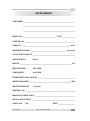
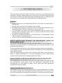
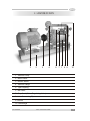
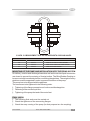
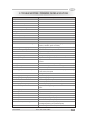
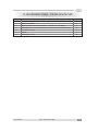
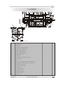
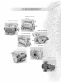
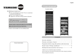
Two Stage
Water Ring Vacuum Pump
VWS II Series
PPIS
PPI SYSTEMS
ISO 9001: 2008 CERTIFIED COMPANY
PPIS
Thank you for purchasing the PPI WATER RING VACUUM PUMP
Before using the pump, please read the operating instructions so you can
easily install, operate and maintain the pump.
This pump or this pump unit, respectively may be mounted and put into
operation by qualified technical personnel only and these operating
instructions and the effective regulations have strictly to be observed. If you
don't pay attention to these operating instructions,
1. Danger may be created for you and your colleagues
2. The pump or the pump unit may be damaged
3. The manufacturer is not liable for damages resulting from this nonobservance!
Please be aware of your responsibility for your fellow men when working at the
pump or the pump unit!
PPI SYSTEMS
VWS-II TWO STAGE PUMPS
PPIS
CONTENTS
DATA SHEET
Page No.
1. SAFETY INSTRUCTIONS/WARNING
1
2. LOCATION OF ITEMS
2
3. ERECTION & INSTALLATION PROCEDURE
3-4
4 .CONNECTION OF VACUUM PUMP
5
5. WORKING INSTRUCTION
6
6. PARTS INFORMATION
7
7. DISASSEMBLY AND ASSEMBLY FOR MAINTENANCE
8-11
8. TROUBLE SHOOTING : PROBLEMS, CAUSES AND SOLUTIONS
12
9. BEFORE YOU CALL SERVICE PERSONNEL
13
10. MATERIAL OF CONSTRUCTION
14
11. LIST OF ACCESSORIES
15
12. RECOMMENDED SPARES
16
y
CROSS-SECTIONAL DRAWING
17
y
GENERAL ARRANGEMENT DRAWING
18
y
RANGE OF OTHER PRODUCT
19
PPI SYSTEMS
VWS-II TWO STAGE PUMPS
PPIS
DATA SHEET
CUSTOMER :____________________________________________________
____________________________________________________
____________________________________________________
MODEL NO. :_________________________________ TYPE:_____________
PUMP SR. NO. :__________________________________________________
3
CAPACITY :________________________________________________ m /hr.
MAXIMUM VACUUM :____________________________________ mm of Hg.
DUTY POINT CAPACITY :__________________________________________.
DRIVE DETAILS :
Direct
MOTOR :____________________________________________________ H.P.
MOTOR SPEED :
1440 RPM
PUMP SPEED :
1440 RPM
FRAME SIZE OF ELE. MOTOR :______________________________________
WATER REQUIRED :_________________________________________ L.P.M.
WATER PRESSURE :
1.0 kg/cm
2
BEARING NO. :_________________________________________________
MANUFACTURING DATE :_________________________________________
INSTALLATION DATE :____________________________________________
COUPLING :
PPI SYSTEMS
Tyre
SIZE :_________________
VWS-II TWO STAGE PUMPS
PPIS
1. SAFETY INSTRUCTION / WARNING
This operating manual gives basic instructions which are to be observed during
installation, operation and maintenance of the pump. It is therefore imperative that
this manual is read by the responsible personnel/operator prior to installation and
commissioning. It is always to be kept available at the installation site.
WARNING
y
y
y
y
y
y
DO NOT CARRY OUT ANY MAINTENANCE WHILE THE PUMP IS CONNECTED TO
THE MOTOR.
NEVER START OR STOP THE PUMP WITHOUT WATER.
NEVER INCREASE HEIGHT OF WATER OUTLET FROM PUMP SILENCER IT WILL
ABSORBS MORE POWER & TRIPPING OF ELECTRIC MOTOR.
IT IS ADVISABLE TO CHECK THE WATER HARDNESS AND, IN CASE OF THIS
EXCEED AND TOLERANCE LIMITS (50 to 150 PPM) A PROPER PURIFICATION
SYSTEM SHOULD BE PROVIDED.
IN CASE OF CALCAREOUS WATER, IT IS NECESSARY TO DISASSEMBLE FROM
TIME TO TIME THE PUMP DESCALE IT.
DO NOT LOOSE OR TIGHTEN BEARING COVER BOTLS WITHOUT ANY INSTRUCTION
SAFETY INSTRUCTIONS RELEVANT FOR MAINTENANCE, INSPECTION
AND ASSEMBLY WORK
Any work on the pump shall only be performed when it is at a standstill. It is
imperative that the procedure for shutting down the machine described in this
manual is to be followed.
Pumps and pump units which convey hazardous media must be decontaminated.
On completion of work all safety and protective facilities must be reinstalled and
made operative again.
Close the isolating valves at pump inlet, outlet and seal water. Let the pump cool
down to ambient temperature if it has been handling hot fluid. Adopt safety
measures if the pump has been handling hazardous fluids.
UNAUTHORIZED ALTERATIONS AND PRODUCTION OF SPARE PARTS
Any modifications may be made to the vacuum pump only after consultations with
the manufacturer. Using spare parts and accessories authorized by the
manufacturer is in the interest of safety. Use of other parts may exempt the
manufacturer from any liability.
UNAUTHORIZED MODE OF OPERATION
The reliability of the vacuum pump delivered will only be guaranteed if it is used in
the manner intended and in accordance with the instructions of this manual. The
limit values specified in the data sheet must under no circumstances be exceeded.
PPI SYSTEMS
VWS-II TWO STAGE PUMPS
1
PPIS
2. LOCATION OF PARTS
3
2
5
4
9 7 1 6 8
10
1. Vacuum Pump
2. Base Frame
3. Electric Motor
4. Vacuum Gange
5. Tyre Coupling
6. Ball valve
7. Stop Cock (Water Regulating Valve)
8. Inter Connecting Pipe
9. Suction
10. Dishcharge
PPI SYSTEMS
VWS-II TWO STAGE PUMPS
2
PPIS
3. ERECTION & INSTALLATION PROCEDURE
PROPER ERECTION IS VERY IMPORTANT FOR SMOOTH RUNNING & LONG
SERVICE OF THE PUMP. (REFER G. A. DWG.)
1. Prepare foundation as per drawing.
2. Generally vacuum pump supplied with Common Base frame for Pump & Motor &
Coupling set. In this case, pump side coupling is supplied duly fitted on pump. You
have to connect motor side coupling on your electric motor.
PROPER FOUNDATION
y Correct foundations and installations are essential to assure a safe operation. A
non compliance with the norms of correct foundation and installation could
cause pump failures.
y The pump must be installed on flat surface, rigid enough to withstand its weight
and suitable to withstand the loads cause by the motor mechanism and by the
pump operation.
y In order to avoid vibration or wear of the coupling, it is necessary to keep a
correct alignment during continuos operation conditions.
MOUNTING OF COUPLING
When assembling pump and motor both shafts must be centrally to each other and
be easily turntable. The distance between both coupling halves shall have the
specified measurement. (ref. Figure. 1 )
TYRE COUPLING
T5 M = 25MM VWS-50&75 TWO STAGE
T6 M=30MM VWS-100 & 150 TWO STAGE
T7 M=42MM VWS-200 & 250 TWO STAGE
PPI SYSTEMS
VWS-II TWO STAGE PUMPS
3
PPIS
3. ERECTION & INSTALLATION PROCEDURE
M
%%UFIG. 5.1 MEASUREMENT TO BE SET BETWEEN BOTH COUPLING HALVES
COUPLING SIZE
T5
T6
T7
M
25 mm
30 mm
42 mm
TYPE COUPLING
USED ON MODEL
VWS-50 & VWS-75 TWO STAGE
VWS-100 & VWS-150 TWO STAGE
VWS-200 TWO STAGE
MOUNTING OF THE PUMP AND INSTALLATION INTO THE PIPING SYSTEM
On delivery, suction and discharge branch as well as the service liquid connection
are closed to prevent the entering of foreign bodies. The Blind Rubber Packing to
be removed only immediately before connecting the pipelines. The weight of heavy
pipelines must be supported in order to prevent distortions of the pump.
The pump has to be aligned with the pipelines.
The screws are to be tightened in the following order:
y Tightening of the flange connections of suction and discharge line
y Fastening of the service liquid line
y Tightening of the pump feet and of the motor feet
FINAL WORK
y The following final work must be carried out
y Check the tightness of the connecting flanges
y Check the easy running of the pump (for that purpose turn the coupling).
PPI SYSTEMS
VWS-II TWO STAGE PUMPS
4
PPIS
4. CONNECTIONS OF VACUUM PUMP
PIPELINES
y Pay attention to the arrows at the pump pipe line indicating the flow direction.
y The nominal widths of the pipelines must not be smaller than the nominal widths
of the corresponding pump branches.
y All pipelines must be cleaned prior to installation of the pump.
y The pipelines must be supported in order to avoid distortions of the pump
components (danger of breaking of the pump components).
y The suction, discharge and service liquid lines must be as short as possible and
their cross-section must be as least as the corresponding pump connections.
For long pipelines larger cross sections are required.
identify first locations and dimensions of all connections required to interconnected
the pump with the installation, then proceed with the actual piping.
SUCTION LINE
A non-return valve should be installed in the suction line. It prevents back flow of
gas and liquid in the suction piping when the pump stopped.
If the pump shall be started-up or stopped with closed shutoff element, e.g. Valve in
the suction line, cavitation occurs, too.
DISCHARGE LINE
The discharge line must not be led more than 1m vertically or diagonally upwards. If
a shutoff element is installed in the discharge line behind the liquid separator, it
must be ensured that the pump cannot be put into operation while this shutoff
element is closed.
SEAL WATER LINE
For a good operation the watering vacuum pumps must be supplied with a seal
water which is clean, non abrasive and of any solids. The service seal water should
not exceed 30.31 degree centigrade and the gas handled should be maximum 90
degree centigrade.
PPI SYSTEMS
VWS-II TWO STAGE PUMPS
5
PPIS
5. WORKING INSTRUCTION
STARTING
1. Turn shaft by hand to ensure that pump runs freely.
2. Start electric motor, see the direction of rotation. It should be clockwise looking
from the coupling side. Never start pump without water, Always start the
water first, then pump.
3. Regulate the quantity of water supply as per pump data sheet by means of plug
or stop cock. Excessive water quantity is also dangerous and may overload the
motor.
4. Check the temperature rise of bearing housing at regular intervals of 15 minutes
during the first two hours of operation.
5. If the temperature does not stabilizes below 65 degree centigrade stop the
pump and investigate the problem.
STOPPING
1. Always stop the pump first and then the water supply.
2. Close the water line ball valve without disturbing the cock valve.
STORAGE
If the pump is required to be storage for long time, drain water completely
by opening two plugs at the bottom of casing cover. Fill the lubrication oil from
suction flange. To avoid rust deposition inside the pump.
PPI SYSTEMS
VWS-II TWO STAGE PUMPS
6
PPIS
6. PARTS INFORMATION
Casing 1st Stage
Casing 2nd Stage
Cover
Rotor 1st Stage
Rotor 2nd Stage
Shaft
C Side Control Plate (NDE)
D Side Control Plate (DE)
C Side Control Plate with
Between Rotor
D Side Control Plate
Between Rotor
Bearing Bracket
Stuffing Box
Lock nut for Rotor
Bearing Cover outer C & D
Bearing Cover inner
Drive / Non Drive End
Bearing
Inter Connection pipe
Tyre Coupling
Mech Seal
Rotor with Shaft
PPI SYSTEMS
VWS-II TWO STAGE PUMPS
7
PPIS
7. DISASSEMBLY & ASSEMBLY FOR MAINTENANCE
BEFORE STARTING THE PUMP DISASSEMBLE ENSURE THE
FOLLOWING THINGS
y When assembly and disassembly the pump especially observe that no toxic or
aggressive media can escape from open lines. Secure the shut off organs
against unauthorized operations.
y Drain the pump before the disassembly out of the plant. After draining, residuals
of liquid will remain in the pump which must be removed by flushing the pump
with a suitable liquid.
y The electrical connections must be fixed or separated respectively only after
removal of the corresponding fuse.
MAINTENANCE
The pump requires only little maintenance. However, the following points must be
observed.
y The bearings shall be lubricated after approximately 10,000 service hours.
y The mechanical seals do not require any maintenance. With normal operation,
leakage's occur only after several 1000 service hours if parts subject to wear
are used up.
y In case of risk of freezing, the pump, the liquid separator and the pipelines are to
be drained if necessary, the pump is to be preserved.
y If the pump is required to be storage for long time, drain water completely by
opening two plugs at the bottom of casing cover. Fill the lubrication oil from
suction flange.
y In case strongly calcareous water is used as service liquid, the pump has to be
opened at least in a period of six months in order to remove the
calcareous(scale) deposits.
y The calcareous deposits can be avoided if the service liquid is prepared with a
suitable agent. The measures to be taken depend on operation time and water
quality.
y In case the pump has not been in operation for a longer period of time, it must be
drained.
DISASSEMBLY
Proceed according to the following order:
y Switch off the power supply
y Disconnect the motor
y Drain the installation within the pump area, i.e. between the slides at suction
and discharge side.
PPI SYSTEMS
VWS-II TWO STAGE PUMPS
8
PPIS
7. DISASSEMBLY & ASSEMBLY FOR MAINTENANCE
y
y
y
y
y
If necessary disconnect measuring probes and control instruments and
dismount them.
Drain liquid out of the pump.
Dismount the pump out of the installation.
If necessary, flush the pump.
Remove coupling half
DISMANTLING OF THE VACUUM PUMP
Please proceed as follows:
y Remove key. Release hex bolt and remove outer bearing covers from drive
side. Remove the hex bolts from the bearing bracket. With the help of bearing
puller remove the bearing safely.
y Unscrew the hex bolt of the stuffing box and remove it. Pull the mechanical seal
out from the shaft.
y Unscrew the nuts and remove the studs from the body. Take off the casing
cover. Remove the casing of the first stage.
y Open the lock nut of the rotor and pull out the rotor from the shaft. Remove the
key of rotor.
y After removing the rotor, take off the two control plates so the second stage
casing can be remove. Remove the second stage casing.
y Remove the spacer between rotor and than second stage rotor. Remove key of
the rotor.
y Repeat the step 1 to remove bearing from the non drive side end.
ASSEMBLY
Preparation for assembly:
y Clean all pump parts carefully. Observe that the sealing have no grooves and
that the guide disc is plane. Possibly the guide disc must be smoothed by
means of abrasive cloth on a leveling plate.
y Coat the running surface of guide disc (except sealing fittings) with Anabond
610 (sealing gasket).
y When mounting no foreign substances and no superfluous sealing mass must
enter the pump.
ASSEMBLY OF THE PUMP
Proceed as follows:
y All marks must be in perfect alignment. If one or several parts are replaced,
which may effect the position of the rotor by their axial length, the rotor must be
PPI SYSTEMS
VWS-II TWO STAGE PUMPS
9
PPIS
7. DISASSEMBLY & ASSEMBLY FOR MAINTENANCE
y
y
y
y
y
y
y
y
y
mounted again. The spacer has to be machined in such a way that the length
becomes about 0.20 mm greater than the width of the control plates when
pressed together and the depth of the recess in impeller.
Press control plates in the centering of the casing and tighten with screws.
Put on the shaft, at the non-driven side, a the lock washer and screw on slightly
the shaft nut. Put key into groove of shaft. Slip rotor on shaft. Adjust a distance
between the chamfer of the shaft and the front surface of the rotor. Put the
second key into the groove of shaft, slip the rotor on to the shaft against control
plates and spacer. Put on slightly the lock washer and fasten it by the lock nuts.
The vanes of both rotor must be inclined to the sense of rotation.
Lay down the pre assembled casing, control disk upward. Center the central
body on the control plate. Insert the pre assembled shaft, drive side upward and
center control plate on to the central body. Center the central body on to the
control plate. Center the pre assembled casing, control disk first, on the central
body. Tighten the tie bolts only manually.
Push on the shaft the spacer and the rotating parts of the mechanical seal.
Observe the correct sense of rotation of pumping screw clockwise. Press
stationary seal ring of mechanical seal in the shaft sealing casing and fasten by
the screws to casing. Pay attention that the cast on the rear side of the shaft seal
casing points toward the casing feet.
Center the bearing bracket on the casing in such a way that the drain opening
points to the casing feet, then tighten by the screws. Press in the cleaned or new
anti friction bearing. Fasten the bearing covers and with the screws to the
bearing bracket.
Turn the pump carefully by 180o so that the drive side points downward. Push
on the shaft the spacer and the rotating parts of the mechanical seals. Observe
the correct sense of rotation of pumping screw clockwise. Press stationary seal
ring of mechanical seal in the shaft sealing casing and fasten by the screws to
casing. Pay attention that the cast on the rear side of the shaft seal casing points
toward the casing feet.
Slip on the shaft the bearing cover and the thrower. Center the bearing bracket
on the casing in such a way that the drain opening points to the casing feet, then
tighten by the screws. Press in the spacer and the cleaned or new anti friction
bearing tighten by the shaft nut and secure by the safety tab washer. Put on the
bearing cover. Screw on slightly the screws for fastening of the bearing cover
and do not tighten.
Put the pump horizontally, align the pump feet on a plane base and tighten
crosswise the tie bolts.
The total play of the rotor is measured by alternating tightening of the bearing
covers and until the rotor stop. When doing the cover in direction of the
PPI SYSTEMS
VWS-II TWO STAGE PUMPS
10
PPIS
7. DISASSEMBLY & ASSEMBLY FOR MAINTENANCE
y
movement has to be completely loosened before. The degree of displacement
can be determined at the shaft end by means of a dial gauge. The rotor
adjustment to the middle of the measured play is also achieved by means of the
bearing covers and by loosening the cover tightened at last and by re-tightening
the counter cover until the dial gauge indicates the correct value. Then tighten
the loosened cover evenly.
Put connecting pipe 1 with sealing on pump branches and tighten with s c r e w s ,
studs and nuts. Insert ruff key in the groove of shaft, put on coupling half and the
pump can now be reinstalled into the system.
TEST WORK
After assembly the following test work has to be carried out:
1. Check the easy running of pump by rotating at the free shaft end. In case the
pump should be stuck, probably the vane-wheel impeller has been wrongly
adjusted. The trouble has to be eliminated.
2. Carry out a hydrostatic pressure test with 4 kg/cm2 (hydraulic test) Drain pump.
3. Carry out a leakage test (with foaming agents).
PPI SYSTEMS
VWS-II TWO STAGE PUMPS
11
PPIS
8. TROUBLE SHOOTING : PROBLEMS, CAUSES & SOLUTIONS
List of possible causes
PROBLEM
Pump does not create or the vacuum is too low
Excessive noise
High Power Consumption
Vibration
Mechanical Seal Leaking
Pump looses liquid
Bearing Failure
Pump does not start
Shaft Partialy or totally locked
Cavitation
1-2-3-4-9-11-18-19-22-23-24-25
1-4-5-6-7-10-24
1-5-6-8-9-15-24-25
5-6-7-8-10-12-13-24
11-24, 5, 6, 14
11-19-23
5-6-7
1-6-20-21
6-10-15-16-21
3-4-8-9-17-24
SR. NO.
1 Defective motor OR wired wrong
CAUSES SOLUTIONS
Check the voltage, the frequency, motor type, power consumption,
rotation, connection, phase consistency
Repair piping, check valves for leakage
Lower the seal water temperatur, check the level of seal water,
adjust the cooling water flow.
Increase the seal water flow
Re-align the coupling and the pump/motor assembly
Replace the bearing
Open the anti-cavitation valve or set the relief valve to a lower
vacuum.
Reduce the seal water flow, adjust the by-pass valve
Check the discharge line for obstructions or high friction losses,
reduce the back pressure to 0.1 bar.
Verify that the base surface is level and that all pump feet are resting
on the surface, add spacer
Change the mechanical seal
Remount the pump
Support the piping with hangers.
Check flushing liquid temperature, flow and pressure
Clean the pump
Disassembly the pump to remove the foreign particles.
Open the vacuum regulating valve and /or the vacuum relief
valve
Reverse the rotation
Replace the defective gasket
Check the electric connections.
Disassemble and repair the pump
Select a pump with higher capacity
Disassemble and repair the pump
Reduce the fliquid flow through the pump suction; install a
centrifugal seperator(cyclone) before the pump
Check working characteristics, replace if required
2
3
Leakage in suction piping
Seal water high temperature
4
5
6
7
Low seal water flow
Coupling misalignment
Faulty bearing
cavitation
8
9
High seal water flow
High back pressure
10 Wrong pump / motor assembly
11
12
13
14
15
16
17
Mechanical seal failure
Wrong pump mounting
Piping weight resting on pump
Inadaquate seal lubrication
Minerals diposits from hard water
Foreign particles in pump
Low suction pressure
18
19
20
21
22
23
24
Wrong pump rotation
Bad gaskets
Wrong motor connections
Pump jamed
Pump undersized
Pump worn-out
Excessive liquid flow through suction line
25 Instrumentation out of calibration
PPI SYSTEMS
VWS-II TWO STAGE PUMPS
12
PPIS
9. BEFORE YOU CALL SERVICE PERSONNEL
y
y
y
READ instruction manual carefully and thoroughly.
ALWAYS start water first and then pump.
NEVER start pump without water.
IF PUMP GOT JAMMED
First fill pump with diesel / kerosene and leave it 24 hours. Most probably pump
will be free. If not then. Check for Mechanical Rubbing or Touching.
IF PUMP DOES NOT DEVELOP SUFFICIENT VACUUM
y Check the vacuum gauge against master gauge.
y Check for back pressure and make sure that discharge line is open to the
atmosphere.
y Check & see that outlet of silencer is not choked.
y Check quantity of water. Make sure it is as per given in manual. Also check inlet
water pressure which should be 1.0 kg/m2 max.
IF PUMP MAKES NOISE
y If rattling continues to be heard at low vacuum, open the pump and check for
entry of foreign particle and also check for broken rotor blade because of that
particles.
y Check the alignment to rotor with the pump and distance between two coupling.
IF YOUR MOTOR IS OVERLOADED
y Check that pump turns free by hand when stationary.
y Check excessive seal water quantity and pressure.
y Check alignment to motor with the pump and distance between two couplings.
y Dismantle pump and check for any internal damages or for scale formation.
Excessive scale formation can effect to the smooth operation of vacuum pump
and overload the motor.
PPI SYSTEMS
VWS-II TWO STAGE PUMPS
13
PPIS
10. MATERIAL OF CONSTRUCTION
COMPONENT
QTY
A
MATERIAL
C
S
CASING (FIRST STAGE)
1
CAST IRON
CAST IRON
SS-304 / SS- 316
CASING (SECOND STAGE)
1
CAST IRON
CAST IRON
SS-304 / SS- 316
CASING COVER
2
CAST IRON
CAST IRON
SS-304 / SS- 316
ROTOR (FIRST STAGE)
1
PH. BRONZE SS-304
SS-304 / SS- 316
SS-304 / SS- 316
ROTOR (SECOND STAGE)
1
PH. BRONZE SS-304
SS-304 / SS- 316
SS-304 / SS- 316
CONTROL DISC (DRIVE SIDE)
1
CAST IRON
SS-304 / SS- 316
SS-304 / SS- 316
CONTROL DISC (CLOSE SIDE)
1
CAST IRON
SS-304 / SS- 316
SS-304 / SS- 316
CONTROL DISC (D-SIDE BET'N
1
CAST IRON
SS-304 / SS- 316
SS-304 / SS- 316
1
CAST IRON
SS-304 / SS- 316
SS-304 / SS- 316
SHAFT
1
EN-8 / SS-316
SS-304 / SS- 316
SS-304 / SS- 316
SPACER(BET'N TWO
1
SS
SS
SS
SINGLE MECH. SEAL
2
CARBON Vs. BUME 5
CARBON Vs. BUME 5
CARBON Vs. BUME 5
STUFFING BOX.
2
CAST IRON
CAST IRON
SS-304 / SS- 316
BEARING SINGLE ROW
2
STD.
STD.
STD.
BEARING BRACKET
2
CAST IRON
CAST IRON
CAST IRON
2
CAST STEEL
CAST STEEL
CAST STEEL
1
CAST IRON
CAST IRON
CAST IRON
1
CAST IRON
CAST IRON
CAST IRON
FIRST AND SECOND ROTOR)
CONTROL DISC(C-SIDE BET'N
FIRST AND SECOND ROTOR)
CONTROL DISC)
DEEP GROOVE BALL
BEARING COVER
(INNER SIDE)
BEARING COVER
(DRIVE SIDE)
BEARING COVER
(NON DRIVE SIDE)
ROTOR NUT FOR
LOCKING ROTOR
2
SS
SS
SS
STUD FOR PUMP
6
MS
MS
SS
1
STD.
STD.
STD.
STD.
STD.
STD.
M12 X 365 LONG (for vws-75II)
M16 X 420 LONG (for vws-100II,
vws-150II, vws-200II)
LOCK NUT
M40 X 1.5, KM 8
LOCKING WASHER I.D.
40 mm X 1.5 mm THK., MB 8
1
SUBJECT TO CHANGE WITHOUT PRIOR NOTICE
PPI SYSTEMS
VWS-II TWO STAGE PUMPS
14
PPIS
11. LIST OF ACCESSORIES
y
y
y
y
y
y
y
Vacuum Gauge - (0 to 760 mm of Hg. direct mounting.)
Coupling Set - (Tyre Coupling)
Ball Valve - (on/off Valve)
Stop cock valve - (water regulating valve)
Common base frame for pump and motor
Matching flange - ( Fitted with pump )
Water strainer - (Brass for water line)
OPTIONAL ACCESSORIES
1. Non return valve
2. Coupling guard
3. Foundation bolt
4. Silencer
Carefully remove the pump from packing cartoon and examine for transportation
damage. Check that all accessories are included, if you fin missing any item
consult to our works.
PPI SYSTEMS
VWS-II TWO STAGE PUMPS
15
PPIS
12. RECOMMENDED SPARES : FOR ONE VACUUM PUMP
SR. NO.
1
2
3
4
5
6
7
PPI SYSTEMS
PART NAME
Gasket Sealant Anabond 610 (50 ml)
Mechanical Seal
Bearing (drive & non drive) 6306 for VWS 50 / 75 Two Stage
Bearing (drive & non drive) 6308 for VWS 100 / 150 / 200 Two Stage
Lock Nut for Rotor
Spacer
Stuffing box cover
VWS-II TWO STAGE PUMPS
QTY.
2
2
2
2
2
1
2
16
PPIS
C. S. DRAWING
5
20 15 14 13
7
2
4
9
8 10
1
3
6
5
13 14
15
VACUUM GAUGE
CONNECTION
12
16
21
17
SUCTION
DISCHARGE
12
WATER DRAIN
WATER DRAIN
11
11
19
22
18
WATER
INLET
CLOCKWISE ROTATION FROM COUPLING END
.
22.
STUD FOR PUMP
6
21.
LOCKING WASHER I.
1
20.
LOCKING NUT
1
19.
SPACER (BET'N TWO CONTROL DISC)
1
18.
ROTOR NUT FOR LOCKING ROTOR
2
17.
BEARING COVER (CLOSE SIDE).
1
16.
BEARING COVER (DRIVE SIDE).
1
15.
BEARING COVER (INNER SIDE) - C S
2
14.
BEARING BRACKET. - C1
2
13.
STUFFING BOX.
2
12.
DEEP GROOVE BALL BEARING SINGLE ROW
2
11.
SINGLE MECH. SEAL
2
10.
SHAFT
1
9.
CONTROL DISC (C-SIDE BET'N FIRST & SECOND ROTOR)
1
8.
CONTROL DISC (D-SIDE BET'N FIRST & SECOND ROTOR)
1
7.
CONTROL DISC (CLOSE DISC)
1
6.
CONTROL DISC (DRIVE SIDE)
1
5.
CASING COVER
2
4.
ROTOR (SECOND STAGE)
1
3.
ROTOR (FIRST STAGE)
1
2.
CASING (SECOND STAGE)
1
1.
CASING (FIRST STAGE)
1
SR. NO.
DESCRIPTION
PPI SYSTEMS
QTY.
VWS-II TWO STAGE PUMPS
17
PPIS
G. A. DRAWING
DISCHARGE FLANGE
SUCTION
FLANGE
WATER INLET
6
PRESSURE
NOTE : 1) ITEM MARKED WITH * IS NOT IN PPI SCOPE.
2) DIRECTION OF ROTATION : CLOCK-WISE
7
11
SUCTION
DISCHARGE
12
8
1
2
3
4
5
A
14
10
G.L.
G.L.
%%uSEC.:`A-A'
G.L.
HARD FOUNDATION
A
12.
STOP COCK (WATER REGULATING VALVE)
1
11.
BALL VALVE (WATER ON/OFF VALVE)
1
10.
BASE FRAME FOR PUMP & MOTOR
1
9.
MATCHING FLANCE
2
8.
VACUUM GAUGE 0-760 mm OF Hg. 4" DIA. DIAL 3/8" BSP
1
7.
TEFC ELE. MOTOR
1
6.
FLEXIBLE TYRE COUPLING
1
5.
SINGLE MECH. SEAL
2
4.
STUFFING BOX
2
3.
CASING COVER
2
2.
CASING SECOND STAGE
1
1.
CASING FIRST STAGE
1
SR. NO.
DESCRIPTION
PPI SYSTEMS
QTY.
VWS-II TWO STAGE PUMPS
18
OUR RANGE OF OTHER PRODUCT
WATER RING VACUUM PUMP
(CONE TYPE)
WATER RING VACUUM PUMP
SINGLE CONE VACUUM PUMP
TWO STAGE VACUUM PUMP
ROOTS BLOWER
CLOSE COUPLE VACUUM PUMP
CHEMICAL PROCESS PUMP
PPIS
PPI SYSTEMS
Green House -A, Phase-1, G.I.D.C. Estate, Vatwa Ahmedabad - 382445. India
Phone
: +91 79 2583 2273 / 2583 2274, 2583 5698 Fax : +91 79 2583 0578
E-Mail
: [email protected]
Website : www.ppipumps.com
BRANCHES SALES OFFICE :
l NEW DELHI : PH : 093129 94234 / 3090 7842
l MUMBAI
l CHENNAI
l HYDERABAD : PH : 098480 38130 / 236160061
l INDORE
l U. P.
: PH : 093801 99659 / 2361126
: PH : 098270 70528 / 593060 / 668
: PH : 093193 93897
l KOLKATA
: PH : 093225 48175 / 2562 5473
: PH : 098304 62669 / 26512483
l BANGALORE : PH : 093798 67883
HARNVEE /07-10/ PH. : 079- 2755 6742
PPIS