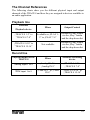
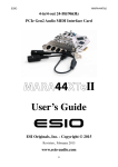
1
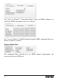
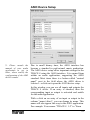
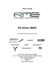
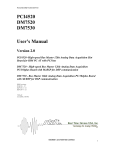
TRACE 8 User’s Guide The Trace 8 conforms the following standards: EN 55022: 1998 + A1: 2000 + A2: 2003; class A EN 55024: 1998 + A1: 2000 + A2: 2003; class A In order for an installation of this product maintain compliance with the limits of a class A device, shielded audio cables must be used, not longer than 50 cm. Attention: This is a device of the class A and can cause interference to radio or television reception within the residential area. The user is encouraged to try to correct the interference by suitable measures. © June 2007, v1.1 MARIAN. Hardware Design by MARIAN All rights reserved. No part of this User's Guide may be reproduced or transmitted in any form or by any means, electronically or mechanically, including photocopy, translation, recording, or any information storage and retrieval system, without permission in writing from MARIAN. All trademarks are the property of the respective owners. MARIAN is not liable for any damage to the software, hardware and data and costs resulting from it, which are caused by improper handling or installation of the hardware. Technical changes are reserved. Table of Contents Welcome 4 Features 6 Installation 7 Scope of Supply 7 System Requirements 7 Installation of Hardware and Software 7 Updating Drivers and Firmware 8 Connectors on the TRACE 8 9 TDM SyncBus 9 The TRACE 8 in Detail 10 The First Contact 10 The Mixer What is it all about? The channels The master channel Adaptable – changing the view of the TRACE 8 Mixer The number of aux sums Further functions 11 11 12 14 15 16 16 The Output Control What is it all about? Adaptable – changing the view of the Output Control 18 19 20 The Clock Status Panel What is it all about? Clock status and sample rate 22 22 22 MIDI Routing 23 Saving and Loading Setups 23 The MARIAN TDM SyncBus Principles of the TDM SyncBus Using the TDM SyncBus 24 24 25 The Settings General Synchronization Latency Audio Options MIDI filter ASIO Device Setup 26 27 28 31 32 33 35 The TRACE 8 in the Connection with Digital Devices Background What is a clock? The rules in the digital audio world Important notes on TRACE 8 and digital clock. 37 37 37 38 38 The Channel References Playback line Record line 41 41 41 PCI Bus Master Technology 42 Hands on the TRACE 8 43 Sounding Good Background How to do it? 43 43 43 Setting up the Latency Background Setting up the “DMA Latency” Setting up the audio driver latency 44 44 45 46 In a Project Studio Situation Hardware routing Software routing Volume settings Finalizing 47 47 47 47 48 48 The TRACE 8 as Hard-Disk-Recording-System Situation What’s there to care about? 49 49 49 The TDM SyncBus – Example 1 The situation The solution 51 51 51 The TDM SyncBus – Example 2 The situation The solution 52 52 52 Glossary 53 Technical Facts 57 Service and Support 59 Warranty 59 Contact 59 Welcome Congratulations and thank you very much for your decision in favor of a MARIAN product. You have chosen a sophisticated and powerful sound system, created according to your needs, the needs of our faithful customers. We are proud to present to you: the TRACE 8. With this fine piece of high technology you are equipped perfectly for the challenges of digital audio signal processing - today and in the future. That is because the TRACE 8 is not just simply a recording system with professional connections in crystal-clear audio quality of 24 bit and 192 kHz – once installed it will upgrade your computer to a most flexible digital audio workstation. It finally offers you all the possibilities for your studio which had yet been realized with expensive additional equipment only and hardly ever within a computer. You can, e.g. mix playback signals of a software and input signals on the TRACE 8 on a comfortable mixer surface without any delay. Thanks to the unique Output Control extensive routings of all available signals and mix-signals are set up, saved and recalled in a jiffy – just like at a patchbay. High-Quality recordings, professional workflow with headphone mixes, reverb sends and even most complex signal routings – with the TRACE 8 from today on, this will be an easy task for you! As the special feature, the TRACE 8 includes the all-new TDM SyncBus. This amazing and mighty tool of digital signal processing is integrated directly within the powerful DSP mixer. With the help of the TDM SyncBus all available signals can easily be directed to the input of a TRACE 8 or other Marian Soundcards with TDM SyncBus option, and are available there like “real” physical input signals. The resulting routing- and mixing-capabilities are virtually unlimited. Please take your time to go through the next pages of this manual also. Besides helpful explanations for the installation, it offers many valuable hints on how to use the Mixer and the Output Control effectively and profitably. If you run in on technical terms while reading, which are unknown to you, the glossary at the end of this manual will helpfully serve you for their clearance. 4 Now, we do wish you lots of success in working with the TRACE 8. We hope it will bring you just as much fun, as we had developing it. Your MARIAN Team 5 Features Your TRACE 8 ships with a lot of great functions. Here you can find a small list of properties and capabilities. PCI Busmaster card full duplex support 8 analog, balanced in- and outputs 1 MIDI input 3 MIDI outputs 24 channel DSP Mixer; hardware-based; latency-free Flexible and extensive mix-, monitor- and routing possibilities Hardware Routing for MIDI-channels MARIAN SyncBus compatible Optional WordClock input with software switch able termination Synchronization as clock master (output of internal clock SyncBus) Synchronization as clock slave (using external clock on WordClock input or SyncBus) 9 Fail-safe Firmware update technology (automatic recovery of firmware) 9 highly-developed multi-client driver for Windows™ 2000/XP/2003 Server/Vista each in the 32-Bit Version 9 MME, ASIO 2.0, GSIF 2.0, WDM-Audio, DirectSound 9 9 9 9 9 9 9 9 9 9 9 9 6 Installation Scope of Supply After opening the package of the TRACE 8, please check if the following components are included and undamaged. 9 9 9 9 9 9 1 x TRACE 8 PCI slot card 1 x Audio connection cable 1 x MIDI connection cable 1 x CD-ROM with driver software 1 x CD-ROM with bundle software this manual with quick installation guide System Requirements For successful and orderly operation of the TRACE 8, the following basic requirements have to be met. Intel Pentium-, or AMD CPU with at least 1 GHz clock and 256 MB RAM 9 Operating system Windows™ 2000/XP/2003 Server/Vista each in the 32-Bit Version 9 Direct X 9c 9 One free PCI slot 9 Please note that depending on the operating system and audio application used, the system requirements might increase. Installation of Hardware and Software On the quick start guide and in the interactive tutorial on the driver CD you will find all important installation steps explained graphically. If you have any further questions concerning the installation, please contact our support service. At the end of this manual you will find the different ways of contacting us. 7 Updating Drivers and Firmware Sometimes we offer a driver update for the TRACE 8 in the download area of the MARIAN homepage. This may include: - functional improvements of the driver and/or the manager - adjustments to new operating systems and/or their new components (updates and service packs) - improvements of compatibility towards other audio applications In case of a driver update, please follow the instructions of the “readme.htm” file. This file is included in the packed folder of the new driver files. Important: Along with a driver update it might be necessary to update the firmware of the TRACE 8. It can only be determined after the installation of the new driver if a firmware update is needed. If that is the case, the update will then be performed automatically and will have to be finished with a restart of the PC-system. The MARIAN fail-safe firmware update technology will prevent the TRACE 8 of errors resulting from an interruption of the update process caused by e.g. a power disruption. Would this usually lead to a complete unavailability of the soundcard, the fail-safe technology now takes care, that with the next initialization of the TRACE 8 a root firmware is loaded, ensuring correct recognition of the soundcard by the Windows™ system. Please note: Subsequently to a successful firmware update, Microsoft Windows™ 2000/XP/2003 Server/Vista will find a new hardware after reboot, since the hardware ID of the TRACE 8 will have changed due to the firmware update. Since the driver files have already been installed, you only need to choose “install software automatically” in the appearing windows hardware wizard. 8 Connectors on the TRACE 8 TDM SyncBus WordClock/ SuperClock input Connector breakout cable for MIDI inputs and outputs Connector breakout cable for audio inputs and outputs TDM SyncBus If other MARIAN sound systems with TDM SyncBus option are installed, they may be connected here using a TDM SyncBus cable. Other MARIAN sound systems with SyncBus option only, can be connected using an adapter cable. Both cables can be ordered at the MARIAN web shop. 9 The TRACE 8 in Detail The First Contact After the successful installation the symbol of the TRACE 8 manager will appear in the Windows™ taskbar of your computer. It offers direct access to important driver settings, the clock status display, the DSP-based 24 channel Mixer and the Output Control of the TRACE 8. Furthermore, you can save and load the setups for Mixer and Output Control and define a MIDI routing. “Info” shows the current driver version of the TRACE 8. This is needed when consulting our support service with certain questions. The menu is opened with a single mouse click, with another on the corresponding entry the window of it is being opened. Via clicking the option “Always on Top” it is prevented that any other window is allowed to cover the Mixer or the Output Control. This option is helpful, when working simultaneous with other windows, while wanting constant direct access on Mixer and Output Control. 10 Z If several TRACE 8 have been installed, the entries for Mixer and Output Control will appear accordingly with the extension „#2“, „#3“ and so on. The settings of the sound systems are managed via one window. The Mixer What is it all about? This window shows all input channels and the master section of the TRACE 8 Mixer. You can see the analog inputs on the TRACE 8 (Analog 1 to 8), the channels of the TDM SyncBus (TDM In 1 to 8) and the playback channels of an audio application (Play 1 to 8). The TRACE 8 offers any application 16 playback channels as devices “Play 1-2” to “1516”. Within the mixer though, only Play 1 to 8 are shown as separate input channel strips. The Mixer treats all shown types of channels equally. 11 The channels All channel strips may be operated in mono- or stereo configuration. The stereo-mode connects 2 channels each to stereo couple. (e.g. 1+2 or 5+6) You may switch the mode via the stereobutton at the lower end of each channel pair. As an example for all types of channels, let’s take a look at input channel “1” from top to bottom. First we have the “GAIN”-knob. It is for adjusting the audio level. For the analog inputs the level adjustment takes place directly at the input stage before the A/D converter of the TRACE 8. This influences the level with which a software application is recording from this input. That is why the “GAIN” knob of the analog inputs is pictured in a different color. For the TDM inputs, “GAIN” will only affect the level of a signal within the mixer. Beneath “GAIN”, “AUX 1”, “AUX 2” and so on are placed. Pulling up knob “AUX 1” will result in a volume increase of the signal in the signal sum aux 1, pulling up knob “AUX 2” increases the volume of the signal in signal sum aux 2 and so forth. Hence the aux knobs have the same function like the fader at the end of the channel, except: not for the master sum, but for each aux signal sum. Besides the aux knobs the “PRE”-button is located. If it is activated with a mouse click, the fader at the end of the channel looses its influence on the corresponding aux knob. Thus, the fader can, for example, be placed on position “-60” while still a signal reaches the Output Control of the TRACE 8 via the affected aux knob. Between “AUX 1” and “AUX 2” as well as “AUX 3” and “AUX 4” and so on a linkbutton is situated. If clicked on, aux volume and pre buttons for aux 1 and 2, aux 3 and 4 and so on are connected functionally. That means: when 12 Z Instructions on how to monitor these aux sums on the TRACE 8, you will find in section “The Output Control”. Z Examples on how to use pre buttons and aux sums correctly please refer to the “hands on”part. Z The number of shown aux controls depends on the operation mode of the TRACE 8! Z If you set up different volumes for “AUX 1” and “AUX 2” without the link-button activated, this relation remains with the link-button pushed. opening up “AUX 1”, “AUX 2” is equally pulled up. Just like that, “PRE”-button of “AUX 2” is activated when pushing “PRE”-button of “AUX 1”. Z The solo button has no influence on the aux sums! If the “Solo”-button is active in one or more channels, the mix out of the TRACE 8 provides the signal of these channels only. Now the knob “BAL” follows. For monophonic channels it sets up the position of a signal between left and right side on the master sum. For stereo channels it regulates the volume relation between left and right channel of the signal. If the “Mute”-button is active in one or more channels, the mix out of the TRACE 8 and the affected aux sums do not carry these signals. The aux busses of these channels are not muted if their “PRE”-button is active. With the help of the fader at the end of the channel strip, the portion of volume of the channel on the master sum is regulated. Next to it, the level meter with clipping LED (up) and “PRE”-button (down) are located. Z Double clicking the field next to the Pre button allows you to enter volumes numerically in dB values. The clipping LED shows a signal clipping before the A/D converter. That means, you can check here, if an input signal overdrives the input stage of the TRAGE 8 before the converter. If “PRE” is active, the level of a digital signal is shown before the gain knob – the level of an analog input channel is shown after the gain but before the fader. If “PRE” is not active, it is measured and shown “post” – that means after the fader. 13 This ends our little overview of the input channels of the TRACE 8 Mixer. Now, you know how to set up the volume of a channel on the master sum or the aux sums. The only thing that’s missing is a possibility to control the level of all of these sum signals. That’s what the master channel on the right side of the Mixer is all about. The master channel The upper knobs regulate the volume of the aux sums. Between “AUX 1” and “AUX 2” as well as “AUX 3” and “AUX 4” and so forth a linkbutton is situated. If clicked on, the concerning Aux-knobs are connected functionally. That means: when opening up “AUX 1”, “AUX 2” is equally pulled up. If the Solo-button has been switched on in any channel, the master channel will indicate this with a lit “Solo” LED. Using the “X”-button next to “Solo” you can deactivate all solo buttons of all channels simultaneously. The master faders serve as regulators for the volume of the main sum. They are assigned either to the left or the right channel. As long as the link-button is pushed, they are moved synchronously. 14 Z If you set up different volumes for “AUX 1” and “AUX 2” or the right and the left fader without the link-button activated, this relation remains with the link-button pushed. Adaptable – changing the view of the TRACE 8 Mixer In the bottom left corner of the Mixer you can find three buttons: “Analog”, “TDM” and “PLAY”. These allow, with a click on the button, to hide or show the affected channels. In order to adjust the look of the Mixer according to your needs, single rows of control elements may be hid or shown with the help of “Parts”. This applies to all gain-, aux- or bal knobs. Z Note: Hidden channels are still active, just like they were shown. All these functions can be very handy for saving precious space on your computer screen. But they’re also useful if you wish to secure certain setups of faders or knobs from accidentally being changed. Of course, apart from all these functions, the window can be sized horizontally. If multiple TRACE 8 have been installed, you can bring up the Mixer of every sound system using the drop-down list in the top bar of the window. The lock-symbol in the upper right corner of the window prevents coverage by other windows. This way the Mixer is always on top and accessible. Z Snapshots are independent of setups (see chapter “Saving and loading Setups”). Thus, they will not be overwritten by a setup. You may save certain visual configurations along with the current mixer settings in a “snapshot”. For this, click on one of the three buttons beneath “snaps” on the row “save”. If you wish to recall a snapshot, click on the “load”-button situated beneath the previously saved snapshot. 15 The number of aux sums The TRACE 8 can be operated in 3 different modes. Depending on the mode, only a limited number of aux-sums will be available. On sample rates up to 48 kHz 6 aux-sums will be available. On 96 kHz there will be 2 aux-sums. On 192 kHz, no aux-sum will be available. That’s why the drop-down list of Mixer and Output Control will be automatically adjusted accordingly. Further functions In the lower left corner of the Mixer two function buttons can be found. Via “Setup” the same context menu is opened as when clicking on the TRACE 8 symbol in the task bar. Here you will find fast access to important functions and windows of the TRACE 8 sound system. “Outputs” opens the Output Control. There again you can quickly switch to the mixer surface using the “Mixer” button. 16 Z In section “The TRACE 8 settings” you get to know, how to switch between the modes and what the outcome will be. 17 The Output Control So far, we have taken a look at signals, which either entered the TRACE 8 via a physical input or as a playback signal of a software. The Output Control allows controlling all signals, leaving the TRACE 8. It is opened with single click on “Output Control” via e.g. the TRACE 8 symbol on the Windows™ taskbar. You probably figure, that this window looks pretty much like the Mixer window. Save it doesn’t have gain-, aux and bal knobs but it has routing buttons instead. 18 What is it all about? Z Just like aux- and master-sums the play channels 9-17 are audible on the output of the TRACE 8, only when assigned in the Output Control! This window shows the analog outputs as well as the four TDM outputs of the TRACE 8 as stereo channel strips with the name “Analog OUT”, and “TDM OUT”. Z Aux 1 and aux 2, aux 3 This Example shows how to do it: you wish to monitor the sum “AUX 1-2” at the analog output 1-2 of the TRACE 8. Thus, push the “AUX 1-2” knob in the output channel with the title “Analog OUT 1-2”. That’s easy - isn’t it? and aux 4 and so on are grouped to stereocouples. Z The routing of input signals of the TRACE 8 takes place directly within the hardware of the soundcard and is thereby latency-free. In the Output Control the signals of the TRACE 8 can be routed completely free to an available output or a TDM Bus channel. This applies to any analog input signal, any TDM input signal, any play signal and all stereo aux-sums. The same works for input signals. Example: you wish to route the signal of the input 3-4 of the TRACE 8 to the output 7-8? – No problem. Just push the “Input”-knob on the channel strip “Analog OUT 7-8”. In the drop-down menu below “Input” choose “Analog IN 3-4”. DONE! For a playback signal of an audio application push “Play” in the appropriate output channel strip. After that, choose the desired channel in the drop-down menu. If you choose a signal for an output channel under “SOURCE” you may adjust its volume with the fader at the bottom of that channel strip. The “Mute”-, “PRE”- and link-buttons as well as the level meter and clipping indicator work just the same way as you learned from the Mixer. 19 TDM channels become active with a click on the “ON”-button. If two or more TDM-capable cards have been installed in a computer system, an “ON”-button for a TDM channel may be activated in one Output Control only. If a TDM channel is already active on one soundcard and you try to activate the same channel on another soundcard, an error message will appear. Z For details on the TDM Bus, please read section “The TRACE 8 TDM SyncBus Adaptable – changing the view of the Output Control Similar to the Mixer, there are two buttons: “Analog” and “TDM” in the bottom left corner of the Output Control. With click on the button the channels of this type can be either hid or shown. Furthermore, you may hide or display the routing of the Output Control via “parts”. Z Important on this one: Those channels are not deactivated but simply visually faded out! If multiple TRACE 8 have been installed, you can bring up the Output Control of every sound system using the drop-down list in the top bar of the window. The lock-symbol in the upper right corner of the window prevents coverage by other windows. This way the Output Control is always on top and accessible. You may save certain visual configurations along with the current Output Control settings in a “snapshot”. For this, click on one of the three buttons beneath “snaps” on the row “save”. If you wish to recall a snapshot, click on the “load”-button situated beneath the previously saved snapshot. Z Snapshots are independent of setups (see chapter “Saving and loading Setups”). Thus, they will not be overwritten by a setup. Now you should have gained an extensive overview for your daily work with the two most important windows of the TRACE 8 manager. For indepth comprehension we recommend you to read the articles of the “hands on” part, which are of interest to you. 20 21 The Clock Status Panel What is it all about? The TRACE 8 clock status panel quickly reports sample rates and clock sources of every installed TRACE 8. If multiple TRACE 8 have been installed, you can bring up the states panel of every sound system using the drop-down list in the top bar of the window. The lock-symbol in the upper right corner of the window prevents coverage by other windows. This way the status panel is always on top and accessible. Clock status and sample rate The first row of the panel tells you, which sample rate is captured on which connector or input (WordClock; SyncBus) or is set up for the internal clock. The green LED on each left side, shows, whether or not the clock has been derived correctly from the corresponding input. If no clock source was detected on a connector, the red LED lights up. Additionally the hint “error” shows up. If this input has been chosen clock source in the settings of the TRACE 8, the corresponding column will appear red. The input actually used as clock source will be marked whitely. 22 Z Settings for clock source are handled in the settings window of the TRACE 8 manager. When using the ASIO interface they are done via the software application. Z If the option “Card is SyncBus master” is active, the column “SyncBus” will show an “M” for “Master”. MIDI Routing The TRACE 8 features a routing function for MIDI signals. This allows for MIDI input signals to be sent directly to one or several MIDI outputs of the soundcard. Due to the hardware implementation this happens thunder-fast and without any further software needed. This is how you do it: For every installed TRACE 8 the manager includes a “MIDI Route” row in the menu. By setting the hook in the submenu you can decide, which MIDI output shall carry the signals of the MIDI input. Saving and Loading Setups Z Choose very clear and direct names for your setups, e.g. the date of a session like “recording 2006-11-01”. Also memorize this location well, so you will find this setup quickly next time you need it. Z For quick and separate saving of certain settings of the Mixer or the Output Control, snapshots are a good tool! Within the TRACE 8 manager the options “Save Setup…” and “Load Setup…” can be found. With those you can save all current settings (the setup) of the TRACE 8 Mixer and the Output Control into one single file and recall it when needed. Clicking “Save Setup…” opens the Windows™ file browser where location and file name of a setup are to be assigned. You can save many, many different setups… Clicking on “Load Setup…” opens the Windows™ file browser, where the location of an already saved setup is to be selected. If a file is chosen, clicking “open” will delete all current settings of Mixer and Output Control and overwrite them with the settings of the new setup file. 23 The MARIAN TDM SyncBus Principles of the TDM SyncBus The TDM SyncBus is a collective transport bus for digital audio- and synchronization signals. With the help of the TDM SyncBus all signals of an audio system featuring the TDM SyncBus may be send out to other Marian sound cards with TDM SyncBus or returned to an audio application again. The principle of operation of the TDM SyncBus may be compared quite well with the pneumatic dispatch or tube system within one or between several office buildings. Imagine this: Ms. Smith, from the press department sends out a press report on channel 1 of the tube system. It arrives at the distribution central. If Mr. Mayer from the financial department wishes to read the report, he needs to call for it at the central. He will then receive it in the inbox of channel 1. The same way as Ms. Smith uses a tube channel to send out a document within the building, you can use a TDM channel to send out a signal to the TDM SyncBus via the Output Control. The same way as Mr. Mayer receives the document in the inbox, the audio signal of the TDM SyncBus lands up in the input of the TRACE 8 Mixer and as recording signal. This is also possible: Mr. Miller from the neighboring building may also request the message of Ms. Smith. For this, the distribution central simply copies the document and sends it out a second time to Mr. Miller. That means: If several MARIAN sound cards with TDM SyncBus are installed in a computer, the signals of the TDM channel are available to all the other sound cards as well. BUT: The capacities of the pneumatic dispatch are limited. E.g. if Mr. Miller from the neighboring building also wishes to send a document, he must not use channel 1, since Ms. Smith from the press department is already sending out her stuff here. All in all there are 8 channels, that’s why Mr. Miller must decide for channel 2 to 8. For the TDM SyncBus this means: only one signal in one channel but eight channels at the maximum can be distributed simultaneously. That’s another way to say that a certain TDM channel may only be active in once Output Control. 24 Using the TDM SyncBus As already described, the TRACE 8 offers 8 stereo playback channels. These can be used with one or more software applications. Where these signals are actually played back or where they are send to is completely up to you. E.g. in order to send the playback signal of a software to the TDM SyncBus, all you need to do is to push “Play” of the desired TDM channel (1 to ) in the Output Control and choose the playback signal from the drop down list. By activating the “ON” button, this input signal will be available in the TRACE 8 mixer in every connected MARIAN soundcard with TDM SyncBus option. In order to record the signal of this TDM channel, you need to choose the input “TRACE 8 9-10” in the software application, whereas “TRACE 8 910” to “TRACE 8 15-16” correspond to the stereo TDM channels “1” to “4”. For using the TDM SyncBus please note the necessary settings as described in the section “The TRACE 8 as SyncBus master”. 25 The Settings The following chapter is all about the system settings of the TRACE 8. You open the corresponding window via the TRACE 8 symbol on the taskbar. Should questions remain, we recommend taking a look at the “hands on”part of this manual. Especially the section “The TRACE 8 in connection with digital devices” contains simple examples for right handling of the clock settings. 26 General Operation Mode The TRACE 8 can be operated in three modes. By choosing one of these options, you define which maximum sample rate the TRACE 8 can be operated with. This also affects the number of aux-sums available besides the master-sum. In 192 kHz Mode no additional mixing sum besides the master sum is available. Therefore, in this mode, the mixer and the Output Control do not offer any aux knobs or buttons. When choosing the option “Sample rate up to 48 kHz” there will be 6 aux-sums available. When choosing the option “Sample rate up to 96 kHz” there will be 2 aux-sums available. WordClock Input Signal The optional WordClock/SuperClock input can be operated in different modes. Each option will be a certain relation of the input frequency to the desired samplerate. If you operate the TRACE 8 as last unit in a word clock chain, you can set the termination for the WordClock input right here. Idle Sample Rate In the section “this sample rate”, you can type in, which sample rate the TRACE 8 shall work with, if it is not busy with playing back or recording tasks of an audio application. For example, if you use the TRACE 8 purely as a digital mixer. By choosing “last used rate”, the sample rate, which was used last by a recording or a playback through a software, is kept by the TRACE 8. 27 Synchronization When working with digital audio signals, a clock is always required. The settings listed here, define where this clock comes from. If no clock is available or a wrong clock setting is made, playback errors or even system malfunction can be the result. The TRACE 8 can be operated in 3 different clock modes. The following section will explain these and sort the different options of clock sources accordingly. The TRACE 8 as clock master If “Internal Clock” is chosen, the TRACE 8 itself generates the clock. The TRACE 8 as clock slave If one of the following two options is chosen, the TRACE 8 will work synchronously to connected digital devices and therefore turn into a clock slave. When choosing “WC/SC Input” the clock is caught from the optional WordClock input (if connected). When choosing “SyncBus Clock” the clock from the SyncBus connector on the TRACE 8 is used. For this to work, the option “Card is SyncBus Master” must not be chosen. The TRACE 8 as SyncBus master If you own two or more MARIAN PCI sound systems and have connected them all in your computer using a SyncBus cable, you can now define, which card supplies the digital clock in this setup using the option “Card is SyncBus Master”. On the SyncBus Master card any clock source may be chosen. All other MARIAN PCI sound systems are running synchronously to this clock if their clock source has been set to “SyncBus”. 28 MME/DirectSound Clock Source By selecting “choose automatically” the TRACE 8 driver will search automatically for a valid clock. In most cases, this will be the “internal clock”. Please pay attention to the specialties dealt with in chapter “Important notes on TRACE 8 and digital clock”. Important: The clock settings of the TRACE 8 manager will be ignored and overwritten if an audio application accesses the card via the ASIO driver. The settings will be done by this application. Commonly there is a drop down list showing all available clock sources of the TRACE 8 besides the field where the “ASIO TRACE 8” driver is chosen. After quitting the ASIO application the clock settings of the TRACE 8 manager will be restored. ASIO For most audio applications using the ASIO interface, the clock source for the TRACE 8 may be chosen directly in the application. But some applications do not support this. This is why the TRACE 8 Manager allows with “Initial clock source” to set up a certain clock source in the drop down list, which will be used after the start of such application. With respect on the multi-client capabilities of the TRACE 8 it is not possible to change the clock source for running ASIO applications here. GigaStudio This section is available only if a Tascam GigaStudio application is installed. In the drop-down list, “Clock Source” you can define, to which clock signal GigaStudio is to be synchronously operated to. 29 Classic MME - Start/Stop Sync The start/stop synchronization can be turned on or off for all audio devices. If this option is active, the audio data transfer of all audio devices is started and stopped simultaneously. What effect does that have? Let’s suppose you wish to play back two stereo audio tracks from an audio application on different devices of the TRACE 8 (“TRACE 8 1-2” to “TRACE 8 3-4”). If all devices would be started and stopped asynchronously, it could happen, that track one (here: “TRACE 8 1-2”) starts first with playing back, and track two (here: “TRACE 8 3-4”) starts last with playing back. This offset can distinctively be hearable. But if you choose “synchronous start/stop” the playback start of all tracks will start sample precise. There is no offset between (“TRACE 8 1-2” to “TRACE 8 3-4”. The same applies in a recording situation. This option is only relevant, when working with “classical” MME drivers. In case of ASIO or GSIF, the synchronization is automatically ensured. For WDM/DirectSound the start/stop synchronization is, according to the specifications, not possible. This function is not available for Windows™ Vista 30 Latency DMA Buffer Size Z The DMA buffer size is always simultaneously changing the latency for the GSIF interface. Via the upper slider you can adjust the minimal latency of the TRACE 8. Here, the size of the buffer, shown in samples, is changed for the audio transport between PCI bridge and TRACE 8. If you operate the soundcard with e.g. 44.1 kHz, 88 samples will result in a latency of around 2 ms. On 88,2 kHz, this number of samples would mean a latency of 1 ms. The cart “resulting latency” shows these connections for some important standard sample rates. Z Important hints on how to set up the latency you will find in the „hands-on“-part and section “DMA bus master technology”. By activating “Play test tone at TRACE 8 1-2” a sine tone is played back at the output 1-2 on the TRACE 8 with –6dbfs. Monitor this signal and adjust the value for the DMA buffer to be as small as possible, but without receiving distortions when playing back the sine wave. Z When using the ASIO interface, the DMA buffer size is set up with the ASIO buffer size in the ASIO device setup. 31 Audio Options Classical MME Drivers On Windows™ XP, the MME drivers are run via WDM. This may result in certain disadvantages. By activating this option, all inputs and outputs of the TRACE 8 can be used via the “classical” MME interface. They appear with the suffix “(MME)” on recording and playback devices within an audio application. Please quit all audio applications prior to activating this option. This function is not available for Windows™ Vista. Clock/Sample rate/Device Conflicts As you can see in chapter ”Important notes on TRACE 8 and digital clock”, situations can occur, where certain requirements to the TRACE 8 can not be met. For example: Using the classical MME drivers and encountering a situation, which can not be established, the driver of the TRACE 8 will inform you about this with an appropriate error message or warning. Oftentimes, this can be insufficient since some applications test all available devices of the TRACE 8 on system startup. This test, would certainly lead to an accumulation of such messages. You’d be busy for quite a while confirming these messages by clicking “OK”. By default, error- and warning messages are therefore deactivated. For diagnostic purposes it is recommended to deactivate this option, since it can provide a good hint on searching causes for problems in this direction. This function is not available for Windows™ Vista. 32 MIDI filter This section gives you many options to optimize and adjust the MIDI inputs and outputs of the TRACE 8. Those features are usually found in pretty complex audio applications only. Device Choose the MIDI input or output which you would like to edit. “MIDI Stream Optimizing active” filters unneeded data out of the transmitted MIDI data. You get shorter processing times of the MIDI signals, but without loosing a single MIDI command. “Filters active” enables all configured MIDI filter options. For most comfortable editing, you can change the look of the section “command filters”. There are 3 viewing modes available: On “View by Command”, “Command Filters” shows the MIDI commands, which can now be filtered for each single channel. By clicking “On” or “Off”, the chosen MIDI command is filtered or passed through on all channels. 33 On “View by Channel”, “Command Filters” shows all MIDI channels, on which the MIDI commands can now be filtered. On “View by Matrix” all MIDI channels and the MIDI command filters are shown in form of a matrix. System Data Filter The command filters offered here are MIDI channel independent, but concern the chosen MIDI port. 34 ASIO Device Setup Z Please consult the manual of your audio application to get to know, where exactly the configuration of the ASIO driver is made. Due to small latency time, the ASIO interface has become a standard in professional music production. The ASIO device setup offers important settings for the TRACE 8 using the ASIO interface. It is opened from within an audio application, supporting the ASIO standard. Most times there is a button called “control panel” next to the field where the ASIO driver is selected – a click on it opens the ASIO device setup. In this window you can see all inputs and outputs the TRACE 8 offers. If an entry is checked, then the corresponding input or output is activated and usable for the audio application. With a click on an entry of an input or output in the column “name (alias)”, you can change its name. This name will also appear this way in the ASIO application. For example: You rename “TRACE 8 1-2” to “From 35 Mic Preamp”. Now in the audio software you can see at first glance, which signal origins from the Mic Preamp. In the bottom left corner of the window, the “Execution priority”-slider is situated. It can be dragged between “high” and “low”. In position “high” the transfer of the audio data between ASIO audio application and TRACE 8 receives the highest priority. That means the CPU of the computer processes them preferably. In position “low” the calculation of plug-in effects is given the highest priority, the audio data transfer is cared about secondarily. In the bottom right corner of the window, the “Buffersize in samples”-field is situated. This value defines the delay time (latency) of the audio data transfer for ASIO. Example: When working with a sample rate of 44.1 kHz, a buffer size of 176 samples will give you a delay time of 4 ms. Working with a sample rate of 88.2 kHz, 176 samples will give 2 ms delay. 36 Z Hint: some audio applications require additional steps of activation, so the inputs or outputs of the TRACE 8 can actually be used. For further details, please take a look at the manual of the audio application. Z Changing the “Execution Priority” and the ASIO “Buffersize” might be helpful when encountering distortion noise such as digital errors while playing back or recording. Please read chapter “Setting up the Latency” in the “handson” -part The TRACE 8 in the Connection with Digital Devices Background As you probably already know, there is one big difference between analog and digital audio signals: analog audio signals are continuous. That means at any given time you can measure this signal and retrieve a defined measuring value. As opposed to digital audio signals. They consist of many single values (samples), which follow each other in a certain frequency (sample rate). Here it is not possible to receive a measuring value at any time, but only as often as the sample rate defines. Example: having a sample rate returning one value a second, you can’t measure a value at half a second. What is a clock? As you can see, there has to be something governing, at which moment of time a digital value is to be measured. This is exactly the task of the clock. It is the impulse- or rate generator. The rate, given by the clock, defines the sample rate. Let’s make this a little clearer with an example: Imagine an orchestra with a conductor. The maestro lifts and lowers the baton – he gives the beat. Depending on the beat, the musicians play either fast or slow. The conductor is thereby the clock and the speed the orchestra plays with, that is the sample rate. What happens if an orchestra plays without a conductor? – complete chaos! Every musician plays just like he wants in a different speed. The same happens if you connect digital audio devices. Just like in the orchestra example, there has to be defined, who is maestro (the master) and who are the musicians (the slaves). 37 The rules in the digital audio world Connecting digital audio devices the following three simple rules have to be maintained. 1. All devices have to be synchronized with each other. (Using the clock) 2. There can only be one! That is the device (the master) governing the rate. All other devices have to lock in on this rate (the clock) of the master and are thereby slaves. 3. Digital audio connections mostly include a clock. (S/PDIF; ADAT or AES/EBU). Besides that, the synchronization can be ensured using WordClock- or SuperClock connections. But within a compound of digital audio devices, the clock has to be the same – everywhere. Important notes on TRACE 8 and digital clock. Clock settings when using ASIO If you work with an audio application using the ASIO interface of the TRACE 8, all clock settings will be managed by that program and overwrite the current settings in the manager! Which clock source is used, can still be read in the clock settings within the TRACE 8 manager. The manual of the application should give you report about which clock source the audio application chooses under which circumstance. If the audio application is closed (communication with the ASIO driver is terminated), all previous clock settings are being reset. Level metering in the TRACE 8 Mixer In order for the TRACE 8 Mixer to show the levels of a digital input signal (the TDM channels), it has to use the clock of this input. That means: If the clock source is not read from this input, no digital input signal can be used or shown. In that case, the affected input channel will have a small red square in the level meter. 38 Samplerate on record/playback Please note, that a certain samplerate for the TRACE 8 can only be set, if the used clock source is the internal clock. If synchronized externally (Clock is being read from WordClock input or from SyncBus), the samplerate will be defined by the connected devices. Windows™ Vista only: On Windows™ Vista a certain samplerate is no longer reported to the sound card, if the audio application is not using the ASIO interface or WSAPI. The samplerate set up in the advanced settings of an audio device in the windows control panel is used instead. This leads to the following: 1. If the desired samplerate of an audio application is not equal to the current samplerate, a samplerate conversion with possibly an audible loss of quality will be the result! 2. When using an audio device of the soundsystem with the samplreate x and additionally attempting to use another device but with a samplerate y, an error message will appears, since the soundcard may only be used with one samplerate at a time. In this case no resampling (rate conversion) is undertaken! 3. In order to operate several devices with a certain samplerate, this samplerate has to be set up in the advanced settings of an audio device in the windows control panel for each device separately. As concluded from 2 – no device of the soundsystem should be in use, or else a change will be rejected! 39 Different sample rates on record/playback You already work with certain inputs or outputs of the TRACE 8 with a certain sample rate. Now you wish to use other inputs or outputs simultaneously, but with another sample rate. Since the TRACE 8 can be operated with one sample rate, only, the driver will inhibit the usage of the additional inputs or outputs. The simultaneous operation of the TRACE 8 with different sample rates is possible using the standard-MME or DirectSound driver only. Simultaneous playback on one channel Example: You are playing back on a certain device (e.g. “TRACE 8 1-2”) of the TRACE 8. Now you wish to playback another signal of another software application via the same device. The TRACE 8 driver will inhibit this, except if the simultaneous playback of several audio programs via the same device happens using the standard-MME or DirectSound drivers. 40 The Channel References The following charts show you the different physical input and output channels of the TRACE 8 and how they are assigned to devices available to an audio application. Playback line Software Mixer Output Control „TRACE 8 1-2“ to “TRACE 8 7-8” Available as „PLAY 12“ to „PLAY 7-8” Routable to any output via the „Play“ button and the drop down list „TRACE 8 9-10“ to “TRACE 8 15-16” Not available Routable to any output via the „Play“ button and the drop down list Physical inputs on the TRACE 8 Mixer Software recording device Analog input 1 to 8 „Analog IN 1“ to „Analog IN 8“ „TRACE 8 1-2“ to „TRACE 8 7-8“ TDM input 1 to 8 „TDM IN 1“ to „TDM IN 8“ „TRACE 8 9-10“ to „TRACE 8 15-16“ Playback device Record line 41 PCI Bus Master Technology As opposed to PCI cards with PCI target chip, the TRACE 8 is constructed as PCI bus master card. The PCI bus master technology offers some important advantages: It allows extremely small latencies while keeping the CPU load very small. Such qualities are fundamental key functions for a powerful digital audio workstation (DAW). Unfortunately, the PCI bus master technology also has a disadvantage. Background: The principle of operation allows for a PCI card to independently initiate a data communication with the main board of the computer. The parameter for the time wise length of such data transfer is called “PCI Latency Timer”. Problem: If this time is very long, a PCI card may perfectly and effectively exchange data with the main board, but on the other hand, it may block other components, trying to do the same. That’s why it could happen, that e.g. a network card or a hard drive controller might hinder the operation of the TRACE 8, if the PCI Latency Timer for this component is set up very high. Solution: If, even with correct driver- and DMA latency time, digital clicks or distortions appear on a recording or a playback when using the TRACE 8 with a lot of channels on high sample rates, it may appear necessary to perform a change of settings of the PCI Latency Timer. Some BIOS allows changing the PCI Latency Timer for every PCI slot separately. That means, if you figure out, that e.g. the latency time for the network card of the computer is set up quite high (64 or more) and thereby hinders the TRACE 8, the PCI Latency Timer for this component has to be reduced. Some other BIOS allow only global changes of the PCI Latency Timer parameter. In that case the time frame may only be changed for all components equally. But also on the Internet several programs are offered, that allow adjustments of the PCI Latency Timer for different components 42 Hands on the TRACE 8 Sounding Good Background Surely at least once in your life you have recorded something with a cassette recorder. You also probably noticed that the signal can let the overload lamps flash in the bottom parts once in a while, without the music instantly sounding distorted and unpleasant. On digital audio systems, the level meter must never reach the overload status. In that case, distortions would appear instantly. On the other hand, you try to get the signal as loud as possible, in order to keep the noise floor, caused by an A/D converter on small levels, as low as possible. For every analog signal you’d like to record with the TRACE 8, you have to start with adjusting the level! This happens within the TRACE 8 Mixer, with the help of the gain knob. How to do it? 1. Turn on the “PRE”-button in the lower part of the concerning channel strip. Now the level meter is independent of the fader position. That means you hear the signal at the desired volume, without affecting or falsifying the level meter. 2. Carefully turn up or turn down the “GAIN”-knob of the channel strip, but only as far as the red overload indicator will never light up. Hint: If you are about to record a guitarist let him play a “real” song, while you do the leveling. This often comes off bit louder and with much bigger dynamic range. That really shows you how far you can go, pulling up the gain knob. 43 Setting up the Latency In digital systems the processing of audio data always comes along with a certain delay time. Here is where you get to know, how to set up and optimize this delay time (latency) for the TRACE 8. Background Within a computer, digital audio data is transported in small packages - so called buffers. Thus, an audio signal is split up in little portions (data packages) and is send away piece by piece. Looking at the TRACE 8, these buffers have to be send from audio application to the driver of the TRACE 8. This one takes care, that the buffers find their way via the PCI socket (PCI Controller) to the TRACE 8. If a recording is to be managed with the TRACE 8, all of the mentioned happens in reverse. Let’s make this a little clearer with an example: A composer wants to write a little piece for a piano player. So in just five minutes he fills the first piece of paper with lots of notes. He then hands the paper to the musician who instantly starts to transform these notes into beautiful melodies. He, too, is now busy for five minutes. The composer could have written two pieces of paper in ten minutes, just as well, while the musician continues to play one piece of paper in five minutes. In order for the musician to continuously play, so the music won’t stop, the composer must not write less then one score in five minutes. In this example, the piece of paper is the audio buffer. Just like it contains notes, the buffer contains audio data. The composer is the audio application sending buffers via the audio driver. The musician is the TRACE 8, which receives these buffers via the PCI Controller. The PCI Controller operates with the DMA latency defined by the DMA buffer. In order for the continuous data stream to not break up, the buffers of the audio application must not be smaller than the DMA latency (DMA buffer size) 44 Setting up the “DMA Latency” 1. Connect your monitor to the output 1-2 on the TRACE 8 2. Activate “Play Test Tone at “TRACE 8 1-2” in the settings window. 3. Wait approx. 2 to 4 seconds to check if distortions appear during the playback 4. If “clicks” and distortions appear continuously during the playback of the test tone, move the slider one position further to the right. If no distortions appear, move the slider one position to the left. 5. Repeat step 3 and 4 until an optimal playback without distorted playback is steadily ensured. Z Please note: the smaller the latency, the higher the system load to the CPU of your computer. For many purposes, e.g. audio editing, mixing, and mastering, small delay times are not relevant. In case of such application field setting up a higher latency for smaller system load is recommended. Z For ASIO-applications the DMA-Latency is set up in the ASIO settings. 6. Depending on your computers performance, the resulting value should be around 1-8 ms. 45 Setting up the audio driver latency Possibly, this value has to be readjusted, when working with MME- or DirectSound applications. 1. Open the audio application 3. Start playing back a simple signal (e.g. a stereo track) and control it via the TRACE 8. 4. Go to the audio setup of the audio application 5. For DirectSound- and MME applications, there is a setup field for the buffer size, defining the latency, mostly within the application. 6. Decrease the buffer size or latency as far as needed, but without causing the playback signal sound distorted 46 In a Project Studio Situation Let’s imagine the following: Producing your brand-new chart hit you reach a critical phase: you want to record the vocals. For a singer to provide a perfect performance it is important, that the surrounding conditions are as well most advantageous. The first step towards this is a latency-free headphone mix in best possible quality. For that you use your studio reverb. For its latency-free integration – the TRACE 8. Z This article bases on section “Mixer” and “Output Control”, as well as “Sounding Good” from the “Hands on”part. How to do it? Hardware routing Connect your monitoring system to output 1-2 of the TRACE 8. Plug the microphone cable of your artist into the input 1. Into output 3-4 of the TRACE 8, plug the headphone pre-amp for your musician. Now take care of the effect unit: the output 5-6 of the TRACE 8 is plugged to the input of the effect unit. Its output goes to the input 5-6 of the TRACE 8. Z You will need an external mic-preamp for condenser microphones with phantom power and/or dynamic microphones with little output level. Software routing In the Output Control of the TRACE 8 click “Master” in the “SOURCE”-section on “Analog OUT 1-2”. Assign “AUX 1-2” to “Analog OUT 3-4”. On “Analog OUT 5-6” under “SOURCE” push “AUX 3-4”. 47 Volume settings Within the TRACE 8 Mixer, bring the signal of the microphone up to perfect level using the “GAIN”-knob. In order for your musician to hear him/herself on the headphones, you need to pull up “AUX 1” and “Aux 2” in his/her channel (analog input) in the TRACE 8 Mixer. For a portion of the signal going to the effect unit, “AUX 3” and “AUX 4” have to be pulled up. (Push the “LINK”-button between the knobs.) The output signal of the effect unit reaches the Mixer via input 5 and 6. Since this is mostly a stereo signal, you can switch channel 5and 6 into stereo mode. In order for your musician to hear this reverb effect, you need to pull up “Aux 1-2” in this channel as well. (Push the “LINK”-button between the knobs.) The same can be done with a playback signal form an audio application e.g. a sequencing program. This will run into a channel in the Mixer on e.g. “Play 1-2”. This is where you also pull up “AUX 1-2”, so your musician can hear the playback. Finalizing Now you are able to regulate your monitor volume independently of the musician. You wish to hear the signal solo or want to let the musician be louder than the playback? – No problem, the headphone mix is not affected. Important for that: for all aux knobs the pre button has to be active! Please take care: When pulling up aux3/aux4 on channel 5/6, you will get a feedback. Because: Aux 3-4, according to their assignment, go via the output to the effect unit. Best would be, you save this setup using a clear and direct name. This way it can always be recalled in a similar situation. With this setup, you have complete control of what the musician hears. You can increase the vocals, completely and quickly mute the reverb if needed or even put reverb to the playback. Do everything possible, so your musician feels just fine – he/she will thank you with some sensational takes. 48 The TRACE 8 as Hard-Disk-Recording-System With the following example, we would like to show you, how to set up and optimize the TRACE 8 as a reliable hard disk recorder. Situation Let’s recall the example of producing a chart hit. The setup has advanced so far that your musician is ready to produce the best takes ever. Now it is all about not letting him/her wait to long and guarantee the best possible recording quality. What’s there to care about? Amount of data Digital audio data requires memory space – quite a lot… It heavily depends on the used sample rate. That means: double the sample rate and you will need the double of memory space. Suppose the whole recording session produces one hour of audio material. You are recording the voice monophonic and the reverb unit in stereo. Here we have a little example: 24 bit * 192 000Hz = 4608000 bit per second 4608000 bit/s = 562 Kbytes/second 60 seconds * 60 minutes * 3 tracks = 10800 seconds 562Kbyte * 10800 seconds = approx. 6 Gbytes Depending on the audio software, there is mostly more data stored. Always plan about 1/3 more memory than calculated. That means you need quite a modern hard drive with at least 10 GB of memory and a high saving rate. Needless to say, the affected computer should be of a newer date, to reliably process that amount of data in the given time. 49 Z This could be e.g. Emagic Logic Audio, Magix Samplitude, Cakewalk Sonar, Steinberg Cubase, Adobe Audition… Z See section “Audio Latency” in “The TRACE 8 Settings”! Z We urgently recommend activating the options “Classical MMEdriver” and “Start/Stop Synchronization” within the TRACE 8 manager. Z Read section “Setting up the latency of the TRACE 8. The software You need a multitrack-capable software, which can reliably record the audio signals of the TRACE 8. The software communicates with the TRACE 8 via the audio driver. In our example there are actually two that would apply: the “classical” MME drivers, or the ASIO drivers. The setup Since, when recording, the audio data has to be transported between the harddrive of the computer and the TRACE 8 distortion-free and error-less, the audio latency has to be adjusted perfectly. Check the corresponding settings! Choose bigger values (e.g. 10-20 ms) to keep the system load small. Start your preferred audio application and choose the “ASIO TRACE 8”driver or the Multimedia driver, in “Audio Settings” or “Audio Options” from within the software. The inputs and outputs of the TRACE 8 appear in the format “Analog IN (MME)” Using the ASIO driver, all wanted inputs and outputs have to be activated via the ASIO device setup. Using the multimedia driver, all wanted inputs and outputs are commonly activated via the audio software. Set up the latency for MME/ASIO. Again: rather enter bigger or more buffers, for a more relaxed system load. Create the desired number of tracks in the software and assign them to the different inputs of the TRACE 8. Put the tracks to record ready, push “record” and there you go…! 50 The TDM SyncBus – Example 1 The situation You have created a pretty large setup using Mixer and Output Control: via all physical outputs single signals are playing back – the outputs are all occupied. Additionally you created a stereo master sum and several auxsums. The question arises: where and how could those mix-signals be monitored, even though all physical outputs of the card are already in use? The solution Use another TRACE 8 and the TDM SyncBus! In the Output Control of card 1, click on “Master” in the TDM Out 1 and activate the bus with the “On” button. The master sum is now led to TDM channel 1. In the Output Control of the card 2 click on “Input” and choose “TDM IN 1” in the channel where you wish the signal to appear – finished! Now the master sum is monitored on the second TRACE 8. You may proceed similar with the aux-sums using the remaining TDM channels. 51 The TDM SyncBus – Example 2 The situation You have created a nice mix down of input and playback signal using the TRACE 8. You wish to record this mix, but you don’t own a second recording the system with the required analog inputs. The solution Again the solution is: TDM SyncBus! TDM channel are available as input signals to any audio recording application. Just assign the input “TRACE 8 9-10” to a stereo channel in you preferred recording software. This channel includes the signal of TDM channel 1. All you have to do then is to feed TDM channel 1 with the mixing sum. For this, click on “Master” in the TDM Out 1 in the Output Control and activate the bus with the “On” button. Now the master sum is fed to the TDM channel 1. 52 Glossary ASIO ASIO stands for “Audio Streaming Input Output” and is a driver interface for soundcards developed by the company Steinberg. With ASIO very small latency times can be achieved. The ASIO driver is not multi-client capable. That means, different audio applications may not use the same audio device simultaneously. Audio Device In the field of digital audio processing, this mostly names an input or output of an audio system, the way it appears in an audio application. Aux In the audio world “Aux” or “Auxiliary” names an additional input or output. That means a physical input or output or a mix signal besides the main mix signal. Buffersize/Buffer When transporting audio data within a computer (e.g. recording or playing back a signal), they are chopped in equal blocks called “buffer”. That means, they are a certain time frame out of a complete signal. The number and size of the buffer defines the delay time (latency). Direct Sound / Direct X DirectX is a Windows™ system-software, which allows hardware manufacturers, to support different input-, graphic- or sound functions with their hardware and thereby accelerate it. DirectSound is a part of DirectX. A DirectSound driver creates less CPU load and enables faster latency times than a standard MME driver. 53 Driver A driver is a package of software, consisting of a couple of single programs or a part of a software, which ensures communication between a hardware device and other drivers or software applications on standardized level. Certain interfaces are used doing this. DSP DSP stands for “Digital Signal Processing”. Most times this names an electrical component, processing audio signals digitally. It calculates, for example, the sum of two signals or an effect into an audio signal. GSIF GSIF stands for “GigaStudio InterFace” and is a driver interface for soundcards developed by the company TASCAM. GSIF is mainly used for the Tascam software “Giga Sampler” and “GigaStudio”. Interface Interface names a part of a device or software, which other devices or software applications can communicate and possibly exchange data with. Latency Latency is, in the field of digital audio signal processing, another word for “delay time”. Example: if you connect a microphone signal to the TRACE 8, it takes some time until it comes from the TRACE 8input all the way to an audio application (e.g. your recording software). Similar, it needs some time, until a playback signal of an audio application actually can be heard at the TRACE 8. This time is called latency and is specified in milliseconds. 54 Metering Or level metering. Means the visualization of volume relations of an audio signal. MIDI MIDI stands for “Musical instrument digital Interface” and is a standard of transmitting control signals for sound expanders. It transmits e.g. note information, which request a sound expander to play certain notes. Pitch In the field of audio techniques, this means the difference of a sample rate from a pre-defined one. If several digital audio devices are present, this fluctuation of sample rate has to be supported by all devices. Routing This word describes which paths on switches audio signals and clock signals take within a system. Sample rate In order to convert analog audio signals into digital audio data, they are chopped into a time grid. In this rate, the volume of the audio signal is measure, e.g. 44100 times a second. The smaller the grid, the better is the resulting audio quality. WDM WDM stands for “Windows™ Driver Model” and is an extensive driver model developed by the company Microsoft. Other drivers can build upon this. A derivation of it is used, to handle digital audio data within the computer – see Direct X. 55 WordClock Is the name for a synchronization signal for digital audio systems. It ensures, for all devices connected, to work with the identical sample rate (e.g. 44.1 kHz). Most digital audio formats transmit a clock besides the audio information. E.g. S/PDIF, AES/EBU or ADAT. If no synchronization is possible via the audio connection (e.g. TDIF), digital audio devices have to be supplied with the WordClock signal. Please don’t confuse this with MIDI clock or time code synchronization (e.g. SMTPE). 56 Technical Facts Analog Inputs - 8 x 1/4” TRS jacks on breakout cable Balance electronically Max. input voltage +15 dBu (balanced) +21 dBu (unbalanced) Impedance 10 kOhm AD input leveling from -48 dB to +18 dB SNR AD @ 192 kHz 105 dB / 108 dB(A) THD+N @ -3 dBfs < 0,002% / < -94 dB Crosstalk > 100 dB Analog Outputs - 8 x 1/4” TRS jacks on breakout cable Balance electronically Max. output voltage +15 dBu (balanced) +9 dBu (unbalanced) Output impedance 75 Ohm DA output leveling from -78 dB to 0 dB SNR DA @ 192 kHz 113 dB(A) THD+N @ -1dbFS < 0,001% / < -100 dB crosstalk > 110 dB Frequency response @ 48 kHz; -0,5 dBfs 20 Hz to 22 kHz Frequency response @ 96 kHz; -0,5 dBfs 20 Hz to 44 kHz Frequency response @ 192 kHz; -1 dBfs 20 Hz to 61 kHz 57 WordClock/SuperClock (optional) 1x BNC Word Clock Input Balance Galvanically separated Input impedance 10 kOhm; software controlled termination to 75 Ohm Input sensitivity 1 Vss - 5,6 Vss Other DC-Offset free Schmitt-Trigger input Over voltage protection 58 Service and Support Warranty Each TRACE 8 leaving us is put under extensive functionality checks. We allow full 5 years of warranty. A copy of the receipt or bill serves as proof of purchase. If there is a deficiency occurring during the time of warranty, you can exchange the unit at your dealer. Damages originating in inappropriate handling or false operation are excluded from warranty. You can still send the unit in to us for repair after the warranty has expired. You can decide to have it repaired, after receiving a calculation of the approximate repair costs. For this, please get in contact with our support service. Contact If you have any questions or problems when installing or operating the TRACE 8, please proceed as follows: 1. Make sure, the newest driver is installed. The current driver files can be found on: www.marian.de/en/downloads 2. If still any questions remain, you can contact us via the internet using our support form at: www.marian.de/en/support 3. Or talk to us personally. Dial: +49 341 589 32 22 Interesting news, information as well as information about our products and authorized dealers can be found on www.marian.de. 59