1
Hardware description
2
UM1765
Hardware description
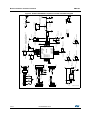
This section describes the X-NUCLEO-IDB04A1 features and provides information which
could be useful for understanding the board schematics.
2.1
X-NUCLEO-IDB04A1 board
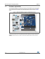
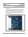
The board allows the user to test the functionality of the BlueNRG processor. It hosts the
innovative BALF-NRG-01D3 balun & harmonic filter and its functionality can be exploited
using the firmware package contained in the X-CUBE-BLE1. It is fundamental to program
the microcontroller on the STM32 Nucleo board. Please refer to user manuals UM1724 and
UM1725, available on www.st.com.
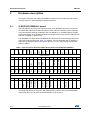
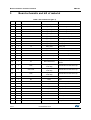
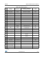
The BlueNRG processor and the STM32 Nucleo board are connected through connectors
CN5, CN6, CN8 and CN9 (see Table 1 for details). The pins indicated with an asterisk (*)
represent an alternative pin for that specific function, i.e. SPI_IRQ could be moved from
CN8.1 to CN5.2.
A0
A1
A2
A3
A4
A5
1
2
3
4
5
6
SPI_IRQ
SPI_CSN*
D6
D5
VIN
GND
GND
5V
3V3
NC
IOREF
RESET
Table 1. Interconnection between STM32 Nucleo board and X-NUCLEO-IDB04A1
D0
D1
D2
D3
D7
D4
8
D8
D12
D14
D15
7
GND
6
D9
D13
5
GND
GND
4
D10
3
D11
2
3V3
1
AREF
Left connectors
Right connectors
3
2
1
8
7
BNRG_RST
4
SPI_MCSN
5
SPI_IRQ*
6
SPI_MOSI
7
SPI_MISO
8
SPI_CLK*
9
GND
10
CN9 digital
6
5
4
3
2
1
SPI_CLK
CN5 digital
To change the default pin SPI_CLK, SPI_IRQ and SPI_CSN the user must disassemble,
respectively,R10, R12 and R15, and assemble R11, R16 and R13.
6/14
DocID026346 Rev 6