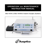
1
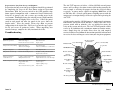
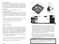
Specifications
Standard Features:
120/230V 50/60Hz, 3/4hp compressor
Aluminum Air Storage Tank
Dual Pass Aftercooler
Auxiliary Equipment Power Supply
Dimensions:
19 x 19 x 17.3 in.
Volume:
3.6 cu. ft.
Weight:
102 lbs.
Noise Level:
< 75dBA
Electrical Requirement:
120/230 Volt, 50/60Hertz
OPERATION AND
MAINTENANCE MANUAL
AA-75CF
(NSN: 6520-01-456-7170) Part 1 of 2
Compressor Motor Performance:
2.9 SCFM @ 100 psi, 60 Hz
2.4 SCFM @ 100 psi, 50 Hz
Air Storage Capacity:
1 U.S. Gallon (3.785 liter)
Auxiliary Equipment Power Outlet:
120 Volt duplex outlet
Operating Temperature:
2° C to 49° C (35° F to 120° F)
For Further Service And/Or Technical Assistance Contact:
P.O. Box 1548 Woodinville, WA 98083
1-800-426-5913 * 425-487-3157 * Fax: 425-487-2608
email: [email protected] * Internet: www.aseptico.com
Printed In The USA
12/98
P/N 420215
P.O. Box 1548 Woodinville, WA 98072-1548
1-800-426-5913 * 425-487-3157 * Fax: 425-487-2608
email: [email protected] * Internet: www.aseptico.com
Table Of Contents
Illustrations
Introduction . . . . . . . . . . . . . . . . . . .2
Component Identification .3
Safety Precautions . . . . . . . . . . . . . .4
Case Top . . . . . . . . . . . . . . .5
Operation Instructions
Pressure Switch . . . . . . . . . .5
Set-Up . . . . . . . . . . . . . . . . . . . . . . . .4
Air Line Connection . . . . .5
Compressor . . . . . . . . . . . . . . . . . . .6
Daily Functional Check List . . . . . .6
Motor won’t start with gauge pressure at 0 psi
The thermal protection of the compressor may have been activated.
If system fans are still functioning, allow the unit to cool briefly and
restart. If system fans are not running, a high amperage condition
existed resulting in the system circuit breaker being tripped. This
condition will result from a leaking check valve or malfunctioning
unloader valve.
Motor experiences labored start with gauge pressure below 70 psi
Case Drain . . . . . . . . . . . . . . . . . . . .7
This condition results from the motor attempting to restart with
pressure in the cylinder. This is an indication of a leaking check valve
or malfunctioning unloader valve. Inspect the check valve and the
unloader switch. Service components as required.
Duplex Outlet . . . . . . . . . . . . . . . . .8
Motor starts at an intermediate pressure or Pressure relief valve is activated
Pressure Switch . . . . . . . . . . . . . . . .6
Air Storage Tank . . . . . . . . . . . . . . .7
Air Flow System . . . . . . . . . . . . . . . .8
Extreme Temperature Operation .9
Long Term Storage Prep. . . . . . . .10
Troubleshooting . . . . . . . . . . . . . . .10
Specifications . . . . . . . . . . . . . . . . .11
INTRODUCTION
Performance in tandem with portability makes the Aseptico
AA-75CF Command Air Portable Air Compressor perfect for the
demanding professional. When used with the ADU-10CF Portable
Dental Field unit, the AA-75CF provides excellent performance for
the needs of today’s field dentistry. At 3.6 cu. ft. (19”x19”x17.3” .) and
102 lbs., the AA-75CF can be easily transported and stored.
Integrated case construction minimizes set-up and tear down times as
well as reduces compressor running noise below 75 dBA. A 3/4 horsepower, twin cylinder, oilless compressor with claimed operating
pressures above 105 psi and flow rates on the order of 2.5 SCFM at
100 psi. is the heart of this unit, while an internal frame provides
protection for the compressor motor and supports the unit’s subsystems.
Disconnect the unit from the power source. Inspect the pressure
switch for excessive wear and damaged or dirty components. Replace
parts as required.
Compressor cycles more frequently than is common
Shut off compressor. Watch the tank pressure gauge. If the tank
pressure drops rapidly, check tubing and fittings for leaks. If tubing
and fittings are satisfactorily connected, the check valve should be
inspected for dirt and damage. If after shut off tank pressure is
maintained, the tank should be blown off. Water vapor can condense
in the tank and reduce its capacity.
Compressor takes longer to build tank pressure than is common
Check system tubing and fittings for leaks. Inspect compressor air
intake filters. Replace filter cartridge if required.
No power to duplex outlet
Verify system is powered. Reset duplex outlet circuit breaker.
A customized air conditioning system composed of a one gallon air
storage tank, an aftercooler, a pair of fans and a pressure switch
minimizes the workload on the compressor and facilitates the delivery
of cool, dry air.
Page 2
Page 11
Preparation for Long Term Storage and Shipment
Preparation for long term storage or shipment should be performed
by completing the steps of the Shut Down section of Operation
Instructions. With the pressure switch in the OFF position, wipe
down exposed components with a commercial dental disinfectant,
drain the air storage tank, and evacuate any standing water in the
case bottom. Thoroughly drying the unit will prevent a high humidity
environment from developing in the sealed case. Collect the power
cords in cord pouch and store the pouch in the space above the
duplex outlet. Place the pouch’s Velcro edge down to prevent
compression of the intake hose. Fold case legs into the top, replace
the lid and secure all perimeter latches. When unpacking after
extended storage, complete the daily functional check list.
Troubleshooting
Symptom
System non-operational
Problem
Action
Main breaker tripped
Reset main breaker
Pressure switch contacts corroded
Replace switch
The AA-75CF operates off either a 120 or 230 Volt external power
source and has voltage detection circuitry which makes powering the
unit as simple as selecting the proper cord for the electrical source
receptacle. A power source capable of supplying 2000 Watts at 120
or 230 Volts and a 3/8 male quick connect coupling to mate with the
compressor’s air output fitting is all that is required to begin using the
AA-75CF.
A duplex outlet provides 120 Volt power to supplemental equipment.
Power outlet and system circuit breakers, a safety relief valve, and a
pressure switch with an unloader valve are included to ensure the
safety of the system and the user. The AA-75CF will provide reliable
service in all conditions with a minimum amount of routine maintenance. Simply keep the air intake filters clean, the tank emptied,
surfaces disinfected and follow the instructions provided in this manual
to receive the best and longest service from your Aseptico equipment.
Case Drain Fitting
Air Storage Tank
Drain Valve
Aftercooler Assembly
Exhaust Baffle
Compressor motor not running
Main breaker tripped
Reset main breaker
Thermal overload tripped
Allow several minutes to cool and restart
No duplex outlet power
Circuit breaker tripped
Reset duplex breaker
Tank pressure exceeds 110 psi.
Pressure switch settings altered
Readjust according to Pressure Switch
Replacement section note
Compressor attempts to
Leaking or obstructed check valve
Disassembly and clean or replace.
restart under load
Misaligned unloader valve
Tighten unloader valve screw and realign.
Extended compressor cycle time
Air demand has been altered
Readjust instruments
Clogged intake filters.
Clean or replace.
Air line leaks.
Tighten couplings, retape.
Water collected in air storage tank.
Blow off tank
Leg Socket
AUTO/OFF Switch
Pressure Switch
Female
Quick Connect
Safety Relief
Valve
Pressure Gauge
System
Circuit Breaker
15 amp.
Intake Fan Filter
Duplex Outlet
Duplex Outlet
Circuit Breaker
2 amp.
Power Inlet
Receptacle
Air Storage Tank
Figure 1
AA-75CF Component Identification
Page 10
Page 3
SAFETY PRECAUTIONS
1. This compressor needs no lubrication and should never be oiled.
Applying oil to any part could result in polluted air delivery to the
air handling equipment.
2. Always run the compressor with the case lid open to ensure proper
cooling of the compressor head and motor.
3. All compressors generate heat even under normal operating conditions. To avoid serious burns, never touch the compressor or
internal parts during or immediately after operation.
4. When unit is not in use, wrap power cords and store inside
compressor. Do not abuse cord.
5. ALWAYS use a grounded 3-prong power cord and grounded
power source.
6. To prevent explosive hazard, DO NOT operate compressor near
combustible liquids or vapors. Personal injury and/or property
damage may result.
Extreme Temperature Operation
When the AA-75CF is to be used in an extremely hot environment
for extended periods of time, the compressor may overheat.
Thermal protection in the compressor will shut off the motor when
this condition arises. If this shut off occurs, additional cooling is
necessary. The compressor cooling can be improved, at the
expense of noise reduction, by removing the compressor from the
hard shell case. Operating the AA-75CF’s compressor’s component module outside the case provides superior air flow and heat
dissipation.
To extract the compressor from hard shell case:
1. Remove case top.
2. Carefully place unit top cover down.
3. Remove the case bumper screws, sealing washers and case
bumpers. Refer to Service Manual Reference figure B.
Note: this will require a 7/16 in. socket wrench.
4. Lift off case bottom.
7. Do not submerge unit in water.
5. Turn the compressor back to upright position.
8. Ambient temperature should not exceed 49°C (120°F).
6. Replace by reversing steps. Secure case bumpers using a thread
locking compound.
9. Always disconnect the power before servicing.
OPERATION INSTRUCTIONS
Set-Up
Shut Down
1. If necessary, drain the case using the saliva ejector body.
1. Unpack the AA-75CF unit from all external packaging. With the
large side of the case down, unlock all perimeter latches and
remove the case top.
2. Perform the end of the day fan filter cleaning and air storage tank
draining procedures. (see Air Storage Tank Operations
Procedures - page 7)
2. Select the power cord appropriate for the power source from the
cord pouch. Reference figure 2.
3. Turn the pressure switch to the OFF position. Allow air storage
tank to drain completely, then close tank drain valve.
3. Swing down the case legs, contained in the case top, and fit them
into the leg sockets on the compressor top cover. The case top will
serve as protection from the elements and offer minor noise
reduction. Reference figure 2.
4. Fold the case legs into the case top.
5. Disconnect the power cord and the air hose and return the power
cord to the cord pouch.
6. Replace the case lid and secure all perimeter latches.
Page 4
Page 9
Duplex Outlet Operation
To accommodate supplemental equipment, the AA-75CF has a
duplex outlet located on the top cover. The outlet will supply 120V
power regardless of the supplied system power and is protected by a
2 amp circuit breaker located next to the outlet cover. Duplex outlet
power is available when the pressure switch is in the AUTO position.
Figure 2
Case Top
Figure 3
Pressure Switch
Case Leg
Cord Pouch
OFF/AUTO Switch
Grounding Lug
Mounting point supplied for attaching an earth ground.
Air Flow System Operation
In order to move fresh air through the AA-75CF, two cooling fans
reside on top cover of the compressor top. These fans activate when
the pressure switch is toggled to the AUTO position. They run while
the compressor is operating and two minutes after the compressor
stops.
Incoming air for both fans is filtered by foam media. After each day
of use, this media should be cleaned. To clean media:
Female Quick Connect
Power Cords
TO AA-75CF
COMPRESSOR
10 ft.
10 ft.
ADU-10CF
UNIT INPUT
1. Remove snap on media guard from fan guard assembly.
2. Extract filter media.
3. Rinse with soapy water.
4. Squeeze dry and replace.
Intake air for the compressor is filtered through two compressor
intake filters. One is located on each compressor head. The felt
media of these filters requires periodic inspection and replacement.
Excessive contamination can reduce compressor output and may
affect service life. If a clean dry operating environment is maintained,
initial inspection is recommended after 500 hours. Humid or wet
conditions require more frequent inspection. To replace filters:
1. Remove lower module from case bottom as per instructions in
Extreme Temperature Operation.
2. Locate air intake filters located on the top of the compressor heads.
3. Grasp filter cap and twist counterclockwise to expose felt media.
4. Remove felt media and replace with part #730382.
Page 8
Figure 4 - Air Supply Line Connection
4. With the OFF/AUTO switch of the pressure switch in the OFF
position, plug the female end of the selected power cord into the
power inlet receptacle on the compressor and the other end into
an appropriate power source. At this time the compressor circuitry
will detect the line voltage and select appropriate operating conditions. If 230 Volt power is detected, a click will be audible as
voltage selector relays switch. Voltage should not hereafter be
changed during operation. Reference figure 3.
5. From the ADU-10CF air hose package, locate the 3/8” male-male
air hose. Connect 3/8” male-male quick connect air hose to the
female air output connector on compressor. Connect the femalemale extension air hose, if desired. Connect to the ADU-10CF
dental unit. See figures 3 & 4.
! WARNING ! Do not start the compressor with the male-male hose
installed only to the compressor module. Connection in this
manner may result in injury to user. The other end of the air hose
must be connected to the delivery unit.
Page 5
Compressor Operation
1. With the steps of the Set-Up section complete, toggle the pressure
switch to the AUTO position. The compressor will then fill the air
storage tank and cutoff, indicating full pressure.
2. As air is consumed in normal operation, the compressor will cycle
when the air storage tank pressure falls below 70 psi until it
reaches 105 psi.
If the compressor is to remain idle for an extended period of time,
toggle the pressure switch to the OFF position.
Should this breaker be tripped, turn pressure switch to the OFF
position. Reset system circuit breaker. Restart compressor
according to the Operating Instructions.
3. Attached to the pressure switch are a female quick connect fitting,
a pressure relief valve, and a 0-160 psi pressure gauge.
4. The female quick connect fitting is the attachment point for an air
line to the ADU-10CF Field Unit.
5. The pressure relief valve prevents over pressurizing the tank in the
unlikely event of a pressure switch failure.
Daily Functional Checklist
With the AA-75CF compressor connected to a power supply, operation of the following components ensures full function performance.
Compressor motor functions.
Air storage tank maintains pressure.
Pressure switch dictates a cut off pressure of 105psi + 5psi and
a restart pressure of 70 psi + 10psi
Pressure switch unloader valve actuates relieving intake line
pressure.
Aftercooler and intake fans operate while the compressor
runs and two minutes after compressor cut off.
Duplex outlet provides auxiliary equipment power, 120V.
Pressure Switch Operation
1. The pressure switch serves as the primary power switch for the
AA-75CF compressor. The switch is preset for cut off, 105 psi, and
cut in, 75 psi, air storage tank pressures, and is equipped with an
unloader valve which relieves the compressor cylinder pressure
when the maximum tank pressure is reached. If for any reason the
compressor stops before the maximum tank pressure is achieved,
the cylinder pressure can be relieved manually by toggling the
pressure switch to the OFF position. This process will prevent a
high current compressor start.
2. The system is protected from high current damage by a 15 Amp
system circuit breaker located behind the power inlet receptacle.
Page 6
6. The pressure gauge offers a visual indication that the air storage
tank is maintaining pressure properly.
Air Storage Tank Operation
Located between the aftercooler assembly and the exhaust baffle
chassis is a valve used for draining the air storage tank. During
normal use moisture from system air will condense in the tank. To
prevent excessive moisture accumulation, the air storage tank should
be drained daily.
1. Check that some air pressure is present in the tank.
2. Point the case side tank drain tube away from compressor and
open the drain valve fitting.
3. Vent the air storage tank until most of the water is drained then
close the drain valve fitting.
This procedure will both blow off water and bleed the tank of
pressure for storage or transportation. When operating in wet or
humid environments, water build up may increase. Shortened cycle
time may indicate reduced air storage tank capacity. Drain air storage
tank as necessary.
Case Drain Operation
When operating in wet weather conditions, water may collect in the
case bottom from rain contact and moisture in the intake air. This
water can be removed by attaching the saliva ejector body from the
ADU-10CF to the case drain fitting and applying vacuum.
Page 7
Duplex Outlet Operation
To accommodate supplemental equipment, the AA-75CF has a
duplex outlet located on the top cover. The outlet will supply 120V
power regardless of the supplied system power and is protected by a
2 amp circuit breaker located next to the outlet cover. Duplex outlet
power is available when the pressure switch is in the AUTO position.
Figure 2
Case Top
Figure 3
Pressure Switch
Case Leg
Cord Pouch
OFF/AUTO Switch
Grounding Lug
Mounting point supplied for attaching an earth ground.
Air Flow System Operation
In order to move fresh air through the AA-75CF, two cooling fans
reside on top cover of the compressor top. These fans activate when
the pressure switch is toggled to the AUTO position. They run while
the compressor is operating and two minutes after the compressor
stops.
Incoming air for both fans is filtered by foam media. After each day
of use, this media should be cleaned. To clean media:
Female Quick Connect
Power Cords
TO AA-75CF
COMPRESSOR
10 ft.
10 ft.
ADU-10CF
UNIT INPUT
1. Remove snap on media guard from fan guard assembly.
2. Extract filter media.
3. Rinse with soapy water.
4. Squeeze dry and replace.
Intake air for the compressor is filtered through two compressor
intake filters. One is located on each compressor head. The felt
media of these filters requires periodic inspection and replacement.
Excessive contamination can reduce compressor output and may
affect service life. If a clean dry operating environment is maintained,
initial inspection is recommended after 500 hours. Humid or wet
conditions require more frequent inspection. To replace filters:
1. Remove lower module from case bottom as per instructions in
Extreme Temperature Operation.
2. Locate air intake filters located on the top of the compressor heads.
3. Grasp filter cap and twist counterclockwise to expose felt media.
4. Remove felt media and replace with part #730382.
Page 8
Figure 4 - Air Supply Line Connection
4. With the OFF/AUTO switch of the pressure switch in the OFF
position, plug the female end of the selected power cord into the
power inlet receptacle on the compressor and the other end into
an appropriate power source. At this time the compressor circuitry
will detect the line voltage and select appropriate operating conditions. If 230 Volt power is detected, a click will be audible as
voltage selector relays switch. Voltage should not hereafter be
changed during operation. Reference figure 3.
5. From the ADU-10CF air hose package, locate the 3/8” male-male
air hose. Connect 3/8” male-male quick connect air hose to the
female air output connector on compressor. Connect the femalemale extension air hose, if desired. Connect to the ADU-10CF
dental unit. See figures 3 & 4.
! WARNING ! Do not start the compressor with the male-male hose
installed only to the compressor module. Connection in this
manner may result in injury to user. The other end of the air hose
must be connected to the delivery unit.
Page 5
SAFETY PRECAUTIONS
1. This compressor needs no lubrication and should never be oiled.
Applying oil to any part could result in polluted air delivery to the
air handling equipment.
2. Always run the compressor with the case lid open to ensure proper
cooling of the compressor head and motor.
3. All compressors generate heat even under normal operating conditions. To avoid serious burns, never touch the compressor or
internal parts during or immediately after operation.
4. When unit is not in use, wrap power cords and store inside
compressor. Do not abuse cord.
5. ALWAYS use a grounded 3-prong power cord and grounded
power source.
6. To prevent explosive hazard, DO NOT operate compressor near
combustible liquids or vapors. Personal injury and/or property
damage may result.
Extreme Temperature Operation
When the AA-75CF is to be used in an extremely hot environment
for extended periods of time, the compressor may overheat.
Thermal protection in the compressor will shut off the motor when
this condition arises. If this shut off occurs, additional cooling is
necessary. The compressor cooling can be improved, at the
expense of noise reduction, by removing the compressor from the
hard shell case. Operating the AA-75CF’s compressor’s component module outside the case provides superior air flow and heat
dissipation.
To extract the compressor from hard shell case:
1. Remove case top.
2. Carefully place unit top cover down.
3. Remove the case bumper screws, sealing washers and case
bumpers. Refer to Service Manual Reference figure B.
Note: this will require a 7/16 in. socket wrench.
4. Lift off case bottom.
7. Do not submerge unit in water.
5. Turn the compressor back to upright position.
8. Ambient temperature should not exceed 49°C (120°F).
6. Replace by reversing steps. Secure case bumpers using a thread
locking compound.
9. Always disconnect the power before servicing.
OPERATION INSTRUCTIONS
Set-Up
Shut Down
1. If necessary, drain the case using the saliva ejector body.
1. Unpack the AA-75CF unit from all external packaging. With the
large side of the case down, unlock all perimeter latches and
remove the case top.
2. Perform the end of the day fan filter cleaning and air storage tank
draining procedures. (see Air Storage Tank Operations
Procedures - page 7)
2. Select the power cord appropriate for the power source from the
cord pouch. Reference figure 2.
3. Turn the pressure switch to the OFF position. Allow air storage
tank to drain completely, then close tank drain valve.
3. Swing down the case legs, contained in the case top, and fit them
into the leg sockets on the compressor top cover. The case top will
serve as protection from the elements and offer minor noise
reduction. Reference figure 2.
4. Fold the case legs into the case top.
5. Disconnect the power cord and the air hose and return the power
cord to the cord pouch.
6. Replace the case lid and secure all perimeter latches.
Page 4
Page 9
Preparation for Long Term Storage and Shipment
Preparation for long term storage or shipment should be performed
by completing the steps of the Shut Down section of Operation
Instructions. With the pressure switch in the OFF position, wipe
down exposed components with a commercial dental disinfectant,
drain the air storage tank, and evacuate any standing water in the
case bottom. Thoroughly drying the unit will prevent a high humidity
environment from developing in the sealed case. Collect the power
cords in cord pouch and store the pouch in the space above the
duplex outlet. Place the pouch’s Velcro edge down to prevent
compression of the intake hose. Fold case legs into the top, replace
the lid and secure all perimeter latches. When unpacking after
extended storage, complete the daily functional check list.
Troubleshooting
Symptom
System non-operational
Problem
Action
Main breaker tripped
Reset main breaker
Pressure switch contacts corroded
Replace switch
The AA-75CF operates off either a 120 or 230 Volt external power
source and has voltage detection circuitry which makes powering the
unit as simple as selecting the proper cord for the electrical source
receptacle. A power source capable of supplying 2000 Watts at 120
or 230 Volts and a 3/8 male quick connect coupling to mate with the
compressor’s air output fitting is all that is required to begin using the
AA-75CF.
A duplex outlet provides 120 Volt power to supplemental equipment.
Power outlet and system circuit breakers, a safety relief valve, and a
pressure switch with an unloader valve are included to ensure the
safety of the system and the user. The AA-75CF will provide reliable
service in all conditions with a minimum amount of routine maintenance. Simply keep the air intake filters clean, the tank emptied,
surfaces disinfected and follow the instructions provided in this manual
to receive the best and longest service from your Aseptico equipment.
Case Drain Fitting
Air Storage Tank
Drain Valve
Aftercooler Assembly
Exhaust Baffle
Compressor motor not running
Main breaker tripped
Reset main breaker
Thermal overload tripped
Allow several minutes to cool and restart
No duplex outlet power
Circuit breaker tripped
Reset duplex breaker
Tank pressure exceeds 110 psi.
Pressure switch settings altered
Readjust according to Pressure Switch
Replacement section note
Compressor attempts to
Leaking or obstructed check valve
Disassembly and clean or replace.
restart under load
Misaligned unloader valve
Tighten unloader valve screw and realign.
Extended compressor cycle time
Air demand has been altered
Readjust instruments
Clogged intake filters.
Clean or replace.
Air line leaks.
Tighten couplings, retape.
Water collected in air storage tank.
Blow off tank
Leg Socket
AUTO/OFF Switch
Pressure Switch
Female
Quick Connect
Safety Relief
Valve
Pressure Gauge
System
Circuit Breaker
15 amp.
Intake Fan Filter
Duplex Outlet
Duplex Outlet
Circuit Breaker
2 amp.
Power Inlet
Receptacle
Air Storage Tank
Figure 1
AA-75CF Component Identification
Page 10
Page 3
Table Of Contents
Illustrations
Introduction . . . . . . . . . . . . . . . . . . .2
Component Identification .3
Safety Precautions . . . . . . . . . . . . . .4
Case Top . . . . . . . . . . . . . . .5
Operation Instructions
Pressure Switch . . . . . . . . . .5
Set-Up . . . . . . . . . . . . . . . . . . . . . . . .4
Air Line Connection . . . . .5
Compressor . . . . . . . . . . . . . . . . . . .6
Daily Functional Check List . . . . . .6
Motor won’t start with gauge pressure at 0 psi
The thermal protection of the compressor may have been activated.
If system fans are still functioning, allow the unit to cool briefly and
restart. If system fans are not running, a high amperage condition
existed resulting in the system circuit breaker being tripped. This
condition will result from a leaking check valve or malfunctioning
unloader valve.
Motor experiences labored start with gauge pressure below 70 psi
Case Drain . . . . . . . . . . . . . . . . . . . .7
This condition results from the motor attempting to restart with
pressure in the cylinder. This is an indication of a leaking check valve
or malfunctioning unloader valve. Inspect the check valve and the
unloader switch. Service components as required.
Duplex Outlet . . . . . . . . . . . . . . . . .8
Motor starts at an intermediate pressure or Pressure relief valve is activated
Pressure Switch . . . . . . . . . . . . . . . .6
Air Storage Tank . . . . . . . . . . . . . . .7
Air Flow System . . . . . . . . . . . . . . . .8
Extreme Temperature Operation .9
Long Term Storage Prep. . . . . . . .10
Troubleshooting . . . . . . . . . . . . . . .10
Specifications . . . . . . . . . . . . . . . . .11
INTRODUCTION
Performance in tandem with portability makes the Aseptico
AA-75CF Command Air Portable Air Compressor perfect for the
demanding professional. When used with the ADU-10CF Portable
Dental Field unit, the AA-75CF provides excellent performance for
the needs of today’s field dentistry. At 3.6 cu. ft. (19”x19”x17.3” .) and
102 lbs., the AA-75CF can be easily transported and stored.
Integrated case construction minimizes set-up and tear down times as
well as reduces compressor running noise below 75 dBA. A 3/4 horsepower, twin cylinder, oilless compressor with claimed operating
pressures above 105 psi and flow rates on the order of 2.5 SCFM at
100 psi. is the heart of this unit, while an internal frame provides
protection for the compressor motor and supports the unit’s subsystems.
Disconnect the unit from the power source. Inspect the pressure
switch for excessive wear and damaged or dirty components. Replace
parts as required.
Compressor cycles more frequently than is common
Shut off compressor. Watch the tank pressure gauge. If the tank
pressure drops rapidly, check tubing and fittings for leaks. If tubing
and fittings are satisfactorily connected, the check valve should be
inspected for dirt and damage. If after shut off tank pressure is
maintained, the tank should be blown off. Water vapor can condense
in the tank and reduce its capacity.
Compressor takes longer to build tank pressure than is common
Check system tubing and fittings for leaks. Inspect compressor air
intake filters. Replace filter cartridge if required.
No power to duplex outlet
Verify system is powered. Reset duplex outlet circuit breaker.
A customized air conditioning system composed of a one gallon air
storage tank, an aftercooler, a pair of fans and a pressure switch
minimizes the workload on the compressor and facilitates the delivery
of cool, dry air.
Page 2
Page 11
Specifications
Standard Features:
120/230V 50/60Hz, 3/4hp compressor
Aluminum Air Storage Tank
Dual Pass Aftercooler
Auxiliary Equipment Power Supply
Dimensions:
19 x 19 x 17.3 in.
Volume:
3.6 cu. ft.
Weight:
102 lbs.
Noise Level:
< 75dBA
Electrical Requirement:
120/230 Volt, 50/60Hertz
OPERATION AND
MAINTENANCE MANUAL
AA-75CF
(NSN: 6520-01-456-7170) Part 1 of 2
Compressor Motor Performance:
2.9 SCFM @ 100 psi, 60 Hz
2.4 SCFM @ 100 psi, 50 Hz
Air Storage Capacity:
1 U.S. Gallon (3.785 liter)
Auxiliary Equipment Power Outlet:
120 Volt duplex outlet
Operating Temperature:
2° C to 49° C (35° F to 120° F)
For Further Service And/Or Technical Assistance Contact:
P.O. Box 1548 Woodinville, WA 98083
1-800-426-5913 * 425-487-3157 * Fax: 425-487-2608
email: [email protected] * Internet: www.aseptico.com
Printed In The USA
12/98
P/N 420215
P.O. Box 1548 Woodinville, WA 98072-1548
1-800-426-5913 * 425-487-3157 * Fax: 425-487-2608
email: [email protected] * Internet: www.aseptico.com