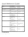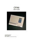
1
TS790 / TS900 Intruder Alarm Control Panels _ ~ SYSTEM OPEN 17:30 Wed 11 NOV A 1 2 B 4 5 C 7 8 9 D ENT 0 ESC 3 6 Sett ing the Syst em Ent er your pa ss code XXXX th en lea v e th e pro tec t ed a re a. Unsetting the System Go dir e ct ly to t he ke yp ad and en ter you r p as scod e XXXX . Ent er your pa ss code XXXX f ollow ed by EN T the n 3. Te leph on e you r a lar m com pan y and follow th eir instr uct io ns. ! OPEN _ ~ See U ser Manual A Part Set B Part Set Resetting 1 2 BELL TEST WALK TEST 4 NEW CODE 3 RESET 5 6 CHIME 24 Hr OMIT C 7 8 Part Set ZONE OMIT SILENT D ENT 0 9 ESC FULL SET _ OPEN ~ Engineers menu 2 Select option :- User Manual Engineers menu 2 Select option :- _ ~ Quick Reference Guide Full Set Enter your passcode ???? Part Set Enter your passcode ???? Press A, B or C as required A or B or C Unset Enter your passcode ???? Silent Full Set Enter your passcode ???? Press 8 8 Silent Part Set Bell Test Walk Test Remote Reset Enter your passcode ???? Press A, B or C as required A or B or C Press 8 8 Enter your passcode ???? Press [ENT] within 5 secs. [ Press 1 (sounders on) 1 Press [ESC] when finished ] Enter your passcode ???? Press [ENT] within 5 secs. [ Press 2 2 Conduct Walk Test Conduct Walk Test Press [ESC] when finished ] Enter your passcode ???? Press [ENT] within 5 secs. [ Press 3 3 Contact your central station and quote 4 digit number Enter reply number Change Passcode Overview ???? Press [ENT] [ Press [ESC] when finished ] Enter your passcode ???? Press [ENT] within 5 secs. [ Press 4 4 Enter new passcode ???? Press [ENT] to accept [ Press [ESC] when finished ] CONTENTS Quick Reference Guide Overview Introduction. . . . . . . . . . . . . . . . . . . . . . . . . . . . . . . . . . . . . . . . . . . . 1 Remote Keypads . . . . . . . . . . . . . . . . . . . . . . . . . . . . . . . . . . . . . . . 2 Arming Station. . . . . . . . . . . . . . . . . . . . . . . . . . . . . . . . . . . . . . . . . . 2 LED Keypad . . . . . . . . . . . . . . . . . . . . . . . . . . . . . . . . . . . . . . . . . . . 2 Starburst Keypad . . . . . . . . . . . . . . . . . . . . . . . . . . . . . . . . . . . . . . . . 3 LCD Keypad . . . . . . . . . . . . . . . . . . . . . . . . . . . . . . . . . . . . . . . . . . . 3 Operating The System Introduction. . . . . . . . . . . . . . . . . . . . . . . . . . . . . . . . . . . . . . . . . . . . 4 User Menus . . . . . . . . . . . . . . . . . . . . . . . . . . . . . . . . . . . . . . . . . . . . 4 Engineer on Site Message. . . . . . . . . . . . . . . . . . . . . . . . . . . . . . . . . 4 Full Setting The System . . . . . . . . . . . . . . . . . . . . . . . . . . . . . . . . . . . 5 Unsetting The System. . . . . . . . . . . . . . . . . . . . . . . . . . . . . . . . . . . . . 6 Part-Setting Using The Part-Set Buttons . . . . . . . . . . . . . . . . . . . . . . . . 7 Part-Setting With Part Set Passcodes . . . . . . . . . . . . . . . . . . . . . . . . . 8 Silent Setting . . . . . . . . . . . . . . . . . . . . . . . . . . . . . . . . . . . . . . . . . . 10 Unsetting After An Alarm . . . . . . . . . . . . . . . . . . . . . . . . . . . . . . . . . 11 Resetting After An Alarm . . . . . . . . . . . . . . . . . . . . . . . . . . . . . . . . . 11 User Reset . . . . . . . . . . . . . . . . . . . . . . . . . . . . . . . . . . . . . . . . . . . 11 Engineer Reset . . . . . . . . . . . . . . . . . . . . . . . . . . . . . . . . . . . . . . 12 Remote Reset . . . . . . . . . . . . . . . . . . . . . . . . . . . . . . . . . . . . . . . 12 Setting individual Wards with Standard User Passcodes. . . . . . . . . . 13 Unsetting individual Wards with Standard User Passcodes . . . . . . . . 14 Setting & Unsetting Wards with the Code Set Group Passcodes . . . 16 User Menu 1 Introduction. . . . . . . . . . . . . . . . . . . . . . . . . . . . . . . . . . . . . . . . . . . 17 Bell Test - [1.1] . . . . . . . . . . . . . . . . . . . . . . . . . . . . . . . . . . . . . . . . . 18 Walk Test - [1.2] . . . . . . . . . . . . . . . . . . . . . . . . . . . . . . . . . . . . . . . . 18 Remote Reset - [1.3] . . . . . . . . . . . . . . . . . . . . . . . . . . . . . . . . . . . . 19 Change Passcode - [1.4] . . . . . . . . . . . . . . . . . . . . . . . . . . . . . . . . 19 Enable Chime - [1.5]. . . . . . . . . . . . . . . . . . . . . . . . . . . . . . . . . . . . 19 Omit 24 Hour Group - [1.6] . . . . . . . . . . . . . . . . . . . . . . . . . . . . . . . 20 Omitting Circuits - [1.7] . . . . . . . . . . . . . . . . . . . . . . . . . . . . . . . . . . 20 Silent Set - [1.8] . . . . . . . . . . . . . . . . . . . . . . . . . . . . . . . . . . . . . . . . 22 View Activity Count - [1.9] . . . . . . . . . . . . . . . . . . . . . . . . . . . . . . . . 22 Full Set and Part-set - [1.0,A,B,C] . . . . . . . . . . . . . . . . . . . . . . . . . . . 22 User Menu 2 Introduction. . . . . . . . . . . . . . . . . . . . . . . . . . . . . . . . . . . . . . . . . . . 23 View Circuits - [2.1] . . . . . . . . . . . . . . . . . . . . . . . . . . . . . . . . . . . . . 24 Set Clock - [2.2]. . . . . . . . . . . . . . . . . . . . . . . . . . . . . . . . . . . . . . . . 24 Set Date - [2.3] . . . . . . . . . . . . . . . . . . . . . . . . . . . . . . . . . . . . . . . . 25 Setup Users - [2.4] . . . . . . . . . . . . . . . . . . . . . . . . . . . . . . . . . . . . . . 25 Alter Chime Circuits - [2.5]. . . . . . . . . . . . . . . . . . . . . . . . . . . . . . . . 28 Alter 24Hr Group - [2.6] . . . . . . . . . . . . . . . . . . . . . . . . . . . . . . . . . . 28 Print System Log - [2.7] . . . . . . . . . . . . . . . . . . . . . . . . . . . . . . . . . . 29 Configure Wards - [2.8] . . . . . . . . . . . . . . . . . . . . . . . . . . . . . . . . . . 30 Viewing the System Log with an LCD Remote Keypad - [2.9] . . . . . 31 Viewing The Log With an LED or Starburst Remote Keypad - [2.9] . . 31 Remote Call Back - [2.0] . . . . . . . . . . . . . . . . . . . . . . . . . . . . . . . . . 33 Initiate Remote Service Call - [2.A] . . . . . . . . . . . . . . . . . . . . . . . . . 34 User Menu 3 Introduction. . . . . . . . . . . . . . . . . . . . . . . . . . . . . . . . . . . . . . . . . . . 35 Time Switch A, B & C - [3.1] . . . . . . . . . . . . . . . . . . . . . . . . . . . . . . . 36 Selecting Time Switches. . . . . . . . . . . . . . . . . . . . . . . . . . 36 Setting The On Times . . . . . . . . . . . . . . . . . . . . . . . . . . . . 36 Setting The Off Times . . . . . . . . . . . . . . . . . . . . . . . . . . . . 37 Setting The Days Of Operation . . . . . . . . . . . . . . . . . . . . 37 Setting The Day . . . . . . . . . . . . . . . . . . . . . . . . . . . . . . . . 38 Manually Switching The Output . . . . . . . . . . . . . . . . . . . . 38 Part Set Groups - [3.2] . . . . . . . . . . . . . . . . . . . . . . . . . . . . . . . . . . . 39 Code Set Groups - [3.3] . . . . . . . . . . . . . . . . . . . . . . . . . . . . . . . . . 40 User Names (TS900 Remote Keypads Only) - [3.4] . . . . . . . . . . . . . 41 Edit Text For Part Set Groups (TS900 Remote Keypads Only) - [3.5] . 41 Edit Circuit Text (TS900 Remote Keypad Only) - [3.6] . . . . . . . . . . . . 42 View Inactive Circuits - [3.0] . . . . . . . . . . . . . . . . . . . . . . . . . . . . . . 43 Text Keypad . . . . . . . . . . . . . . . . . . . . . . . . . . . . . . . . . . . . . . . . . . 44 Fault Finding Display Messages . . . . . . . . . . . . . . . . . . . . . . . . . . . . . . . . . . . . . . 45 Display Messages (Cont.) . . . . . . . . . . . . . . . . . . . . . . . . . . . . . . . . 46 Glossary of Terms . . . . . . . . . . . . . . . . . . . . . . . . . . . . . . . . . . . . . . 47 TS790/TS900 User Manual Overview Introduction The TS790 and TS900 are advanced security alarm control systems using state of the art electronics to provide comprehensive but flexible protection for both domestic and commercial premises. The system comprises of a number of components linked to a central control unit which is concealed from view but accessible for maintenance. The TS790 can monitor from 10 to 16 detection circuits whereas the TS900 can monitor a maximum of 56. Both systems can be operated from up to four remote keypads which may be one of four types. Detection devices such as door contacts or movement sensors are allocated to detection circuits which are identified on the remote keypad displays. All detection circuits may then be allocated to the whole system or grouped into “Wards” (areas) so that access to certain areas can be controlled independently. A modem can also be connected to the alarm system via the telephone line to allow remote interrogation, programming and resetting of alarms. This feature is known as “Downloading” and is normally performed by the installation company or central station. Each alarm installation is specific to the site and its occupier and may differ from other TS790/TS900 installations. This manual describes in detail all the functions and procedures available to the user, however, not all these may be relevant to the way your system is set up. To avoid unnecessary operating errors please discuss the details of the alarm system with your installation company before attempting to use it. Also ensure that installation company complete the system record sheets at the back of this manual and fill in the details required within the section called “Operating The System”. 1 Overview TS790/TS900 User Manual Remote Keypads Your alarm system can be operated from one or more remote keypads, which will have been strategically located within the protected premises. The remote keypads may be one of four types. Arming Station The remote arming station can only be used to full set, part set and unset your alarm system. Green Power Indicator - Flashes if no mains power is present. Steady when mains power is present. Red Function Indicator - Can be programmed by the alarm company, to indicate a fault, set or part-set etc. Keyboard - Used for operating your alarm system. Cover - Fold-down cover with quick guide operating instructions. _ ~ A 1 2 3 B 4 5 6 C 7 8 9 D ENT 0 ESC Setting the System Ent er your pa sscode XXXX th en lea ve th e pro tect ed a re a. Unsetting the System Go dire ct ly to t he ke yp ad and en ter you r p asscod e XXXX . 1 2 B ELL TES T WALK TEST B Part Set Resetting Ent er your pa sscode XXXX f ollow ed by EN T the n 3. Te leph on e you r a larm com pan y and follow th eir instruct io ns. ! A Part Set 4 NE W CODE 3 RE SET 5 6 CHIME 24 Hr OMIT C 7 8 Part Set ZONE OM IT SILENT D ENT 0 9 ESC FULL S ET See User Manual LED Keypad The LED remote keypad can be used to full set, part set and unset the alarm system. It also can be used for limited programming functions. 2 LED Display - Used to show the system time along with other system messages. Green Power Indicator - Flashes if no mains power is present. Steady when mains power is present. Red Function Indicator - Can be programmed by the alarm company, to indicate a fault, set or part-set etc. Keyboard - Used for operating your alarm system. Cover - Fold-down cover with quick guide operating instructions. _ OPEN ~ A 1 2 3 B 4 5 6 C 7 8 9 D ENT 0 ESC Setting the System Ent er your pa sscode XXXX th en lea ve th e pro tect ed a re a. Unsetting the System Go dire ct ly to t he ke yp ad and en ter you r p asscod e XXXX . Resetting Ent er your pa sscode XXXX f ollow ed by EN T the n 3. Te leph on e you r a larm com pan y and follow th eir instruct io ns. ! See User Manual A 1 2 Part Set B ELL TES T WALK TEST B Part Set 4 NE W CODE 3 RE SET 5 6 CHIME 24 Hr OMIT C 7 8 Part Set ZONE OM IT SILENT D ENT 0 FULL S ET 9 ESC TS790/TS900 User Manual Overview Starburst Keypad The Starburst remote keypad can be used to full set, part set and unset the alarm system. It also can be used for limited programming functions. Starburst Display - Used to show the system time along with other system messages. Green Power Indicator - Flashes if no mains power is present. Steady when mains power is present. Red Function Indicator - Can be programmed by the alarm company, to indicate a fault, set or part-set etc. Keyboard - Used for operating your alarm system. Cover - Fold-down cover with quick guide operating instructions. _ ~ OPEN A 1 2 3 B 4 5 6 C 7 8 9 D ENT 0 ESC Setting the System Ent er your pa sscode XXXX th en lea ve th e pro tect ed a re a. Unsetting the System Go dire ct ly to t he ke yp ad and en ter you r p asscod e XXXX . Ent er your pa sscode XXXX f ollow ed by EN T the n 3. Te leph on e you r a larm com pan y and follow th eir instruct io ns. ! A 1 2 Part Set B ELL TES T WALK TEST B Part Set Resetting 4 NE W CODE 3 RE SET 5 6 CHIME 24 Hr OMIT C 7 8 Part Set ZONE OM IT SILENT D ENT 0 9 ESC FULL S ET See User Manual LCD Keypad The LCD remote keypad is a full function keypad and can be used to program, test, set and unset the alarm system. LCD Display - Used to show the system time along with other system messages. Green Power Indicator - Flashes if no mains power is present. Steady when mains power is present. Red Function Indicator - Can be programmed by the alarm company, to indicate a fault, set or part-set etc. Keyboard - Used for operating your alarm system. Cover - Fold-down cover with quick guide operating instructions. SYSTEM OPEN 17:30 Mon 01 JAN _ ~ A 1 2 3 B 4 5 6 C 7 8 9 D ENT 0 ESC Setting the System Ent er your pa sscode XXXX th en lea ve th e pro tect ed a re a. Unsetting the System Go dire ct ly to t he ke yp ad and en ter you r p asscod e XXXX . Resetting Ent er your pa sscode XXXX f ollow ed by EN T the n 3. Te leph on e you r a larm com pan y and follow th eir instr uct io ns. ! See U ser Manual A 1 2 Part Set BELL TEST WALK TEST B Part Set 4 NEW CODE 3 RESET 5 6 CHIME 24 Hr OMIT 9 C 7 8 Part Set ZONE OMIT SILENT D ENT 0 ESC FULL SET 3 Operating The System TS790/TS900 User Manual Operating The System Introduction Initial access to the system is gained by entering a 4 digit passcode. Every time you wish to use the system your passcode must be entered correctly. If a passcode is repeatedly entered incorrectly a code tamper alarm will be generated. Up to 31 separate user passcodes are available for operating the system. The master user (user 01) is the person responsible for allocating other users to the system. Each user (02-31) may be defined for different authorisation levels. See page 25 for full details, the table below shows the code levels and their menu access: Code level Master Standard Holiday Set Only Reset Only PA Code Access Full Set Group Code Set Group A Code Set Group B Code Set Group C User Menu 1 User Menu 2 User Menu 3 4 4 4 4 4* 4* Options 1-9 only 4 Used for access control Only allows setting and unsetting of selected wards * If the installation company has programmed the master user for limited access, he or she will NOT have access to “User menu 2" options 6 and 8, and all options in ”User menu 3". User Menus In general when ever a user passcode is entered the system will enter into a 5 second function mode, if the [ button is pressed during this time “User menu 1" is selected, as a reminder, a brief description of each menu option within ”User menu 1 “ is printed underneath each button on the the remote keypads, e.g., button 1 selects the ”Bell Test" option. If the [ button is not pressed within 5 seconds the system will attempt to full set. When any of the menu options are selected the user may abandon the function by pressing the ] button. If the ] button is repeatedly pressed whilst one of the user menus is selected, the alarm system will return to the normal “OPEN” condition. Engineer on Site Message When the installation engineer attends the site for routine maintenance etc. the remote keypads may show “Engineer on site” (ENG ON SITE), whilst this message is displayed the alarm system remains fully operational. However, before the engineer leaves the site he should ask one of the users to enter their passcode followed by ], this will clear the "Engineer on site” message and return the system to the normal “OPEN” condition. 4 TS790 & TS900 User Manual Operating The System Full Setting The System The full setting procedure may be initiated from any remote keypad (if more than one is fitted). Before attempting to full set the alarm system ensure that all movement detectors are unobstructed and all doors, and windows are secure. The installation company will have set-up your alarm system to full set by one of the following: Timed Exit - After entering your passcode the alarm system will be full set after the pre-programmed exit timer has expired. The display at step (2) will count down the remaining exit time. Final Exit - After entering your passcode the alarm system will be full set after the Final Exit door is opened and closed. The display at step (2) will show a count of 9999. Exit Terminator - After entering your passcode the alarm system will be full set after the Final Exit door is opened and closed, and after pressing the Exit Terminator button (a push button normally mounted outside of the premises). The display at step (2) will show a count of 9999. Instant - After entering your passcode the alarm system will be full set after 5 seconds. + » If an attempt is made to full set the system whilst any circuits are active (such as a door being open) the display at step (2) will indicate the circuit(s) that are in fault and internal sounder generates an interrupted tone. The fault must be cleared before the setting procedure can be completed. If the system is set by "Timed Exit" or "Instant", and the fault is still present at the end of the exit time an internal alarm will be generated. If fitted, the external strobe light will flash indicating that the system has “Failed to set”. To prevent this alarm simply re-enter your passcode before the exit timer expires. To full set the system proceed as follows: 1. Enter your passcode ? ? ? ?. The display will show: 2. After 5 seconds the exit sounder will start and the display will show: LCD Press ENT to Select Functions Please Exit Now. Time left > 9999 Starburst LED FUNCTION Func. 9999 9999 3. Leave via the prescribed exit route. 4. The system is set when the exit time has expired, on activation of the Final Exit circuit or pressing the Exit Terminator button, as appropriate. The exit sounder will stop and the display will show: 5. After 5 seconds the “SYSTEM SET” message will disappear and the display will show the time, (date and banner text, LCD only) e.g., SYSTEM SET 05:30 Sun 28 APR ABC SECURITY 05:30 Sun 28 APR Setting Mode: Timed o Final Exit o Exit Time: ________________________ SET 05:30 Exit Terminator o SET 05.30 Instant o 5 Operating The System TS790 & TS900 User Manual Unsetting The System The unsetting of the alarm system can be performed from any remote keypad. » To unset your alarm system, proceed as follows: 1. Enter the premises via the prescribed entry route and proceed directly to the remote keypad. The internal sounders generate an interrupted tone. The display will show the remaining entry time, e.g., 2. Enter your passcode ? ? ? ? before the entry timer expires. The internal sounders will stop and the display will show: 3. After 5 seconds the “SYSTEM OPEN” message will disappear and the display will show the time, (date and banner text, LCD only) e.g., + + 6 LCD Enter Your Code Time left > 0025 SYSTEM OPEN 08:30 Sun 28 APR ABC SECURITY 08:30 Sun 28 APR Starburst LED 0025 0025 OPEN OPEN 08:30 08.30 If the entry time is exceeded an alarm is generated from the internal sounders and the “Second Entry” timer is started. If at the end of the “Second Entry” timer the alarm system has not been unset a full alarm condition will occur. If the installation company has set the “Second Entry” timer to zero the full alarm will occur when the first entry timer expires. If during the entry procedure the user strays from the prescribed entry route and activates a detection circuit a full alarm will occur (internal sounders and external sounders). If the alarm system is fitted with a remote signalling device such as a digicom this will also be triggered and police action will be taken. However, the alarm system may be programmed with an “Entry Abort” feature which will allow a further preset time delay to occur if a detection circuit is accidentally triggered during the entry procedure. This will delay the triggering of the remote signalling device and allow the user time to unset the system. The delay is normally set to 90 seconds by your installation company. Full Set Entry Time: __________________ Second Entry Time: __________________ Part-set Entry Time: __________________ Entry Abort Delay: __________________ TS790 & TS900 User Manual Operating The System Part-Setting Using The Part-Set Buttons The TS790 & TS900 can have up to three predefined part-set configurations. Each configuration allows the alarm system to set with one or more wards isolated. Each configuration is then assigned to a part-set button A, B or C, normally this will be done by the installation company at the time of commissioning. However the master user may also configure the part-set buttons, providing the installation company has programmed the alarm system to allow this facility (see “Part Set Groups on page 39). » To part-set the alarm system, proceed as follows: LCD 1. Enter your passcode ? ? ? ?. The display will show: 2. Within 5 seconds press the required part-set button A, B or C, e.g., press “A” for part-set A. The display will show: 3. The exit sounder will start. If necessary leave the area via the prescribed exit route. The display will show the remaining exit time, e.g., 4. The system will be part-set when the exit time has expired, on activation of the Final Exit circuit or by pressing the Exit Terminator button, as appropriate. When the system is part-set the display will show the wards that are set and the time, e.g., + + Starburst Press ENT to Select Function Setting the Office Area Only Please Exit Now. Time left > 0025 Wards set [ A ] 05:30 Sun 28 APR LED FUNCTION Func. P. SET A PS.A 0025 0025 PART SET P.SET A A 05.30 05.30 The text shown on the LCD remote keypads at step (2) may be programmed by the master user (see “Edit Text for Part-Set Groups” on page 41). If the text is not programmed the display will read the default “Part Set group A” for the above example. If the alarm system has LED remote keypads fitted, the installation company may have programmed the system so that the alternating displays shown at step (4) only show the time. Part-Set A: _________________________________________________________ Setting Mode: Timed o Final Exit o Exit Terminator o Instant o Part-Set B: _________________________________________________________ Setting Mode: Timed o Final Exit o Exit Terminator o Instant o Part-Set C: _________________________________________________________ Setting Mode: Timed o Final Exit o Exit Terminator o Instant o 7 Operating The System TS790 & TS900 User Manual Part-Setting With Part Set Passcodes Passcode types “Code Set Group A”, “Code Set Group B”, “Code Set Group C”, and the “Full Set Group” enable the user to set and unset only the wards assigned to their “Code Set Group”. The “Code Set Groups” are configured by the master user or installation company (see “Code Set Groups” on page 40). The following example shows how to set and unset wards A and B using the passcode type “Code Set Group A”. The example first assumes that the alarm system is initially unset. » To set your area(s) using a “Code Set Group” passcode, proceed as follows: 1. Enter your “Code Set Group” passcode ? ? ? ?. The exit sounder will start. If necessary leave the area via the prescribed exit route. The display will show the remaining exit time, e.g., LCD Please Exit Now. Time left > 0025 2. The system is part-set when the exit time has expired, on activation of the Final Exit circuit or by pressing the Exit Terminator button, as appropriate. When the system has part-set the display will show the wards that are set and the time e.g., » Wards set [ AB ] 05:30 Sun 28 APR Starburst LED 0025 0025 PART SET P.SET AB 05.30 AB 05.30 To unset your area(s), proceed as follows: 1. Enter the area or premises via the prescribed entry route and proceed directly to the remote keypad. The internal sounders generate an interrupted tone. The display will show the remaining entry time, e.g., 2. Enter your “Code Set Group” passcode ? ? ? ? within the entry time. The internal sounders will stop and the display will show: 3. After 5 seconds the “SYSTEM OPEN” message will disappear and the display will show the time, (date and banner text, LCD only) e.g., LCD Enter Your Code Time left > 0025 SYSTEM OPEN 08:30 Sun 28 APR ABC SECURITY 08:30 Sun 28 APR Starburst LED 0025 0025 OPEN OPEN 08:30 08.30 The “Code Set Group” passcodes may be used when the system is fully set. When the passcode is entered only those wards assigned to the “Code Set Group” will be unset. The following example shows how to unset wards A and B using the passcode type “Code Set Group A”. The example first assumes that the alarm system is initially full set. 8 TS790 & TS900 User Manual Operating The System Part-Setting With Part Set Passcodes (Cont.) » To unset your area(s), proceed as follows: 1. Enter the area or premises via the prescribed entry route and proceed directly to the remote keypad. The internal sounders generate an interrupted tone. The display will show how much time you have left e.g., 2. Enter your “Code Set Group” passcode ? ? ? ? within the entry time. The internal sounders will stop and the display will show the wards that have remained set and the time, e.g., LCD Starburst 0025 PART SET P.SET Time left > 0025 Wards set [S C] 09:30 Sun 28 APR LED 0025 Enter Your Code S C 09.30 S C 09.30 The system may be returned to the full set condition by re-entering the “Code Set Group” passcode and leaving the area or premises via the prescribed exit route. The system may also be fully unset at any time by entering a valid passcode (Master, Standard or Holiday). Code Set Group A: Sets/unsets wards S: o A: o B: o C: o Code Set Group B: Sets/unsets wards S: o A: o B: o C: o Code Set Group C: Sets/unsets wards S: o A: o B: o C: o Full Set Group: Sets/unsets wards S: o A: o B: o C: o 9 Operating The System TS790 & TS900 User Manual Silent Setting The alarm system may be full or part-set such that the internal sounders are switched off during the exit procedure. However the system will give a short tone at the end of the exit procedure to indicate that the system has successfully set. » To full set the alarm system silently, proceed as follows: LCD 1. Enter your passcode ? ? ? ?. The display will show: Press ENT to 2. Within 5 seconds press 8. The display will show: Please Exit Now. Select Functions Time left > 9999 Starburst LED FUNCTION Func. 9999 9999 3. Leave via the prescribed exit route. 4. The system is full set when the exit time has expired, on activation of the Final Exit circuit or by pressing the Exit Terminator button, as appropriate. » To part-set the alarm system silently, proceed as follows: 1. Enter your passcode ? ? ? ?. The display will show: 2. Within 5 seconds press the required part-set button A, B or C, e.g., press “A” for part-set A then press 8. The display will show: 3. Leave the area or premises via the prescribed exit route. 4. The system is part-set when the exit time has expired, on activation of the Final Exit circuit or by pressing the Exit Terminator button, as appropriate. 10 LCD Press ENT to Select Function Setting the Office Area Only Starburst LED FUNCTION Func. P. SET A PS.A TS790 & TS900 User Manual Operating The System Unsetting After An Alarm If an alarm has occurred whilst the alarm system is full or part-set, the display will indicate the detection circuit that was triggered when the system is unset. Once the cause of the alarm has been established the system must be reset (see “Resetting after an alarm”). 1. Enter the premises or area via the prescribed entry route and proceed directly to the remote keypad. The internal sounders will generate an interrupted tone. The display will show how much time you have left, e.g., 2. Enter your passcode ? ? ? ? within the entry time. The internal sounders will stop and the display will show the detection circuit that caused the alarm, e.g., LCD Enter Your Code Time left > 0025 ALARM 03 09:45.59 28/04 Office Detector 09:45.59 28/04 Starburst LED 0025 0025 ALARM 03 CA.03 OFFICE 3. Refer to “Resetting after an Alarm” + If “Circuit Text” has been programmed then the display on the LCD and Starburst remote keypads will alternate between the “Circuit number” and the “Circuit Text” at step (2). Resetting After An Alarm The installation company will have programmed the system to be either “User Reset”, “Engineer Reset” or “Remote Reset”, consult your installation company if you are not sure. User Reset From step (3) of “Unsetting After An Alarm” proceed follows: 1. Enter your passcode ? ? ? ?. The display will show: 2. Within 5 seconds press ]. The display will show: 3. After 5 seconds the “SYSTEM OPEN” message will disappear and the display will show the time, (date and banner text, LCD only) e.g., Your alarm system is reset by: User: o LCD Press ENT to Select Functions SYSTEM OPEN 08:30 Sun 28 APR ABC Security 08:30 Sun 28 APR Engineer: o Starburst LED FUNCTION Func. OPEN OPEN 08.30 08.30 Remote Reset: o (Continued Over) 11 Operating The System TS790 & TS900 User Manual Engineer Reset From step (3) of “Unsetting After An Alarm” proceed as follows: 1. The display will cycle between the detection circuit that caused the alarm and the “CALL ENGINEER TO RESET SYSTEM”. The system will also “beep” every minute to indicate the system requires an engineer to reset the system. To silence the “beeps” simply enter your passcode ? ? ? ?. 2. Call the installation company to attend and reset your system. LCD ALARM 03 09:45.55 28/04 Office Detector 09:45.55 28/04 CALL ENGINEER TO RESET SYSTEM Tel No._____________________________ + Starburst ALARM 03 LED CA.03 OFFICE CALL ENGINEER CALL ENG. The display shown at step 2 is programmable and may show something different. Remote Reset From step (3) of “Unsetting After An Alarm” proceed as follows: 1. Follow Step (1) of the “Engineer Reset” procedure. 2. Enter your passcode ????. The display will show: 3. Within 5 seconds press [. “User Menu 1" is selected, the display will show: 4. Press 3 to select the Remote Reset option. The display will show a random four digit “Seed Code” e.g., 5. Write down the “Seed Code”. Telephone your central station and quote the “Seed Code”. You will be asked to report the circumstances of the alarm. If an engineer is not required to attend site you will be given a unique four digit “Remote Reset” code. 6. Enter the four digit “Remote Reset” code ???? then press [. A muti-tone beep will confirm acceptance and the display will return to “User Menu 1": 7. Press ] to return to the Unset condition, the display will show: 8. After 5 seconds the “SYSTEM OPEN” message will disappear and the display will show the time, (date and banner text, LCD only) e.g., 12 LCD Press ENT to Select Functions User menu 1 Select Option :- Remote Reset Quote > 6846 Starburst LED FUNCTION Func. USER 1 - 1 - 6846 6846 Tel No._____________________________ Remote Reset Reply > ---User menu 1 Select Option :- SYSTEM OPEN 08:30 Sun 28 APR ABC Security 08:30 Sun 28 APR ---USER 1 - ---1 - OPEN OPEN 08.30 08.30 TS790 & TS900 User Manual Operating The System Setting individual Wards with Standard User Passcodes The installation company can enable certain standard users to have access to the “Ward Selection Menu”. This feature allows the user to select the wards that they require to set at the time of setting the alarm system. » The following example shows how to set wards B and C. 1. Enter your passcode ? ? ? ?. The display will show: LCD Starburst Press ENT to Select Functions LED FUNCTION Func. SABC SABC --BC --BC 0025 0025 PART SET P.SET BC 05.30 2. Select the setting option as follows: A Part-set A B Part-set B C Part-set C 0 Ward Selection Menu NOTE: If an option is not selected after 5 seconds the system will attempt to full set. 3. Press 0 to select the “Ward Selection Menu”. The display will show: Please Confirm Set -: S A B C 4. Select / deselect the wards by pressing: A for “Ward A” B for “Ward B” C for “Ward C” 0 for “Ward S” e.g., to set wards B and C, deselect wards S and A. The display will show: 5. When the display shows the required wards, press [. The exit sounder will start, if required leave via the prescribed exit route. The display will show the remaining exit time: 6. When exit tone stops the display will show the wards that are set and the e.g., Please Confirm Set -: * * B C Please Exit Now. Time left > 0025 Wards set [ BC] 05:30 Sun 28 APR BC 05.30 + The “Ward Selection Menu” is displayed for a pre-programmed amount of time, which is programmed by the installation company. If no wards are deselected at the end of the pre-programmed time the alarm system will attempt to full set. 13 Operating The System TS790 & TS900 User Manual Unsetting individual Wards with Standard User Passcodes If the installation company has configured the alarm system as described on the previous page the standard and master users will be given access to the “Ward Selection Menu” when unsetting the alarm system. » The following example shows how to unset wards A and B. 1. Enter the premises via the prescribed entry route and proceed directly to the remote keypad. The internal sounders generate an interrupted tone. The display will show the remaining entry time: 2. Enter your passcode ? ? ? ? before the entry timer expires. The display will show: LCD Starburst Enter Your Code Time left > 0025 Please Confirm Unset -: S A B C LED 0025 0025 SABC SABC -AB- -AB- PART SET S--C P.SET S--C 05.40 05.40 S--C S--C ---C ---C PART SET S P.SET S 05.50 05.50 3. Deselect the wards by pressing: A for “Ward A” B for “Ward B” C for “Ward C” 0 for “Ward S” e.g., to unset wards A and B, deselect wards S and C. The display will show: 4. When the display shows the required wards, press [. The entry sounder will stop and the display will show the wards that are set: » Unset -: * A B * Wards set [S C] 05:40 Sun 28 APR To unset further wards (assuming wards S and C are set) 1. To unset another ward enter your passcode ? ? ? ?. The display will show: 2. Select the ward(s) you require to unset, e.g., to unset ward C, deselect ward S. The display will show: 3. When the display shows the required ward(s) press [. The display will show the wards that are set: 14 Please Confirm Please Confirm Unset -: S * * C Please Confirm Unset -: * * * C Wards set [S ] 05:50 Sun 28 APR TS790 & TS900 User Manual » Operating The System To Set further Wards (assuming ward A is set) 1. To set other wards enter your passcode ? ? ? ?. The display will show: 2. Deselect all wards so that the display shows: 3. Press [ and the display will show: LCD Please Confirm Unset -: * A * * Please Confirm Unset -: * * * * Please Confirm Set -: S * B C Starburst -A-- -A-- ---- ---- S-BC S-BC --BC --BC 0025 0025 PART SET ABC P.SET ABC 06.00 06.00 NOTE: Ward A is not displayed as it is already set. 4. Select the ward(s) you require to set, e.g., to set wards B and C, press 0 to deselect ward S. The display will show: Please Confirm 5. When the display shows the required wards, press [. The exit sounder will start, if required leave via the prescribed exit route. The display will show the remaining exit time: Please Exit Now. 6. When the system has set the display will show the wards that are set and the time: + Set -: * * B C Time left > 0025 Wards set [ ABC] 06:00 Sun 28 APR LED If the system is part-set, entry of a valid passcode is assumed to unset rather than set further wards. To set further wards, it is necessary to unset nothing, the system will then assume that you require to set further wards. 15 Operating The System TS790 & TS900 User Manual Setting & Unsetting Wards with the Code Set Group Passcodes If the installation company has enabled the "Ward Selection Menu" for your alarm system, all users defined as "Code Set Group" users will also have access to the "Ward Selection Menu". However the users can only select or deselect the wards that have been assigned to their “Code Set Group”, e.g., if “Code Set Group A” is configured to have access to wards A and B, then when the “Ward Selection Menu” is displayed the user can only select or de-select wards A and B. The following example uses "Code Set Group A" which is configured to have access to wards A and B. » Setting ward B with "Code Set Group A" passcode (system initially unset) 1. Enter your passcode ? ? ? ? , the display will show: 2. Select the wards you require to set, e.g., to set ward B, deselect ward A: 3. When the display shows the required ward(s) press [ . The exit sounder will start, if required leave via the prescribed exit route. The display will show the remaining exit time: LCD Starburst Please Confirm Set -: * A B * Please Confirm Set -: * * B * Please Exit Now. Time left > 0025 LED -AB- -AB- --B- --B- 0025 0025 PART SET B P.SET B 06.00 06.00 4. When the system has set the display will show the wards that are set and the time: Wards set [ B ] 06:00 Sun 28 APR » Unsetting ward B with "Code Set Group A" passcode 1. Enter the premises via the prescribed entry route and proceed directly to the remote keypad. The internal sounders generate an interrupted tone. The display will show the remaining entry time: LCD Enter Your Code Time left > 0025 2. Enter your passcode ? ? ? ? before the entry timer expires. The display will show: Please Confirm 3. Select the wards you require to unset, e.g., to unset ward B, deselect ward A: Please Confirm 4. When the display shows the required wards, press [. The entry sounder will stop and the display will show the wards that are set: Unset -:* A B * Unset -: * * B * Wards set [SA C] 06:30 Sun 28 APR (System initially full set) Starburst 0025 0025 -AB- -AB- --B- --B- PART SET P.SET SA-C 06.30 SA-C 06.30 16 LED TS790 & TS900 User Manual User Menu 1 User Menu 1 Introduction "User menu 1" is only available to selected users, the menu is selected by entering your passcode and pressing the [ENT] button within 5 seconds. There are thirteen menu options which can be selected in any order. To leave “User menu 1” and return to the system to the normal unset condition simply press the [ESC] button. LCD To select “User menu 1" enter your passcode ? ? ? ? then press the [ button within 5 seconds. The display shows: User menu 1 1 = Bell Test (page 18) Sounder.ON > 09 2 = Walk Test (page 18) Select Option :- Press ESC to end Walk Test Press ESC to end 3 = Remote Reset (page 19) Remote Reset 4 = Change Passcode (page 19) Change pass code 5 = Enable Chime (page 19) Chime ccts are 6 = Omit 24 Hour Group (page 20) Quote > 5609 Enabled CCTS ISOLATED 08:30 Sun 28 APR 7 = Omit Circuits (page 20) Omit Circuits 8 = Silent Set (page 22) Silent Set ? 9 = View Activity Count (page 22) Activity =0000 0 = Full Set (page 22) Please Exit Now. A B C = Part Set (page 22) Please Exit Now. Enter CCT No.>-- Enter Group > - Press ESC to end Time left > 9999 Time left > 0010 Starburst USER 1 - LED 1 - ON 9 ON 9 x NONE x NONE 5609 5609 ---- ---- ON 1 ON 1 CIRCUITS CCTS OMITTED ISOL CCT 01-A 01-A SILENT - SIL- 0000 0000 9999 9999 0010 0010 17 User Menu 1 TS790 & TS900 User Manual Bell Test - [1.1] This option allows the internal sounders, external bells and external strobe lights to be tested by the user. When selected each device will operate in sequence for nine seconds. 1. Ensure that "User menu 1" is selected. Press 1 to select the Bell Test option. 2. The internal sounder(s) will operate for 9 seconds, press [ to advance to the next test or ] to end the test. The display will count down the remaining time e.g., Sounder.ON > 09 3. The external bell(s) will operate for 9 seconds, press [ to advance to the next test or ] to end the test. The display will show the remaining on time e.g., Bells. 4. The external strobe(s) will operate for 9 seconds, press ] to end the test. The display will show the remaining on time e.g., Strobe. ON > 09 LCD Starburst Press ESC to end ON > 09 Press ESC to end Press ESC to end LED ON 9 ON 9 ON 9 ON 9 ON 9 ON 9 5. The display will automatically return to "User menu 1" when all three tests are completed. Walk Test - [1.2] This option allows the user to test the function of individual detection circuits without causing an alarm. As each circuit is activated the circuit number and status are displayed and the internal sounders generate a two tone "Chime" sound. Once the test has been completed the tested circuits can be reviewed in numerical order. 1. Ensure that "User menu 1" is selected. Press 2 to select the Walk Test option. The display will show: 2. Activate detection circuits in turn by opening doors with alarm contacts and walking in front of movement detectors, e.g., activate circuit 05 then circuit 03: 3. When the test has been completed, press ], he display will show: 4. The display will now automatically scroll through the circuits that were tested in numerical order. The current status of the circuit is also displayed. The [ button can be used to scroll through the tested circuits more quickly, if desired. 5. Press ] to leave the Walk Test option and return to "User menu 1". 18 LCD Walk Test Press ESC to end Office Door CCT 05 Active Office Detector CCT 03 Active Tested CCTs were Press ESC to end Office Detector CCT 03 Healthy Office Door CCT 05 Healthy Starburst LED x NONE x NONE CCT 05-A 05-A CCT 03-A 03-A CCT 03-H 03-H CCT 03-H 03-H CCT 05-H 05-H A H S T = = = = Active Healthy Shorted Tamper TS790 & TS900 User Manual User Menu 1 Remote Reset - [1.3] This option allows the user to Reset the system after an alarm by using a "Remote Reset" code. The full procedure is explained in "Resetting After an Alarm" on page 12. Change Passcode - [1.4] This option allows all users that have access to "User menu 1" to change their own passcode. The master users can also add and delete user passcodes, see "Setup Users" on page 25. 1. Ensure that "User menu 1" is selected. Press 4 to select the Change Passcode option. The display will show: 2. Enter your new passcode (e.g., 1212) the display will show: LCD Change pass code New code > ---- Change pass code New code > 1212 Starburst LED ---- ---- 1212 1212 3. Press [ to accept the new passcode, a multi-tone indicates that the new passcode has been accepted and the display will automatically return to "User menu 1". A low tone indicates that the passcode is not available. Repeat again from (1) trying a different four digit number. Enable Chime - [1.5] Detection circuits that have been programmed as "Chime" by the installation company or the master user will generate a two-tone sound if activated. This menu option allows the user to select one of the five "Chime" options: Disabled - All detection circuits programmed as “Chime” will not generate a “Chime” tone when activated. Enabled - All detection circuits programmed as “Chime” will generate a “Chime” tone when activated. Enabled in P.Set - All detection circuits programmed as “Chime” will generate a “Chime” tone when activated during the part-set condition. Enabled in Unset - All detection circuits programmed as “Chime” will generate a “Chime” tone when activated during the unset condition. Enabled o/p A On - All detection circuits programmed as “Chime” will generate a “Chime” tone only when “Custom O/P A” is active. "Custom O/P A" is configured by the installation company and may be programmed to go active only when certain condition are true, e.g., the output could be programmed to follow one of the "Time Switch" outputs thus allowing the chime to be enabled during a time window. (continued over) 19 User Menu 1 1. Ensure that "User menu 1" is selected. Press 5 to select the Enable Chime option. The display will show: TS790 & TS900 User Manual LCD Chime ccts are Enabled Starburst LED ON 1 ON 1 OFF OFF 2. Select the chime option by pressing: 0 Enabled/Disabled 1 Disabled (OFF) 2 Enabled (ON 1) 3 Enabled in P.Set (ON 2) 4 Enabled in Unset (ON 3) 5 Enabled o/p A On (ON 4) B Toggles between options 1 - 5 e.g., to disable the "Chime" feature press "1", the display will show: Chime ccts are Disabled 3. When the display shows the required setting press [ to accept. The display will automatically return to "User menu 1". Omit 24 Hour Group - [1.6] The installation company or master user may group together detection circuit types 24 Hour and Auxiliary so that they can be omitted when the system is unset. This menu option allows the user to temporarily omit the circuits that have been assigned in the 24 Hour group. This will allow them access to the areas that are protected by 24Hr and Auxiliary type detection circuits, e.g., Loading bay doors, Fire Doors, etc. LCD Starburst LED 1. Ensure that "User menu 1" is selected. Press 6 to select the Omit 24 Hour Group option. The system remains unset and the display will show: 2. To re-reinstate the 24 hour Group repeat step (1). The display show the "SYSTEM OPEN" message. + CCTS ISOLATED 08:30 Sun 28 APR SYSTEM OPEN 08:30 Sun 28 APR CIRCUITS CCTS OMITTED ISOL OPEN OPEN If a low tone is generated when this menu option is selected then no detection circuits have been assigned to the "24 Hour Group" Omitting Circuits - [1.7] Sometimes it may be necessary to omit detection circuits when setting or part-setting the system. This allows the user access to the omitted area(s) when the system is set or part-set. It is also possible to omit 24hr or Auxiliary circuits so that access to these areas can be obtained when the system is unset. When the alarm system is unset or when a user passcode is entered, "Night" detection circuits that were selected as omitted are automatically re-reinstated. Only detection circuits that have been programmed by the installation company as "Omit" may be selected when using this menu option. 20 TS790 & TS900 User Manual 1. Ensure that "User menu 1" is selected. Press 7 to select the Omit Circuits option. The display will show: User Menu 1 LCD Omit Circuits Enter CCT No.>-- Starburst LED CCT01-A O1-A CCT03-A O3-A CCT03-O O3-O CCT04-A O4-A CIRCUITS CCTS OMITTED ISOL USER 1- 1 - 2. Select the circuit by entering its number or by pressing: A To scroll up one circuit C To scroll down one circuit e.g., for circuit 03 enter "03". The top line of the display will show the circuit text (if programmed) and the bottom line shows whether the circuit is "Armed" or "Omitted" e.g.: 3. Press B to toggle between "Armed" or "Omitted". If a low tone is generated when pressing "B" then the selected circuit cannot be omitted. 4. When the display shows the required setting, press [ to accept. The display will show the next circuit: 5. If required repeat from step (2) for other circuits. When finished press ]. If 24hr or Auxiliary circuits were selected the system will return to the unset condition and the display will show: 6. If Night circuits were selected the system will return to the "User menu 1" and the display will show: Office Detector CCT 03 Armed Office Detector CCT 03 Omitted Store Room PIR CCT 04 Armed CCTS ISOLATED 08:30 Sun 28 APR User menu 1 Select Option :- 7. The system can now be full or part-set with the selected Night circuits omitted by pressing: 0 for full set A for part-set A B for part-set B C for part-set C e.g., To full set the system, press "0" and leave via the prescribed exit route. The display will show: + Please Exit Now. Time left > 9999 9999 9999 If Night circuits have been selected as omitted, the alarm system MUST be set or part-set from "User menu 1" in order to invoke the omitted circuits. 21 User Menu 1 TS790 & TS900 User Manual Silent Set - [1.8] This menu option allows the user to full set or part-set the system silently whilst "User menu 1" is selected. This is an alternative procedure to the one described on page 10. 1. Ensure that "User menu 1" is selected. Press 8 to select the Silent Set option. The display will show: LCD Silent Set ? Enter Group >- Starburst LED SILENT - SIL- 9999 9999 2. The system can now be full or part-set silently by pressing: 0 for full set A for part-set A B for part-set B C for part-set C e.g., To full set the system, press "0" and leave via the prescribed exit route. The display will show: Please Exit Now. Time left > 9999 View Activity Count - [1.9] Detection circuits that have been programmed by the installation company as "Flagged" will increase the activity counter by one each time the circuit is activated when the system is unset. The counter is automatically reset to zero when the system is full or part-set and the counter is restarted when the system is unset. This counter could be used to count the number of persons entering in to a particular area, e.g. shop entrance door. To view the counter proceed as follows: 1. Ensure that "User menu 1" is selected. Press 9 to select the View Activity Count option. The display shows the count value e.g., LCD Activity = 0000 Press ESC to end Starburst 0000 LED 0000 2. Press ] to abandon this option and return to "User menu 1". Full Set and Part-set - [1.0,A,B,C] This menu option allows the user to full or part-set the system from "User menu 1" as follows: 1. Ensure that "User menu 1" is selected. The system can now be full or part-set by pressing: 0 for full set A for part-set A B for part-set B C for part-set C e.g., To full set the system, press "0" and leave via the prescribed exit route. The display will show: 22 Please Exit Now. Time left > 9999 9999 9999 TS790 & TS900 User Manual User Menu 2 User Menu 2 Introduction This menu is only available to master users and is selected by pressing the [ENT] button whilst “User menu 1" is selected. There are eleven menu options within this menu, which may be selected in any order. The master user may leave this menu and return to ”User menu 1" by pressing [ESC] button, or advance to “User menu 3" by pressing the [ENT] button. User menu 2 1 = View Circuits (page 24) View Circuits 2 = Set the Clock (page 24) 3 = Set the Date (page 25) + LCD To select “User menu 2" first ensure “User menu 1" is selected, then press the [ key. The display shows: Starburst LED USER 2 - 2 - Enter CCT No.>-- CCT 01-H 01-H Set Clock > ---- ---- ---- Set Date > ---- ---- ---- ---- ---- CCT 01-S 01-S CCT 01-A 01-A Select Option :- 4 = Setup Users (page 25) Change passcode 5 = Alter Chime Circuits (page 28) Alter Chime ccts 6 = Alter 24Hr Group (page 28) Alter 24Hr Group 7 = Print System Log (page 29) Print System Log 8 = Configure Wards (page 30) Configure Wards 9 = View System Log (page 31) PASSCODE 00 0 = Remote Call Back (page 33) Remote Call Back A = Initiate Remote Service Call (page 34) Call Number 1 New code > ---- Enter CCT No.>-- Enter CCT No.>-- No. events> --- Enter CCT No.>-- Enabled 0181 12345678 --- --- CCT 01- 01- USER 00 Ur.00 YES CALL NO.1 YES No. 1 Menu options 6 and 8 are only available if the installation company has programmed the master users for full access. 23 User Menu 2 TS790 & TS900 User Manual View Circuits - [2.1] Each detection circuit may be viewed to ascertain its status. The circuit status conditions are: Healthy (H) - The normal status of an alarm circuit. Active (A) - The status of an activated alarm circuit . Tamper (T) - The status of a tampered circuit (open circuit). Shorted (S) - status of circuit which is shorted. A shorted status is generated when a normally open device such as pressure pad or Exit Terminator is activated. 1. Ensure that “User menu 2" is selected. Press 1 to select the View Circuits option. The display will show: LCD View Circuits Enter CCT No.>-- Starburst LED CCT 01-H 01-H CCT 10-H 10-H 2. Select the circuit by entering its number or by pressing: A To move up one circuit B To move up ten circuits C To move down one circuit e.g., to view circuit 10, enter “10", the top line of the display shows the circuit text (if programmed) and the bottom line shows the status of the circuit e.g.: Front Door CCT 10 Healthy 3. Press ] to leave this option and return to “User menu 2". Set Clock - [2.2] The system clock uses the 24hr format and provides event times for the system log as well as displaying the current time when the system is set or unset. The clock is set as follows: 1. Ensure that “User menu 2" is selected. Press 2 to select the Set Clock option. The display will show: 2. Enter the time using the number keys, e.g., enter “1700" for 5.00 PM. The display will show: 3. Press [ to update with new time setting or press ] abandon this option and return to “User menu 2". 24 LCD Starburst LED Set Clock > ---- ---- ---- Set Clock > 1700 1700 1700 TS790 & TS900 User Manual User Menu 2 Set Date - [2.3] The system date is shown in day/month format, it is used to provide event dates in the system log and is normally displayed (LCD only) when the system is set or unset. The date is set as follows: 1. Ensure that “User menu 2" is selected. Press 3 to select the Set Date option. The display will show: 2. Enter the date using the number keys, e.g., enter “2804" for the date 28 APRil. The display will show: 3. Press [ and the display will show: 4. Select the day by pressing: 1 for Sunday 5 for Thursday 2 for Monday 6 for Friday 3 for Tuesday 7 for Saturday LCD Starburst LED Set Date > ---- ---- ---- Set Date > 2804 2804 2804 DAY SUN DAY.1 DAY WED DAY.4 Today is :Su.............. 4 for Wednesday e.g., to select Wednesday press “4" the display will show: 5. Press [ to update with new date setting or press ] to abandon this option and return to “User menu 2". Today is :......We...... Setup Users - [2.4] There are 31 user codes which may be assigned to one of the user types shown below. User 01 is designated as the master user and is programmed as 5678 at the factory. Although user 01 can change their passcode the user type cannot be changed. Once the master user has assigned a user to the system, they may also change their passcode but they cannot change their user type. Master - User 02-31 can be programmed as the type "Master". If the installation company has programmed the master user for full access, he or she will have access to all user menus and options. If the installation company has programmed the master user for limited access, he or she will NOT have access to "User menu 2" options 6 and 8, and all of "User menu 3". Standard - Users 02-31 can be programmed as the type "Standard". This user type can only access "User menu 1". Holiday - Users 02-31 can be programmed as the type "Holiday". This user type allows the alarm system to be set and unset, and access to `User menu 1'. However, the passcode is automatically deleted from the system when a master user passcode is used to unset the alarm system. Normally the master user would assign this passcode type a temporary user whilst the they are away on holiday etc. 25 User Menu 2 TS790 & TS900 User Manual Setup Users (Cont.) Set Only - Users 02-31 may be programmed as "Set Only". This user type allows the alarm system to be set and access to "User menu 1". Reset Only - Users 02-31 may be programmed as "Reset Only". This user type allows 24hr alarms to be reset and access to "User menu 1" option 1 to 9. Duress - Users 02-31 can be programmed as "Duress". When this user type is entered a silent "Panic Alarm" (i.e., Bell and sounders not triggered) is transmitted to the central station via the telephone line and remote signalling device (if fitted). The user will still be able to set and unset the alarm system and access "User menu 1". Note: All other user code types will generate a "Duress" alarm if the passcode is entered with the first two digits reversed (e.g., for a standard passcode of 2580 enter 5280 to generate a "Duress" alarm). If required, this feature can be disabled by the installation company or by making the first two digits of the passcode the same. PA Code - Users 02-31 can be programmed as "PA Code". When this user type is entered a "Panic Alarm"' is transmitted to the central station via the telephone line and remote signalling device (if fitted). The external sounder(s) and strobe light(s) are also activated. Access - Users 02-31 can be programmed as "Access". When this user type is entered any output that is programmed as `Access' will activate for a pre-set time. Normally this user type is used in conjunction with an electric door strike connected to the alarm system so that when the passcode is entered the door strike is operated to allow the user access into that area. Full Set Group - Users 02-31 may be programmed as "Full Set Group". This user type only allows the wards assigned by the installation company or master user to be set and unset. This user type does not have access to any user menus. Code Set Group A - Users 02-31 can be programmed as "Code Set Group A". This user type only allows the wards assigned by the installation company or master user to be set and unset. This user type does not have access to any user menus. Code Set Group B - Users 02-31 can be programmed as "Code Set Group B". This user type only allows the wards assigned by the installation company or master user to be set and unset. This user type does not have access to any user menus. Code Set Group C - Users 02-31 can be programmed as "Code Set Group C". This user type only allows the wards assigned by the installation company or master user to be set and unset. This user type does not have access to any user menus. 26 TS790 & TS900 User Manual User Menu 2 Setup Users (Cont.) To setup users proceed as follows: 1. Ensure that “User menu 2" is selected. Press 4 to select the Setup users option. The display will show: 2. Enter the user number (02-31) that is required to be setup, e.g., to setup user 12 enter "12" followed by [. The display will show the current user type (Note: If the code is currently unassigned, the display will show "Not in use": LCD Setup users User No. > -- Alter user type Not in use Starburst LED USER -- Ur-- NOT USED NoTU STANDARD TYP.2 ---- ---- 2580 2580 3. Select a new user type by pressing: 1 Master 7 PA Code 2 Standard 8 Access 3 Holiday 9 Full set group 4 Set Only A Code set grp A 5 Reset Only B Code set grp B 6 Duress C Code set grp C e.g., to select user type "Standard" press "2". The display will show: Alter user type Standard 4. When the display shows the required user type press [ to accept. The display will show: New code > ---- 5. Enter a 4 digit passcode for the selected user, e.g., enter "2580". The display will show: New code > 2580 Change pass code Change pass code 6. Press [ to update with new passcode, a multi-tone will indicate that the passcode has been accepted and the display will return to step 1. A low tone indicates that the passcode is not available. Re-enter, trying a different 4 digit passcode. 7. Repeat from step 1 for other users or press ] to return to "User menu 2". + To delete user passcodes 02-31 from the system, select the user number you wish to delete at step 2, then enter your own passcode at step 5. 27 User Menu 2 TS790 & TS900 User Manual Alter Chime Circuits - [2.5] This menu option allows the master users to select which detection circuits are designated as "Chime". Once programmed as “Chime” all users that have access to “User menu 1” can select one of the six “Chime” options. See "Enable Chime" on page 19. 1. Ensure that “User menu 2" is selected. Press 5 to select the Alter Chime Circuits option. The display will show: LCD Alter Chime ccts Enter CCT No.>-- Starburst LED CCT 01-S 01-S CCT 07-S 07-S CCT 07-C 07-C 2. Se le c t th e c irc u it b y e n te rin g its number or by pressing: A To move up one circuit C To move down one circuit 3. e.g., for circuit 07 enter “07", the top line of the display shows the circuit text (if programmed) and the bottom line shows whether the circuit is selected as “Chime” or “Silent” e.g.: 4. Press B to toggle between “Chime” and “Silent”. If a low tone is generated when pressing “B” then the selected circuit cannot be programmed as “Chime”. Entrance Door CCT 07 Silent Entrance Door CCT 07 Chime 5. Repeat from step 2 for other circuits, when finished press ] to abandon this option and return “User menu 2". Alter 24Hr Group - [2.6] Detection circuits types “24Hr” and “Auxiliary” can be grouped together so that if required the users can omit the group when the system is unset. 1. Ensure that “User menu 2" is selected. Press 6 to select the Alter 24hr Group option. The display will show: LCD Alter 24Hr Group Enter CCT No.>-- Starburst LED CCT 01-A 01-A CCT 10-A 10-A 2. Se le c t th e c irc u it b y e n te rin g its number or by pressing: A To move up one circuit C To move down one circuit e.g., for circuit 10 enter “10", the top line of the display shows the circuit text (if programmed) and the bottom line shows whether the circuit is selected as “Armed” or “Omitted”, e.g.: 28 Loading Bay Door CCT 10 Armed TS790 & TS900 User Manual 3. Press B to toggle between “Armed” and “Omitted”. If a low tone is generated when pressing “B” then the selected circuit cannot be programmed into the 24Hr group. User Menu 2 Loading Bay Door CCT 10 Omitted CCT 10-O 10-O 4. Repeat from step 2 for other circuits, when finished press ] to abandon this option and return “User menu 2". Print System Log - [2.7] The system log stores 700 events (1800 when expanded), if a printer is connected to the system it is possible to print a selected number of events. Once the printout has been started it can only be stopped by selecting this option again and entering “000” for the number of events. 1. Ensure that “User menu 2" is selected. Press 7 to select the Print System Log option. The display will show: 2. Enter the number of events to be printed 000-699 (0000-1799 if expanded), e.g., enter “150" for the last 150 events, starting with the most recent event. The display will show: LCD Print System Log No. events> --- Print System Log No. events> 150 Starburst LED --- --- 150 150 3. Press [ to start printing, the display will automatically return to “User menu 2". To Cancel printing repeat from step 1 and select ”000" (“0000" if expanded) events at step 2. + If the printer is left connected to the system it will printout system events as and when they occur (real time printout). 29 User Menu 2 TS790 & TS900 User Manual Configure Wards - [2.8] The TS790 & TS900 can be split into four wards: » System Ward (S) » Ward A » Ward B » Ward C Each ward can then be assigned to a passcode or part-set button to allow flexible part-set arrangements. See “Part Set Groups” on page 39 and “Code Set Groups” on page 40. Only “Night”, “Final Exit” and “Exit terminator” circuit types can be assigned to wards A, B and C. Circuits can be assigned to more than one ward (A,B or C) thus creating overlapping areas. Circuits that are assigned to more than one ward will only be armed when both or all wards are set. From the factory, all detection circuits are assigned to the system ward (i.e., they are not assigned to wards A, B or C). Circuits that remain assigned to the system ward can also be set or unset independently. See “Part Set Groups” on page 39 and “Code Set Groups” on page 40. 1. Ensure that “User menu 2" is selected. Press 8 to select the Configure Wards option. The display will show: 2. Enter the circuit number, e.g., for circuit 02 enter “02". The top line of the display shows the circuit text (if programmed) and the bottom line shows the wards that the circuit are assigned to e.g.: LCD Starburst Configure Wards Enter CCT No.>-- Store Room PIR CCT 02 in [ ] LED CCT 01- 01- CCT 02- 02- CCT 02-A 02-A CCT 02-B 02-B 3. Select/de-select the wards by pressing: A for “Ward A” B for “Ward B” C for “Ward C” e.g., press “A” then “B” to assign circuit 02 to wards A and B. If a low tone is generated when pressing the “A”, “B” or “C”, then the selected circuit cannot be programmed into wards. 4. Press [ to accept and repeat from step 2 for other circuits, when finished press ] to abandon this option and return “User menu 2". 30 Store Room PIR CCT 02 in [AB ] TS790 & TS900 User Manual User Menu 2 Viewing the System Log with an LCD Remote Keypad - [2.9] To view the log with an LCD remote keypad, proceed as follows: 1. Ensure that “User menu 2" is selected. Press 9 to select the View Log option. The display shows the most recent event. The top line shows the event description (see Table 1), and the bottom line shows the time and the date that the event occurred on e.g.: LCD PASSCODE 01 08:45.59 28/04 2. Use the A or [ keys to scroll backwards and the C key to scroll forwards through the log, e.g., enter “A” to scroll backwards. The display shows the previous event e.g.: 3. If the event being displayed is one that refers to a user number, e.g.,"PASSCODE 01". Pressing the B key will toggle between the user text (name) and user number for that event. 4. If the event being displayed is one that refers to a circuit number, e.g., “ALARM 02". Pressing the B key will toggle between the circuit number and circuit text for that event. PASSCODE 01 08:40.59 28/04 PASSCODE Colin 08:40.59 28/04 ALARM 02 06:00.59 28/04 PASSCODE 01 08:40.59 28/04 Store Room PIR 06:00.59 28/04 5. Press ] to leave this option and return to “User menu 2". Viewing The Log With an LED or Starburst Remote Keypad - [2.9] To view the log with an LED or Starburst remote keypad, proceed as follows: Starburst LED 1. Ensure that “User menu 2" is selected. Press 9 to select the View Log option. The display will show the most recent event (see Table 1), e.g.: USER 01 Ur.01 2. Use the A or [ keys to scroll backwards and the C key to scroll forwards through the log, e.g., enter “A” to scroll backwards. The display shows the previous event e.g.: USER 01 Ur.01 3. To view the time for the selected event press B once. The display shows the time that the event occurred, e.g., “08.45 am”: 08.40 08.40 4. To view the date for the selected event press B again. The display shows the date that the event occurred, e.g., “28 APRil”: 2804 2804 5. To view the minutes and seconds for the selected event press B again. The display shows the minutes and seconds that the event occurred, e.g., “40 mins & 59 secs”: 4059 4059 6. To view the event description again for the selected event press B again. The display shows the event description again, e.g.,: USER 01 Ur.01 7. Press ] to leave this option and return to “User menu 2". LCD Starburst LED Description 31 User Menu 2 TS790 & TS900 User Manual ACTION ALARM ALM SENT AA Alarm activated when system is part-set. AC OFF A.C. OFF PF Mains power removed. AC RESTORED A.C. ON Pr Mains power restored ACCESS 01-31 ACC'SS 01-31 Ac.01-31 Access user passcode (01-31) entered. ALARM 01-56 ALARM 01-56 CA.01-56 Full alarm from circuit (01-56). AUX/BELL TAMPER AUX TAMP AT Auxiliary tamper activated. AUXILIARY 01-56 AUX 01-56 Au.01-56 Auxiliary circuit activated. BATTERY FAULT BATT FLT BF Battery fault (voltage below 10.5V). BELL TESTED BELL TST BT External bell and strobes tested. CALL BACK No. 01-03 C. BACK 01-03 CB.01-03 Modem making a call back to remote PC. CCTS ISOLATED 24HR OM'T CI 24Hr group omitted during the unset condition. CCT OMITTED OMIT'D 01-56 CO.01-56 Circuits omitted by the user at time of Setting. CIRCUITS TESTED 01-56 TEST'D 01-56 Tc.01-56 The number of circuits tested during Walk Test. PT.01-04 Code tamper from keypad 01-04 CODE TAMPER C.TMP 01-04 COMMS ACTIVE COM ACT cA Plug-on digicom active. COMMS FAILED COMS FLT cF Plug-on digicom failed to communicate. COMMS SUCCESSFUL COMS OK cc Plug-on digicom communicated successfully. DATE CHANGED DATE CHG Dc System Date changed. DEFAULT CODE DEFLT 01 DF User passcode (01) reset to 5678 by the engineer. DELAY ALARM 01-56 DELAY 01-56 AD.01-56 Delayed alarm during a part-set condition. DURESS 01-31 DUR'SS 01-31 Du.01-31 Duress alarm from user passcode (01-31). ENTRY 01-56 ENTRY 01-56 En.01-56 Entry timer started by circuit (01-56). ENTRY ALARM 01-56 EN.ALM 01-56 EA.01-56 Entry timed-out alarm from circuit (01-56). FACTORY RESTART FACT. RST Fr System “Factory Restarted”. FIRE ALARM 01-56 FIRE 01-56 FA.01-56 Fire alarm circuit activated. FIRST KNOCK 01-56 FIRST 01-56 Fn.01-56 The first activation of a Double Knock circuit. FUSE BLOWN 01 FUSE 01 FB.01 Control Panel 12V Auxiliary Fuse blown. INACTIVE CCTS 01-56 INACT 01-56 IA.01-56 Inactive circuits during the Unset condition. KEY POINT 01-56 KEY.SW 01-56 So.01-56 Key point operation from circuit (01-56). LINE FAULT LINE FLT LF Telephone line fault detected. LINE RESTORED LINE OK Lr Telephone line fault restored. MODEM LOCK-OUT LOCK-OUT LO Modem failed to communicate. NO EVENT NO EVENT -- No log event. NODE ADDED 01-05 N.ADD 01-05 NA.01-05 Node added to the system. NODE FUSE 01-05 N.FUSE 01-05 NF.01-05 Node fuse blown. NODE REMOVED 01-05 N.REM 01-05 Nr.01-05 Node removed from the system. NODE TAMPER 01-05 N.TMP 01-05 NT.01-05 Node cover removed. ON-SITE RESTART SITE. RST Sr System “On-Site” restart. OMITS REMOVED OMIT REM Or Previously omitted circuits reinstated. Table 1a Log event codes and descriptions 32 TS790 & TS900 User Manual LCD User Menu 2 Starburst LED Description PA ALARM 01-56 PA.ALM 01-56 PA.01-56 Panic Alarm circuit activated. PA CODE 01-31 PANIC 01-56 PC.01-31 Panic Alarm passcode entered. PANEL LID TAMPER LID TAMP LT Control panel lid removed. PART SET A/B/C P.SET A/B/C PS.A/B/C System Part-Set using one of the A, B, or C buttons. PASSCODE 00-31 USER 00-31 Ur.00-31 User passcode entered. (00-31). REMOTE ADDED 01-04 R. ADD 01-04 RA.01-04 Remote Keypad added to the system. REMOTE RESET REM RST rc System reset by “Remote Reset” passcode. REM REMOVED 01-04 R. REM 01-04 rr.01-04 Remote Keypad removed from system. REM SERVICE CALL R.S. CALL SC Remote service call via “Lineload” software and PC. REM TAMPER 01-04 R. TMP 01-04 rT.01-04 Remote Keypad cover removed. SERVICE CALL END R.S. END SE Remote service call finished. SERVICE REQUIRED SERVICE rS Service required SET FAIL SET FAIL SF System failed to Set. SET WARD A/B/C/S W. SET A/B/C/S ST.ABCS Wards A, B, C or System Set. SYSTEM OPEN SYS OPEN OP System fully unset. SYSTEM RE-ARMED RE-ARMED rA System rearmed all healthy circuits. SYSTEM SET FULL SET FS System fully set. TAMPER 01-56 TAMP'R 01-56 TA.01-56 Tamper alarm from circuit. TEST CCTS OFF TEST OFF To All circuits taken off “Test” TEST FAIL 01-56 T. FAIL 01-56 TF.01-56 Circuit failed during “Test”. TIME CHANGED TIME CHG Tc System time changed UNSET WARD A/B/C/S UNSET A/B/C/S Un.ABCS Wards A, B, C or System Unset. WALK TEST WALK TST cT System “Walk Test” selected. Table 1b Log event codes and descriptions Remote Call Back - [2.0] If your alarm system has been fitted with a modem, the installation company can dial into the system and remotely read and write data from the control panel. For added security the installation company can also program your alarm system so that a master user has to authorise any write commands. When "Remote Call Back" is set to "Enabled" the installation company can dial into the system at any time and read and write data from the control panel. When "Remote Call Back" is set to "Disabled" the installation company can dial into the system at any time and only read data from the control panel. Once a master user has enabled "Remote Call Back" the system will automatically disable "Remote Call Back" after four hours. 1. Ensure that “User menu 2" is selected. Press 0 to select the Remote Call Back option. The display will show: LCD Remote Call Back Enabled Starburst YES LED YES 2. Press B to toggle between Enabled (Yes) and Disabled (No). Press [ to update with new setting or press ] abandon this option and return to “User menu 2". 33 User Menu 2 TS790 & TS900 User Manual Initiate Remote Service Call - [2.A] If your alarm system is fitted with a modem, it is possible for a master user to initiate an upload sequence to a remote site (normally the alarm company or central station). Once the communication link is established, the remote site can read and write data from the control panel. This feature is only compatible with Menvier Lineload software version 2.0 or above. + Only select this option when requested by the installation company, if this option is selected without authorisation from the installation company the modem may not connect with the remote site. To initiate a Remote Service Call, proceed as follows: 1. Ensure that “User menu 2" is selected. Press A to select the Initiate Remote Service Call option. The display will show: LCD Call Number 1 0181 12345678 Starburst LED CALL NO.1 No. 1 CALL NO.2 No. 2 2. Select the telephone number you require to call, by pressing: 1 to call number 1 2 to call number 2 3 to call number 3 e.g., to select remote site 2 press “2". The display will show: 3. Press [ to initiate the upload sequence to the remote site or press ] to abandon this option. 34 Call Number 2 0181 12345679 TS790 & TS900 User Manual User Menu 3 User Menu 3 Introduction This menu is only available to master users and is selected by pressing the [ENT] button whilst “User menu 2" is selected. There are six menu options within this menu, which may be selected in any order. The master user may leave this menu and return to ”User menu 2" by pressing [ESC] button. User menu 3 1 = Time Switches (page 36) Time Switch A 2 = Part Set Groups (page 39) Part set Group ? 3 = Code Set Groups (page 40) Code set Group ? 4 = Users Name (page 41) Edit Text For 5 = Part Set Group Text (page 41) Edit Text For 6 = Circuit Text (page 42) Edit Text For 3 = View Inactive Circuits (page 43) + LCD To select “User menu 3" first ensure “User menu 2" is selected, then press the [ key. The display shows: Select Option :- Select Option :- Enter Group > - Enter Group > - User No. > -- Part set Group ? CCT ? No Activity from Press ESC to end Starburst LED USER 3 - 3 - TIMER.A- TS.A- P.S GRP - PSG.- C.S GRP - CSG.- USE 16x2 USE LCD USE 16x2 USE LCD USE 16x2 USE LCD x NONE x NONE User menu 3 is only available if the installation company has programmed the master users for full access. 35 User Menu 3 TS790 & TS900 User Manual Time Switch A, B & C - [3.1] The TS790/TS900 system has three programmable Time Switch outputs A, B and C. Each output can be independently set with up to three separate on/off times and made to operate on various days of the week. These outputs may be used to control internal or external lighting via a relay. When this menu option is selected the keys function as follows: 1 First ON time 2 Second ON time 3 Third ON time 4 First OFF time 5 Second OFF time 6 Third OFF time 7 Days of operation (1st) 8 Days of operation (2nd) 9 Days of operation (3rd) [ Set day 0 Toggle output ON/OFF ] Escape A Select Time Switch A B Select Time Switch B C Select Time Switch C Selecting Time Switches When the “Time Switch” option is selected “Time Switch A” is automatically selected, to select one of the other “Time Switches” proceed as follows: 1. Ensure that “User menu 3" is selected. Press 1 to select the Time Switch option. The display will show: LCD Time Switch A Select Option :- Starburst LED TIMER.A- TS.A- TIMER.B- TS.B- 2. Select the Time Switch by pressing: A for “Time Switch A” B for “Time Switch B” C for “Time Switch C” e.g., to select “Time Switch B” press “B”. The display will show the selected Time Switch, e.g.: Time Switch B Select Option :- Setting The On Times To set the first, second and third “ON” times proceed as follows: LCD 1. Select the 1st, 2nd or 3rd “ON” time, e.g., to select the 1st ON time press “1". The display will show: Time Switch B 2. Enter the “ON” time in a 24Hr format, e.g., enter 1700 for 5.00 PM. The display will show: Time Switch B 3. Press [ to accept the time setting. The display will show: 4. Repeat steps 2 and 3 for the second and third “ON” times as required. 36 On-time 1 0000 On-time 1 1700 Time Switch B Select Option :- Starburst LED 0000 0000 1700 1700 TIMER.B- TS.B- TS790 & TS900 User Manual User Menu 3 Setting The Off Times To set the first, second and third Off times proceed as follows: 1. Ensure that the required Time Switch is selected, e.g., Time Switch B. The display will show: LCD Time Switch B Select Option :- Starburst TIMER.B- LED TS.B- 2. Select the first, second or third “OFF” times by pressing: 4 for the first OFF time 5 for the second OFF time 6 for the third OFF time e.g., to select the first “OFF” time press “4". The display will show: 3. Enter the “OFF” time in a 24Hr format, e.g., for 6.00 PM enter “1800". The display will show: 4. Press [ to accept the time setting. The display will show: LCD Time Switch B Off-time 1 0000 Time Switch B Off-time 1 1800 Time Switch B Select Option :- Starburst LED 0000 0000 1800 1800 TIMER.B- TS.B- 5. Repeat steps 2, 3 and 4 for the second and third “OFF” times as required. Setting The Days Of Operation To set the days that the first, second and third On and Off times operate on, proceed as follows: 1. Ensure that the required Time Switch is selected, e.g., Time Switch B. The display will show: LCD Time Switch B Select Option :- Starburst TIMER.B- LED TS.B- 2. Select the days of operation for the first, second or third timer by pressing: 7 for the first timer 8 for the second timer 9 for the third timer e.g., press “7" to set the days of operation for the first ON/OFF timer. The display will show: 3. Select/de-select the days of operation using keys 1 to 7, e.g., press “1" then ”2" to select the days Sunday & Monday etc. The display will show: 4. Press [ to accept the days of operation setting. The display will show: Operates on :............... Operates on :SuMo........... Time Switch B Select Option :- DAY DAY. DAY SUN DAY.1 DAY MON DAY.2 TIMER.B- TS.B- 5. Repeat steps 2, 3 and 4 for the second and third ON/OFF times as required. 37 User Menu 3 TS790 & TS900 User Manual Setting The Day For the Time Switches to operate on the correct days the system requires the day to be entered. This will also be displayed on the bottom line of LCD remote keypads. Set the day as follows: 1. Ensure that the required Time Switch is selected, e.g., Time Switch B. The display will show: 2. Press [ to set the day. The display will show: 3. Select the day by using keys 1 to 7, e.g., press ”4" to select the day Wednesday. The display will show: 4. Press [ to accept the setting, the display will show: LCD Time Switch B Select Option :- Today is :Su............ Today is :......We...... Time Switch B Select Option :- Starburst LED TIMER.B- TS.B- DAY SUN DAY.1 DAY WED DAY.4 TIMER.B- TS.B- Manually Switching The Output The Time Switch output may be manually toggled On and Off as follows: LCD 1. Ensure that the required Time Switch is selected, e.g., Time Switch B. The display will show: 2. Press the 0 key. The display will show the status of the selected Time Switch e.g., 3. Press the 0 key to toggle the selected Time Switch output “ON” and “OFF”, e.g. to switch output on press “0". The display will show: 4. Press ] to return to step 1 and, if required, press ] again to return to “User menu 3". 38 Time Switch B Select Option :- Time Switch B is OFF Time Switch B is ON Time Switch B Select Option :- Starburst LED TIMER.B- TS.B- OFF OFF ON ON TIMER.B- TS.B- TS790 & TS900 User Manual User Menu 3 Part Set Groups - [3.2] This option allows the “Part-Set buttons” A, B and C to be defined so that they can set any combination of wards (S, A, B and C), e.g., “Button A” can be defined to set wards A and B, and “Button B” defined to set only ward B. Each “Part set Group” may also have up to 32 characters of text assigned. See Edit Text For Part Set Groups on page 41. The following example shows how to define “Part set Group A” (Button A), so that wards S,A & C are set when the button is selected by the user at time of setting: 1. Ensure that “User menu 3" is selected. Press 2 to select the Part set Groups option. The display will show: LCD Starburst Part set Group ? Enter Group >- LED P.S GRP- PSG.- A A SA C SA C 2. Select the “Part set group” by pressing: A for “Part set Group A” B for “Part set Group B” C for “Part set Group C” e.g., To select “Part set Group A”, press “A”. The display will show: Part set Group A Will set [ A ] 3. Select/de-select the wards that will set when the “Part set group” is selected, by pressing: 0 To select/de-select “Ward S” A To select/de-select “Ward A” B To select/de-select “Ward B” C To select/de-select “Ward C” e.g., To select the “Ward S” and “Ward C”. Press “0", then “C”. The display will show: Part set Group A Will set [SA C] 4. When the display shows the required setting press [ to accept. The display will return to step 1. Repeat for other part set groups (B or C) or press ] to return to “User menu 3". Part Set Group Operation When a “Master” or “Standard” user passcode is entered during the unset mode the alarm system will attempt to fully set after a five second delay. However, if during the five second delay one of the part-set buttons A, B or C is pressed, the display will show relevant “Part-set Text” and after a short delay the system will only set the areas (wards) that are assigned to the selected “Part set Group”. 39 User Menu 3 TS790 & TS900 User Manual Code Set Groups - [3.3] This option allows the user passcode types “Code Set Group A”, “Code Set Group B”, “Code Set Group C” and “Full Set Group” to be defined so that each may Set or Unset any combination of Wards (A, B and C) and the System Ward. e.g., “Code Set Group A” may be defined to Set and Unset Wards A and B only and “Code Set Group B” defined to Set and Unset Wards B, C and the system etc. 1. Ensure that “User menu 3" is selected. Press 3 to select the Code Set Groups option. The display will show: LCD Starburst Code set Group ? Enter Group >- LED C.S GRP- CSG.- A A A C A C 2. Select the Code set group by pressing: A To select “Code set Group A” B To select “Code set Group B” C To select “Code set Group C” 0 To select “Full set Group” e.g., To select “Code set Group A”, press “A”. The display will show: Code set Group A Will set [ A ] 3. Select/de-select the wards by pressing: 0 To select/de-select “Ward S” A To select/de-select “Ward A” B To select/de-select “Ward B” C To select/de-select “Ward C” e.g., to add “Ward C”, press “C”. The display will show: Code set Group A Will set [ A C] 4. When the display shows the required setting press [ to accept. The display will return to step 1, repeat for the other “Code set Groups” or press ] to return to “User menu 3". Code Set Group Operation When the system is unset and a “Code set Group” passcode is entered the selected areas (wards) will set after the setting procedure is followed. e.g., If “Code set Group A” is defined as above then when the passcode is entered it will set wards A and C. If the system is fully set and the passcode is entered it will unset wards A and C. The “Code set Group” passcodes are programmed by the master user within “User menu 2" (see page 25). 40 TS790 & TS900 User Manual User Menu 3 User Names (TS900 Remote Keypads Only) - [3.4] This option allows the master user to assign up to seven characters of text against each user passcode. When viewing the log, users that have a name programmed appear in the event description, e.g., "PASSCODE Fred". If the user name is left blank the event description will show the user number, e.g., ”PASSCODE 01". When this menu option is selected the keypad operates in a text mode, see page 44 for full details. To program the user names proceed as follows: LCD 1. Ensure that “User menu 3" is selected. Press 4 to select the User Name option. The display will show: 2. Enter the user number 01-31, e.g., enter "01" for user 01, then press [ . The display will show: Edit Text For User No. > -- ->User 01 ^ 3. Use the keypad keys to program text (see page 44). When the display shows the required text press [ to accept or press ] to abandon and return to step 1. Repeat for the other “User Names” or press ] to return to “User menu 3". Edit Text For Part Set Groups (TS900 Remote Keypads Only) - [3.5] When the system is being part-set using the part-set button A, B or C the display will show the default message of “Part set group A (B or C)”. This message can be changed using up to 32 characters, e.g., “Part set group A” may be changed to “Setting Office area only”. When this menu option is selected the keypad operates in a text mode, see page 44. To program the part-set text name proceed as follows: LCD 1. Ensure that “User menu 3" is selected. Press 5 to select the Edit Text for Part Set Groups option. The display will show: Edit Text For Part set Group ? 2. Select the “Part set Group” by pressing: A for “Part set Group A” B for “Part set Group B” C for “Part set Group C” e.g., to select “Part set Group A” press “A”. The display will show: ^art set Group A 3. Use the keypad keys to program text (see page 44). When the display shows the required text press [ to accept. The display will return to step 1. Repeat for the other “Part set Groups” or press ] to return to “User menu 3". 41 User Menu 3 TS790 & TS900 User Manual Edit Circuit Text (TS900 Remote Keypad Only) - [3.6] Each detection circuit can have up to sixteen characters of text assigned to it, e.g., circuit 01 may be programmed to “Front Door” etc. Once the edit circuit text option is selected the keypad operates in a text mode, see page 44 for full details. To program circuit text proceed as follows: LCD 1. Ensure that “User menu 3" is selected. Press 6 to select the Edit Circuit Text option. The display will show: Edit Text For CCT ? 2. Select the circuit by entering its number or by pressing: A To scroll up one circuit C To scroll down one circuit e.g., to select circuit 04 enter “04". If the circuit has no text the display will show: 3. Press B, if text has already been programmed for the selected circuit it can now be edited, go to step 6. However, if the circuit has no text the display will show: CCT 04 Copy Text From CCT 04 4. To program “new” text without copying, press [ and go to step 6. If you want to copy text from another circuit select the circuit by entering its number or by pressing: A To scroll up one circuit B To scroll up ten circuits C To scroll down one circuit e.g., to copy text from circuit 02 enter “02". The display will show the text to be copied e.g.: 5. Press [ to copy the text and edit as below. The display will show the copied text, e.g.: 6. Use the keypad keys to program/edit the text (see page 44). When the display shows the required text press [ to accept and repeat from step 2 or press ] to abandon and return to “User menu 3". 42 Store Room PIR CCT 02 Store Room PIR ^CT 02 TS790 & TS900 User Manual User Menu 3 View Inactive Circuits - [3.0] The TS790 and TS900 have a facility to flag selected detection circuits that have not been activated whilst the system was unset. This feature would normally be used in situations where a movement detector is likely to become obscured by the activity in that area. For example boxes within a store room that are stacked in front of a detector. The system can still be full or part-set, but the display will show those detection circuits that have not been activated whilst the system was unset. The master user can use this menu option to view the inactive detection circuits. + Only detection circuits that have been programmed as "Flagged" by the installation company will provide this feature. To select the “View Inactive Circuits” option proceed as follows: 1. Ensure that “User menu 3" is selected. Press 0 to select the View Inactive Circuits option. The display will show those circuits which have not been activated whilst the system has been unset e.g.: LCD No Activity from Press ESC to end Stores Detector CCT 02 Healthy Starburst CCT 02-H LED 02-H 2. Press ] to abandon and return to “User menu 3". 43 User Menu 3 TS790 & TS900 User Manual Text Keypad In the text mode the keypad functions as follows: A Up the alphabet 1 Character A 2 Character E 3 Character I B Change cursor 4 Character O 5 Character U 6 Number 0 C Down the alphabet 7 Cursor left 8 Toggle case 9 Cursor right D Not used [ Accept text 0 Space ] Abandon editing Cursor Types: ^ This character is used to represent the top line text cursor. v This character is used to represent the bottom line text cursor. | This character is used to represent the number cursor. To program text Proceed as follows: 1. Text is entered by pressing one of the vowel keys and then using the A or C keys to move up and down, e.g., to type the letter R press “5" to select U then press C three times to scroll down to the letter R. The display will show: 2. Now use the 9 key to move the cursor right, repeat step 1 for the next letter. Keep repeating steps 1 and 2 until the whole word is formed, e.g.: 3. Numbers may be entered by pressing key “6" then using the A or C keys to move up and down. A quicker way is to press B, which changes the cursor to ”|" and numbers may now be entered directly using the number keys, e.g., to enter 405 first press B then enter “405". The display will show: 4. When the display shows the required text press [ to accept or press ] to abandon. LCD R ^CT 02 ROOM CCT 0^ ROOM 405 CCT 02 44 | TS790 & TS900 User Manual Fault Finding Fault Finding Display Messages LCD ALARM 05 08:30.45 28/04 AUX/BELL TAMPER 08:30.45 28/04 AUXILIARY 06 08:30.45 28/04 BATTERY FAULT 08:30.45 28/04 Starburst ALARM 05 AUX TMP AUX 06 BATT FLT LED CA.05 AT Au.06 BF Full alarm from detection circuit 05. Refer to "Resetting After an Alarm" on page 11. Auxiliary or Bell tamper alarm. Refer to "Resetting After an Alarm" on page 11. Auxiliary alarm from detection circuit 06. Refer to "Resetting After an Alarm" on page 11. The system standby Battery is faulty. Contact your installation company for further advice. One or more circuit have failed whilst on test. Use the "View Log" option to view the detection circuits that have failed. The system can still be set or part-set. Contact your installation company for further advice. TEST TEST FAILURE FAIL CIRCUITS CCTS OMITTED ISOL C.TMP 01 PT.01 Code tamper from remote keypad 01, caused by 4 incorrect passcode entries. Refer to "Resetting After an Alarm" on page 11. DELAY 05 AD.05 Delayed alarm from detection circuit 05. Refer to "Resetting After an Alarm" on page 11. ENTRY 01 EA.01 Entry time-out alarm from detection circuit 01. Refer to "Resetting After an Alarm" on page 11. FIRE 02 FA.02 Fire alarm from detection circuit 02. Refer to "Resetting After an Alarm" on page 11. FUSE BLOWN 01 08:30.45 28/04 FUSE 01 FB.01 The auxiliary supply fuse has blown. Contact your installation company for further advice. NODE FUSE 01 08:30.45 28/04 N.FUSE 01 NF.01 The auxiliary supply fuse in Node 01 has blown. Contact your installation company for further advice. N. REM 01 Nr.01 Node 01 has been disconnected from the system or has failed. Contact your installation company for further advice. CCTS FAILED TEST 08:30.45 28/04 CCTS ISOLATED 08:30.45 28/04 CODE TAMPER 01 08:30.45 28/04 DELAY ALARM 05 08:30.45 28/04 ENTRY ALARM 01 08:30.45 28/04 FIRE ALARM 02 08:30.45 28/04 NODE REMOVED 01 08:30.45 28/04 One or more 24 hour circuits are isolated from the system. Refer to "Omit 24 Hour Group" on page 20. 45 Fault Finding TS790 & TS900 User Manual Display Messages (Cont.) LCD Starburst NODE TAMPER 01 08:30.45 28/04 N.TMP 01 MAINS POWER OFF A.C. OFF 08:30.45 28/04 PA ALARM 08 08:30.45 28/04 PA CODE 09 08:30.45 28/04 PANEL LID TAMPER 08:30.45 28/04 PHONE LINE FAULT 08:30.45 28/04 PSU OVERLOAD ! 08:30.45 28/04 LED NT.01 PF PA.08 Panic alarm from detection circuit 08. Refer to "Resetting After an Alarm" on page 11. PANIC 09 PC.09 Panic alarm generated by user 09 (PA Code). Refer to "Resetting After an Alarm" on page 11. LID TAMP LT Control panel cover has been removed. Refer to "Resetting After an Alarm" on page 11. LINE FLT LF Telephone line fault (systems fitted with remote signalling only). To silence the alarm, simply enter a valid passcode. If the fault persists contact your installation company for further advice. OVERLOAD OL rr.01 REM TAMPER 01 08:30.45 28/04 R.TMP 01 rT.01 SERVICE REQUIRED SERVICE 08:30.45 28/04 SYSTEM IS BUSY PLEASE WAIT. TAMPER 05 08:30.45 28/04 Press ENT to Set with L.F. ? 46 Mains power to the system has been removed. Enter a valid passcode to silence the alarm. The system will be maintained from its standby battery for a minimum of 8 hours. If the mains power is not restored after 8 hours contact your installation company for further advice. PA.ALM 08 R. REM 01 REM REMOVED 01 08:30.45 28/04 The cover of Node 01 has been removed. Refer to "Resetting After an Alarm" on page 11. rS BUSY BUSY TAMP'R 05 TA.05 SET SET WITH L.F. L.F. The power supply within the control panel is being overloaded. Enter a valid passcode to silence the alarm and contact your installation company for further advice. Remote keypad 01 has been disconnected from the system or has failed. Contact your installation company for further advice. The cover of remote keypad 01 has been removed. Refer to "Resetting After an Alarm" on page 11. Your system requires a service visit. The system can still be used as normal, but you should contact your installation company for further advice. Another user is operating the system from a different remote keypad. When he/she has finished, all remote keypads will revert to normal. Tamper alarm from detection circuit 05. Refer to "Resetting After an Alarm" on page 11. You are trying to set the alarm system with a telephone line fault (L.F.). If you press [ the system will continue to set or part-set but your remote signalling device may not work if the alarm is triggered. TS790 & TS900 User Manual Fault Finding Glossary of Terms Auxiliary Circuit - A detection circuit type which is monitored at all times. When triggered it will only activate outputs that are programmed as auxiliary. Chime - An optional facility which allows selected detection circuits to generate a two-tone "Chime" when triggered. Central Station - A permanently manned monitoring station used to receive alarm transmissions via the telephone line from a remote signalling device such as a digicom. Detection Circuits - All detection devices, e.g. magnetic contacts, movement sensors, etc. are connected to detection circuits. Each circuit is allocated a number which identifies the detection device. For example , a room protected by a movement sensor may be "Circuit 01", while a door protected by a magnetic contact may be "Circuit 02". Digicom - Digital Communicator - A remote signalling device fitted to the system which will transmit alarm status data via the telephone line to a dedicated central station. Downloading - A process which allows the alarm system to be remotely interrogated and programmed via a computer and modem. Duress - A means of entering a passcode which generates a silent alarm via the digicom (if fitted) to a central station. Exit/Entry route - The route for entering or leaving the protected premises when the system is being full or part-set. Final Exit - The door or detector that is used for leaving and entering the premises. Entry Time - A pre-set time delay to allow the user to enter the protected premises and reach the remote keypad without causing an alarm. Event Log - A record of system activity which is stored in a non volatile memory. Exit Time - A pre-set time delay to allow the user to leave the premises when the alarm system is being set by the timed exit method. Exit Terminator - An external push button switch required by some police forces which is used to set the system after leaving the premises. Full Set - The state of the alarm system when it is protecting all wards. Master User - The user(s) who are responsible for assigning new users to the alarm system. Modem - A device for transmitting and receiving data to and from a computer via the telephone line. Night Circuit - A detection circuit type that will generate a full alarm when the alarm system is set. When the alarm system is unset the detection circuit may be triggered without causing an alarm. Omit - To intentionally exclude the monitoring of one or more detection circuits when full or part setting the alarm system. Part-Set - The state of the alarm system when it is protecting part of the premises. 47 Fault Finding TS790 & TS900 User Manual Passcode - A unique four digit number which must be entered before the alarm system can be operated. P.A. (Panic Alarm) - Emergency push button switch used to activate an alarm. The alarm signal will also be transmitted to the central station if a remote signalling device is fitted. Remote Keypad - A device located away from the main control panel that is used to operate the alarm system. Reset - The action required to return the system to its normal state after an alarm. Set - To arm the alarm system or wards. System Open - The normal unset state of the system. System Set - The full set state of the alarm system. Tamper - An alarm caused by the system being interfered with physically or by too many unauthorised keypad entries. 24 Hour Circuit - A circuit that is monitored at all times. When triggered in the unset condition a local alarm is generated (Internal sounders only). When triggered in full or part-set condition a full alarm is generated. Unset - To disarm the alarm system or areas (wards). Users - Persons allocated a passcode which allows them to operate the alarm system. Wards - A group of detection circuits that may be set or unset independently of each other. 48 TS790 & TS900 User Manual System Records User Record User No User Type 01 Master User Name Set/Unset Wards System Ward A Ward B Ward C 4 4 4 4 02 03 04 05 06 07 08 09 10 11 12 13 14 15 16 17 18 19 20 21 22 23 24 25 26 27 28 29 30 31 49 System Records TS790 & TS900 User Manual Detection Circuit Record Circuit No 01 02 03 04 05 06 07 08 09 10 11 12 13 14 15 16 17 18 19 20 21 22 23 24 25 26 27 28 50 Location Omit Chime Circuit in Wards System A B C TS790 & TS900 User Manual System Records Detection Circuit Record Circuit No Location Omit Chime Circuit in Wards System A B C 29 30 31 32 33 34 35 36 37 38 39 40 41 42 43 44 45 46 47 48 49 50 51 52 53 54 55 56 51 Service Record Date Engineer Action Installation Information Bell Delay: Bell Duration: Master User Access: Full Limited Remote Signalling: Yes No Downloading: Yes No User Authorisation: Yes No Set with power off: Yes No Set with Line Fault: Yes No Installation Engineer: _________________________________________________________ Installation Company: _________________________________________________________ Address: _________________________________________________________ _________________________________________________________ _________________________________________________________ _________________________________________________________ Telephone: _________________________________________________________ Central Station: _________________________________________________________ Telephone: _________________________________________________________ 18610 Drg 33:2179:00 Issue 01 Doc 02 November, 1998