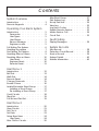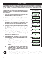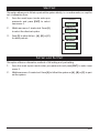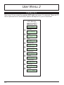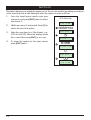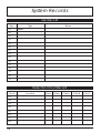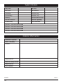
1
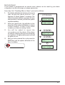
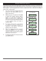
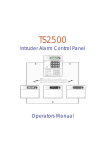
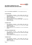
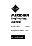
TS590 Intruder Alarm Control Panel _ ~ SYSTEM OPEN 17:30 01 Jan A 1 2 3 B 4 5 6 C 7 8 9 D ENT 0 ESC Sett ing the Syst em Ent er your pa ss code XXXX th en lea v e th e pro tec t ed a re a. Unsetting the System Go dir e ct ly to t he ke yp ad and en ter you r p as scod e XXXX . Resetting Ent er your pa ss code XXXX f ollow ed by EN T the n 3. Te leph on e you r a lar m com pan y and follow th eir instr uct io ns. ! See U ser Manual A 1 2 3 Part Set BELL TEST WALK TEST RESET B 4 5 6 Part Set NEW CODE CHIME 24 Hr OMIT C 7 8 Part Set ZONE OMIT SILENT D ENT 0 9 ESC FULL SET Operators Manual Contents System Overview Introduction . . . . . . . . . . . . . . 3 Remote Keypads. . . . . . . . . . . . 4 Operating Your Alarm System Introduction . . . . . . . . . . . . . . 5 Passcodes . . . . . . . . . . . . . 5 User Types . . . . . . . . . . . . . . 5 User Menus . . . . . . . . . . . . . 5 Banner Message . . . . . . . . . . 5 Engineer on site . . . . . . . . . . . 5 Full Setting The System . . . . . . . . . 6 Unsetting the system . . . . . . . . . . 7 Part Setting The System . . . . . . . . . 8 Unsetting After an Alarm . . . . . . . . 9 Resetting After an Alarm . . . . . . . 10 User Reset . . . . . . . . . . . . . 10 Engineer Reset. . . . . . . . . . . 10 Remote Reset . . . . . . . . . . . 11 User Menu 1 Introduction . . . . . . . . . . Bell Test . . . . . . . . . . . . Walk Test . . . . . . . . . . . Remote Reset. . . . . . . . . Change Passcode . . . . . . Enable Chime . . . . . . . . Isolate/Re-instate Shunt Group Isolating a Shunt Group . . Re-instating a Shunt Group Omit Circuits . . . . . . . . . Silent Set . . . . . . . . . . . Full Set and Part Set . . . . . . . . . . . . . . . . . . . . . . . . . . . . . . . . . . . . . . . . . . . . . . . . . . . . . . 12 13 14 14 15 16 17 17 17 18 19 19 . . . . . . . . . . . . . . . . . . . . . . . . . . . . 20 21 22 23 24 24 26 User Menu 2 Introduction . . . . . View Circuits . . . . Set Clock . . . . . . Set Date . . . . . . Setup New Users . . User Types . . . . Alter Chime Circuits . 2 . . . . . . . . . . . . . . . . . . . . . . . . . . . . . . . . . . . Alter Shunt Group . . . . Print System Log. . . . . Set-up Part Sets . . . . . View Log . . . . . . . . Log Event Codes . . . . Enable Remote Service . Initiate Service Call . . . Circuit Text . . . . . . . . . . . . . . . . . . . . . . . . . . . . . . . . . . . . . . . . . . . . . . . . . . . . . . . . . . . . . . . 27 28 29 30 31 33 34 35 Fault Finding Display Messages . . . . . . . . . . . 36 System Records User Record . . . . . . . Detection Circuit Record Service Record . . . . . System Details . . . . . Installer Information . . . . . . . . . . . . . . . . . . . . . . . . . . . . . . . . . . . . . . 38 38 39 40 40 System Overview Introduction The TS590 is an advanced security alarm control systems using state of the art electronics to provide comprehensive but flexible protection for both domestic and commercial premises. The system comprises of a number of components linked to a central control unit which is concealed from view but accessible for maintenance. The TS590 can monitor from 6 to 14 detection circuits. Both systems can be operated from up to four remote keypads which may be one of four types. Detection devices such as door contacts or movement sensors are allocated to detection circuits which are identified on the remote keypad displays. A modem can also be connected to the alarm system via the telephone line to allow remote interrogation, programming and resetting of alarms. This feature is known as “Downloading” and is normally performed by the installation company or central station. Each alarm installation is specific to the site and its occupier and may differ from other TS590 installations. This manual describes in detail all the functions and procedures available to the user, however, not all these may be relevant to the way your system is set up. To avoid unnecessary operating errors please discuss the details of the alarm system with your installation company before attempting to use it. Also ensure that the installation company complete the system record sheets at the back of this manual. 3 Remote Keypads Your alarm system can be operated from one or more remote LCD keypads, which will have been strategically located within the protected premises. The LCD remote keypad is a full function keypad and can be used to program, test, set and unset the alarm system. LCD Display - Used to show the system time along with other system messages. Green Power Indicator - Flashes if no mains power is present. Steady when mains power is present. Red Function Indicator - Can be programmed by the alarm company, to indicate a fault, set or part-set etc. Keyboard - Used for operating your alarm system. Cover - Fold-down cover with quick guide operating instructions. 4 SYSTEM OPEN 17:30 01 Jan _ ~ A 1 2 3 B 4 5 6 C 7 8 9 D ENT 0 ESC Setting the System Ent er your pa sscode XXXX th en lea ve th e pro tect ed a re a. Unsetting the System Go dire ct ly to t he ke yp ad and en ter you r p asscod e XXXX . Resetting Ent er your pa sscode XXXX f ollow ed by EN T the n 3. Te leph on e you r a larm com pan y and follow th eir instruct io ns. ! See User Manual A 1 2 3 Part Set B ELL TES T WALK TEST RE SET B 4 5 6 24 Hr OMIT Part Set NE W CODE CHIME C 7 8 Part Set ZONE OM IT SILENT D ENT 0 FULL S ET 9 ESC Operating Your Alarm System Introduction Passcodes Access to the system is gained by entering a 4 digit passcode. Every time you wish to use the system your passcode must be entered correctly. User Types The TS590 can have up to 15 separate users each user is assigned a passcode, and a user level. The user level defines what the user can access within the user menus, for a definition of each user level see “Set-up New Users” page 24. User Menus The system has 2 users menus, with each menu having between 9 and 10 options. User menu 1 is accessed by entering your passcode followed by the [ENT] key. Access to user menus and options will depend on your user level. When a menu option is selected you may abandon the option by pressing the [ESC] key. To leave the user menus and return the system to its original state simply keep pressing the [ESC] key until the display shows “OPEN”. Banner Message The banner message is normally shown on the top line of display when the system is unset or full set. This message is configured by your alarm company and is usually set to the alarm company's name. Engineer on site When your alarm company has an engineer on site and is logged into the system, the keypads will show “ENGINEER ON SITE”. You can continue to operate the system as normal, if required. The message is automatically cleared when a user passcode is entered. 5 Full Setting The System The full setting procedure can be initiated from any remote keypad (if more than one is fitted). Before attempting to full set the alarm system ensure that all movement detectors are unobstructed and all doors, and windows are secure. 1. 2. 3. From the unset (open) mode enter your passcode. After 5 seconds the exit sounder will start and the display will show the remaining exit time. L eav e t h e p re m i s e s b y designated exit route, close final door and press the terminator button (if fitted). system is fully set when the sounder stops. NOTES 6 the the exit The exit LCD Remote SYSTEM OPEN 17:30 01 Jan 1 ? ? ? ? Press ENT to Select Functions 2 Please Exit Now. Time left > 0035 3 SYSTEM SET 17:31 01 JAN w To abandon the setting process any time, simply re-enter your passcode. w If the display shows “9999" at step 2 the system is configured set by exit terminator or on closure of the last exit circuit. w If an attempt is made to full set the system whilst one or more circuits are active (such as a door being open) the display at step (2) will indicate the circuit(s) that are in fault and internal sounder generates an interrupted tone. The fault must be cleared before the setting procedure can be completed. If the fault is still present at the end of the exit time an internal alarm will be generated. If fitted, the external strobe light will flash indicating that the system has “Failed to set”. To prevent this alarm simply re-enter your passcode before the exit timer expires. Unsetting the system The unsetting of the alarm system can be performed at any remote keypad. 1. 2. Enter the premises via the prescribed entry route and proceed directly to the remote keypad. The internal sounders generate an interrupted tone. The display will show the remaining entry time. Enter your 4 digit passcode before the entry timer expires. The internal sounders will stop and the display will show “SYSTEM OPEN”. After 5 seconds the “SYSTEM OPEN” message will disappear and the display will show the time, (date and banner text, LCD only). LCD Remote 1 Enter Your Code Time left > 0015 2 ? ? ? ? SYSTEM OPEN 17:30 01 JAN w If the entry time is exceeded an alarm is generated from the internal sounders and the “Second Entry” timer is started. If at the end of the “Second Entry” timer the alarm system has not been unset a full alarm condition will occur. If the alarm company has set the “Second Entry” timer to zero the full alarm will occur when the first entry timer expires. w If during the entry procedure the user strays from the prescribed entry route and activates a detection circuit a full alarm will occur (internal sounders and external sounders). If the alarm system is fitted with a remote signalling device this will also be triggered. w The alarm system can be programmed with an “Abort” feature which will allow the system to transmit an abort signal to your alarm receiving centre. On receiving this signal your alarm receiving centre will cancel any police action. This feature is controlled by a time delay (normally set to 90 seconds). Following a full alarm condition you must enter your passcode with this time period in order to send the abort signal, if you fail to enter your passcode before the timer expires police action will be taken. NOTES 7 Part Setting The System The TS590 can have up to three predefined part set configurations. Each configuration allows the alarm system to set with one or more circuits isolated. Normally the alarm company will configure each part set option, however the master user may also configure the part sets, providing the alarm company has programmed the alarm system to allow this facility. 1. From the unset (open) mode enter your passcode. 2. Select the required part set mode by pressing [A], [B] or [C]. 3. 4. 8 Either press [ENT] when the display shows the required part set mode or wait for 5 seconds after which the exit sounder will start and the display will show the remaining exit time. Leave the area by the designated exit route, close the final door and press the exit terminator button (if fitted). The system is part set when the exit sounder stops. LCD Remote SYSTEM OPEN 17:30 01 Jan 1 ? ? ? ? Press ENT to Select Functions 2 A or B or C Press ENT to Do part set A ? 3 Please Exit Now. Time left > 0035 4 Part Set A 17:31 01 JAN Unsetting After an Alarm If an alarm has occurred whilst the alarm system is full or part set, the display will indicate the detection circuit that was triggered when you unset the system. Once the cause of the alarm has been established the system must be reset, see “Resetting after an alarm” on page 10. 1. 2. 3. E n t er t h e p re m i s e s v i a t h e prescribed entry route and proceed directly to the remote keypad. The internal sounders generate an interrupted tone. The display will show the remaining entry time. Enter your 4 digit passcode before the entry timer expires. The internal sounders will stop and the display will show the circuit that caused the alarm. LCD Remote 1 Enter Your Code Time Left > 0022 2 ? ? ? ? ALARM 03 17:31.02 01/01 LOUNGE DETECTOR 17:31.02 01/01 Refer to “Resetting After an Alarm” on page 10. w NOTES If circuit text has been programmed then the display on the LCD and Starburst remote keypads will alternate between the circuit number and the circuit text at step (2). 9 Resetting After an Alarm Your alarm company will have programmed the system to be either “User Reset”, “Engineer Reset” or “Remote Reset”, consult your alarm company if you are not sure. User Reset If your system has been programmed as user reset, alarms can be reset by any user that has a valid passcode. From step (3) of “Unsetting After an Alarm”, proceed as follows: 1. 2. Enter your passcode and within 5 seconds press [ESC]. The system is now reset and back in the open mode. After 5 seconds the “SYSTEM OPEN” message will disappear and the display will show the time, (date and banner text, LCD only). LCD Remote ALARM 03 17:31.02 1 01/01 ? ? ? ? ESC 2 SYSTEM OPEN 17:30 01 Jan Engineer Reset If your system is programmed as engineer reset, alarms can only be reset by your alarm company. From step (3) of “Unsetting After an Alarm”, proceed as follows: 1. The display will alternate between the circuit that caused the alarm and the “ C al l En g i n e e r T o R e s e t S y s t e m ” message. The internal sounders will also generate a beep every minute to remind you that the system requires resetting. 2. To s i l en c e t h e b e e p s e n t e r y o u r passcode. 3. Contact your alarm company: 10 LCD Remote ALARM 03 17:31.02 01/01 1 CALL ENGINEER TO RESET SYSTEM 2 ? ? ? ? Remote Reset If your system is programmed as remote reset, alarms can be reset by your alarm company or via the exchange or unique passcodes. From step (3) of “Unsetting After an Alarm”, proceed as follows: 1. The display will alternate between the circuit t hat cau s e d t h e a l a rm a n d t h e “ C a l l Engineer To Reset System” message. The internal sounders will also generate a beep every minute to remind you that the system requires resetting. 2. Enter your passcode, this will silence the beeps and the system will display a unique 4 di gi t n u m b e r. Co n t a c t yo u r a l a r m company or alarm receiving centre: 3. You w i l l b e a s k e d t o re p o r t t h e circumstances of the alarm. If the alarm receiving centre decides you do not require an engineer, a 4 digit remote reset code will be given to you. 4. After you have entered the code press the [ENT] key and the system will return to the open condition. LCD Remote ALARM 03 17:31.02 1 2 01/01 CALL ENGINEER TO RESET SYSTEM ? ? ? ? Remote Reset Quote > ???? 3 ? ? ? ? Reply > ---- 4 ENT SYSTEM OPEN 15:30 01 JAN 11 User Menu 1 Introduction User menu 1 is accessed by entering your passcode followed by [ENT]. There are 12 menu options and access to these options will depend on your access level. LCD Remote ? ? ? ? + ENT User menu 1 Select Option :- 1 Bell Test Sounder. ON> 09 PRESS ESC to end 2 3 4 5 Walk Test Walk Test Press ESC to end Remote Reset Remote Reset Quote> 9472 Change Passcode Change pass code New code > ---Enable Chime Chime ccts are Enabled 6 Omit Shunt Group SYSTEM OPEN 13:30 01 JAN 7 Omit Circuits Omit Circuits Enter CCT No.>-- 8 Silent Set Silent Set ? Enter Group > - 0 Full Set Please Exit Now. Time left > 0010 A B C 12 Part Set A,B,C Please Exit Now. Time left > 0010 Bell Test This option allows you to periodically test the external sounders (bell and strobe) and internal sounders. When selected each device will operate in sequence for nine seconds. 1. 2. 3. 4. From the unset (open) mode enter your passcode and press [ENT] to select user menu 1. Whilst user menu 1 is selected. Press [1] to select the bell test option. The internal sounder operates for 9 seconds, then the external sounder operates for 9 seconds, then the external strobe operates for 9 seconds. LCD Remote SYSTEM OPEN 17:30 01 JAN 1 ? ? ? ? + ENT User menu 1 Select Option :- 2 3 When all three tests are completed, the display shows user menu 1. To return the system to the open mode press [ESC]. 1 Sounder.ON> 09 PRESS ESC to end BELL...ON> 09 PRESS ESC to end Strobe.. ON> 09 PRESS ESC to end User menu 1 Select Option :- 4 ESC SYSTEM OPEN 17:30 01 JAN 13 Walk Test This option allows you to test the function of individual detection circuits without causing an alarm. As each circuit is activated the circuit number and status are displayed and the internal sounders generate a two tone “Chime” sound. Once the test has been completed the tested circuits can be reviewed in numerical order. 1. 2. From the unset (open) mode enter your passcode and press [ENT] to select user menu 1. Whilst user menu 1 is selected. Press [2] to select the walk test option. LCD Remote SYSTEM OPEN 17:30 01 JAN 1 ? ? ? ? + ENT User menu 1 Select Option :- 3. 4. 5. Activate detection circuits in turn by opening doors with alarm contacts and walking in front of movement detectors. When the test has been completed, press the [ESC] key. The display will now automatically scroll through the circuits that were tested in numerical order. The current status of the circuit is also displayed. The [ENT] key can be used to scroll through the tested circuits more quickly, if desired. 2 2 Walk Test Press ESC to end 3 Office Window CCT 14 Active Office Door CCT 12 Active 4 ESC Tested CCTs were Press ESC to end Office Door CCT 12 Healthy Press [ESC] to leave the walk test option and return to user menu 1. To return the system to the open mode press [ESC]. Office Door CCT 14 Healthy ESC User menu 1 Select Option :- 5 ESC SYSTEM OPEN 17:30 01 JAN Remote Reset This option allows the user to reset the system after an alarm by using a “Remote Reset” code. The full procedure is explained in “Resetting After an Alarm” on page 10. 14 Change Passcode This option allows you to change your own passcode. The master users can also add and delete user passcodes, see “Set-up Users” on page 24. 1. 2. 3. 4. From the unset (open) mode enter your passcode and press [ENT] to select user menu 1. Whilst user menu 1 is selected. Press [4] to select the change passcode option. Enter your new passcode then press the [ENT] key. A rising tone indicates acceptance and the system returns to user menu 1. A low tone indicates an error and you will be prompted to re-enter your new code. LCD Remote SYSTEM OPEN 17:30 01 JAN 1 ? ? ? ? + ENT User menu 1 Select Option :- 2 4 Change pass code New code > ---- 3 Change pass code New code > 1212 To return the system to the open mode press [ESC]. ENT User menu 1 Select Option :- 4 ESC SYSTEM OPEN 17:30 01 JAN 15 Enable Chime Detection circuits that have been programmed as “Chime” will generate a two-tone sound when triggered. This option allows you to select one of the four chime options: 1 Disabled Chime circuits are disabled. 2 Enabled Chime circuits are enabled at all times. 3 Enabled in P/Set Chime circuits are enabled when the system is unset or part set. 4 Enabled in Unset Chime circuits are only enabled when the system is unset. 1. 2. 3. 4. 5. From the unset (open) mode enter your passcode and press [ENT] to select user menu 1. Whilst user menu 1 is selected. Press [5] to select the enable chime option. Select the chime option by pressing keys [1] to [4] or by pressing [B] to alternate between all 4 options. LCD Remote SYSTEM OPEN 17:30 01 JAN 1 ? ? ? ? + ENT User menu 1 Select Option :- 5 2 Chime ccts are Disabled 3 1 4 Chime ccts are Enabled When the display shows the required setting press the [ENT] key to accept. A rising multi-tone will be heard and the system is returned to user menu 1. Chime ccts are Enabled in P/Set Chime ccts are Enabled in Unset 4 To return the system to the open mode press [ESC]. ENT User menu 1 Select Option :- 5 ESC SYSTEM OPEN 17:30 01 JAN 16 Isolate/Re-instate Shunt Group One or more circuits can be assigned to the shunt group, this is normally done by your alarm company although the master user can also configure the circuits that are assigned to the shunt group, see “Alter Shunt Group” on page 27. Once a shunt group has been defined this option allows you to isolate and re-instate the circuits that are assigned to the shunt group. Isolating a Shunt Group 1. 2. 3. From the unset (open) mode enter your passcode and press [ENT] to select user menu 1. Whilst user menu 1 is selected. Press [6] to select the isolate/Re-instate shunt group option. The system will automatically return to the open mode and the display will indicate that circuits are isolated. LCD Remote SYSTEM OPEN 17:30 01 JAN 1 ? ? ? ? + ENT User menu 1 Select Option :- 2 6 CCTS ISOLATED 09:45 01 JAN Re-instating a Shunt Group 1. 2. 3. From the “CCT ISOLATED” mode enter your passcode and press [ENT] to select user menu 1. Whilst user menu 1 is selected. Press [6] to select the isolate/Re-instate shunt group option. The system will automatically return to the open mode and the display will indicate that the system is open. LCD Remote CCTS ISOLATED 09:45 01 JUN 1 ? ? ? ? + ENT User menu 1 Select Option :- 2 6 SYSTEM OPEN 17:30 01 JAN 17 Omit Circuits Occasionally it may be necessary to omit detection circuits when setting or part setting the system. This allows the user access to the omitted area(s) when the system is set or part set. It is also possible to omit 24hr or Auxiliary circuits so that access to these areas can be obtained when the system is unset. LCD Remote Only detection circuits that have been programmed by your alarm company as “Omit” can be selected when using this option. 1. From the unset (open) mode enter your passcode and press [ENT] to select user menu 1. Whilst user menu 1 is selected. Press [7] to select the omit circuits option. 2. 3. Select the circuit you require to omit by either entering the circuit number or by using the [A] and [C] keys to scroll up and down through the circuits. 4. When the required circuit number is displayed press the [B] key to alternate between “Armed” and “Omitted”. If a low tone is heard when pressing the [B] key the selected circuit cannot be omitted. 5. When the display shows the required setting for the selected circuit, press the [ENT] key to accept. A rising multi-tone will be heard and the display will show the next available circuit. 6. If required repeat from step (3) for other circuits, When you have selected all the required circuits, press the [ESC] key. a) b) If you have selected 24hr circuits, the system will automatically return to the unset mode and the display will indicate that circuits are isolated. 18 1 ? ? ? ? + ENT User menu 1 Select Option :- 2 7 Omit Circuits Enter CCT No.>- 3 0 3 OR A / C Office Detector CCT 03 Armed 4 B Office Detector CCT 03 Omitted 5 ENT Store Room PIR CCT 04 Armed 6 ESC a CCTS ISOLATED 09:45 01 JAN User menu 1 Select Option :- b 0 A B C Please Exit Now. Time Left > 9999 If you have only selected night circuits, the system will return to user menu 1. From user menu 1 you must press [0] to full set, [A], [B] or [C] for part set. w NOTES SYSTEM OPEN 17:30 01 JAN If you have selected a night circuit to be omitted, you must perform a full or part set whilst the user menu is selected. If you return to system open all selected circuits will be cancelled. Silent Set This option allows you to full set or part set the system silently, i.e. no exit sounder, accept for set confirmation tone. 1. 2. From the unset (open) mode enter your passcode and press [ENT] to select user menu 1. Whilst user menu 1 is selected. Press [8] to select the silent set option. LCD Remote SYSTEM OPEN 17:30 01 JAN 1 User menu 1 Select Option :- 2 3. Press [0] to silent full set , [A], [B] or [C] for silent part set. ? ? ? ? + ENT 8 Silent Set ? Enter Group > - 3 0 A B C Please Exit Now . Time Left > 0025 SYSTEM SET 17:31 01 JAN Full Set and Part Set This option offers an alternative method of full setting and part setting. 1. From the unset (open) mode enter your passcode and press [ENT] to select user menu 1. 2. Whilst user menu 1 is selected. Press [0] to full set the system or [A], [B] or [C] to part set the system. 19 User Menu 2 Introduction User menu 2 is accessed by pressing [ENT] whilst user menu 1 is selected. There are 10 menu options and access to these options will depend on your access level. LCD Remote ? ? ? ? + ENT ENT User menu 2 Select Option :- 1 View Circuits CCT 01 Healthy 2 Set Clock Set Clock > ---- 3 Set Date Set Date > ---- 4 5 Setup User Codes Setup users User No. > -Alter Chime Circuits Alter Chime ccts Enter CCT No.>-- 6 Alter Shunt Group Alter Shunt grp Enter CCT No.>-- 7 Log Printout Omit Circuits Enter CCT No.>-- 8 Configure Part Set Configure Omits for part set A 9 View Event Log PASSCODE 01 09:30.05 01/01 B Circuit Text CCT 01, (B=Edit) 20 View Circuits This option allows you to ascertain the status of each detection circuit, The status for each circuit may be as follows: Healthy The normal status of a detection circuit, i.e. door closed or detector healthy. Active This is the alarm status of a detection circuit, i.e. door open or detector in alarm. Tamper This is the tamper open circuit status of a detection circuit, i.e. alarm cable cut or a cover removed from a detector. Shorted This is the short circuit status of a detection circuit, i.e. alarm cable shorted or damaged. 1. 2. 3. 4. From the unset (open) mode enter your passcode and press [ENT] twice to select user menu 2. Whilst user menu 2 is selected. Press [1] to select the view circuits option.The display will show the status of circuit 01. Select the circuit you require to view by either entering the circuit number or by pressing the [A] and [C] keys to scroll up and down through the circuits. To return the system to the open mode press [ESC] three times. LCD Remote SYSTEM OPEN 17:30 01 JAN 1 ? ? ? ? + ENT ENT User menu 2 Select Option :- 1 2 CCT 01 Healthy 3 CCT 01 Active 4 ESC ESC ESC SYSTEM OPEN 17:31 01 JAN 21 Set Clock This option allows you to adjust the system clock. The clock is used for providing event times in the event log and is also displayed when the system is unset or full set. 1. 2. 3. From the unset (open) mode enter your passcode and press [ENT] twice to select user menu 2. Whilst user menu 2 is selected. Press [2] to select the set clock option. Enter the new time in a 24hr format, e.g. 1700 for 5:00 PM. When the display shows the correct time press [ENT] to accept. LCD Remote SYSTEM OPEN 17:30 01 JAN 1 ? ? ? ? + ENT ENT User menu 2 Select Option :- 2 2 Set Clock > ---- 4. To return the system to the open mode press [ESC] twice. 3 1 7 0 0 Set Clock > 1700 ENT User menu 2 Select Option :- 4 ESC ESC SYSTEM OPEN 17:00 01 JAN 22 Set Date This option allows you to set the system date. It is displayed in a date / month format on all LCD remote keypads. 1. 2. 3. 4. From the unset (open) mode enter your passcode and press [ENT] twice to select user menu 2. Whilst user menu 2 is selected. Press [3] to select the set date option. Enter the new date in a date/month format, e.g. 1806 for the 18th June. When the display shows the correct date press [ENT] to accept. To return the system to the open mode press [ESC] twice. LCD Remote SYSTEM OPEN 17:30 01 JAN 1 ? ? ? ? + ENT ENT User menu 2 Select Option :- 2 3 Set Date > ---- 3 1 8 0 6 Set Date > 1806 ENT User menu 2 Select Option :- 4 ESC ESC SYSTEM OPEN 17:31 18 JUN 23 Setup New Users The TS590 allows up to 15 users to operate the alarm system, each user is assigned a user type and a passcode. User 01 is the master user which has a default setting of 5678. User Types The following user types are available: 1 - Master This user type can full set, part set and unset the system. A master user also has access to all user menus and options providing the alarm company has programmed the master user for full access. If the master user has been programmed for limited access the master user cannot access user menu 2 option 6 (Alter shunt group) and 8 (Configure Part Sets). 2 - Standard This user type can full set, part set and unset the system. A standard user also has access to all the options in user menu 1. 3 - Holiday This user type can full set, part set and unset the system. A holiday user also has access to all the options in user menu 1. However, When the system is next unset by a master user, the holiday passcode is automatically deleted from the system. 4 - Set Only This user type operates in the same way as a standard user, except that it only allows setting and part setting of the system. 5 - Reset Only This user type allows unset alarms such as 24hr, fire, auxiliary to be silenced and reset. The user type also has access to user menu 1 options 1 to 7. 6 - Duress This user type operates in the same way as a standard user, but when the passcode is used a silent “Panic Alarm” is transmitted to the alarm receiving centre. If enabled by your alarm company all users can generate a “Duress” alarm by entering their passcode with the first two digits reversed (e.g. for a passcode of 2580 enter 5280 to generate a “Duress” alarm). 7 - PA Code This user type does not have access to any user menus nor can it be used to set and unset the system. When this user code is entered a “Panic Alarm”' is transmitted to the alarm receiving centre and the external sounder(s) and strobe light(s) are also activated. 8 - Shunt This user type does not have access to any user menus nor can it be used to set and unset the system. When this user code is entered it will isolate a predefined group of detection circuits. When the code is re-entered it will reinstate the group. This user type is displayed as “Access” on the starburst remote keypad. 24 Setup New Users (Cont.) 1. 2. 3. 4. 5. 6. From the unset (open) mode enter your passcode and press [ENT] twice to select user menu 2. Whilst user menu 2 is selected. Press [4] to select the set-up new users option. Enter the user number (02 - 15) that you require to set-up, then press [ENT]. The display shows the current type assigned for the selected user, to change the user type press [1] - [8]. When the display show the required user type press [ENT] to accept. Enter the 4 digit passcode for the selected user, then press [ENT] to accept. A rising multi-tone indicates the new passcode was accepted. A low tone indicates that the passcode entered is not available, re-enter, using a different 4 digit code. The system will return to step 3, if required repeat for other users or press [ESC] three times to return the system to the open mode. LCD Remote SYSTEM OPEN 17:30 01 JAN 1 ? ? ? ? + ENT ENT User menu 2 Select Option :- 4 2 Setup users User No. > -- 3 0 3 ENT Alter user type Not in use 4 1 8 Alter user type Master ENT Change pass code New code > ---- 5 2 5 8 0 Change pass code New code > 2580 ENT Setup users User No. > -- 6 ESC ESC ESC SYSTEM OPEN 17:31 18 JAN 25 Alter Chime Circuits This option allows you to select which detection circuits will cause a chime tone when triggered. Once programmed, users that have access to user menu 1 can select one of the four chime options, see “Enable Chime” on page 17. 1. 2. 3. 4. From the unset (open) mode enter your passcode and press [ENT] twice to select user menu 2. Whilst user menu 2 is selected. Press [5] to select the alter chime circuits option. Select the required circuit by either entering the circuit number or by using the [A] and [C] keys to scroll up and down through the circuits. When the required circuit is displayed, press [B] to alternate between “Silent” and “Chime”. When the display shows the required setting press [ENT] to accept. A rising multi-tone will be heard and the next available circuit is displayed. LCD Remote SYSTEM OPEN 17:30 01 JAN 1 ? ? ? ? + ENT ENT User menu 2 Select Option :- 5 2 Alter Chime ccts Enter CCT NO.>-- 3 0 6 OR A / C Entrance Door CCT 06 Silent 4 B Entrance Door CCT 06 Chime ENT 5. Repeat from step 3 for other circuits or press [ESC] three times to return to the open mode. Loading Bay Door CCT 07 Silent 5 ESC ESC ESC SYSTEM OPEN 17:31 01 JAN 26 Alter Shunt Group This option allows you to define which detection circuits are allocated to the shunt group. Once assigned to the shunt group all circuits within the group can be isolated by any user that has access to user menu 1 option 6 (Omit Shunt Group). The shunt group can also be assigned to a user code (Shunt), this allow the group to be omitted and re-instated by entering a 4 digit passcode. 1. 2. 3. 4. 5. 6. From the unset (open) mode enter your passcode and press [ENT] twice to select user menu 2. Whilst user menu 2 is selected. Press [6] to select the alter shunt group option. Select the required circuit by either entering the circuit number or by using the [A] and [C] keys to scroll up and down through the circuits. When the required circuit is displayed, press [B] to alternate between “Armed” and “Omitted”. When the display shows the required setting press [ENT] to accept. A rising multi-tone will be heard and the next available circuit is displayed. Repeat from step 3 for other circuits or press [ESC] three times to return to the open mode. LCD Remote SYSTEM OPEN 17:30 01 JAN 1 ? ? ? ? + ENT ENT User menu 2 Select Option :- 6 2 Alter Shunt Grp Enter CCT NO.>-- 3 0 9 OR A / C Accounts Office CCT 09 Armed 4 B Accounts Office CCT 09 Omited 5 ENT Canteen D.Tec CCT 10 Armed 6 ESC ESC ESC SYSTEM OPEN 17:31 01 JAN 27 Print System Log The system log stores 700 events. If a printer is connected to your alarm system it is possible to print a selected number of log events. 1. 2. 3. 4. From the unset (open) mode enter your passcode and press [ENT] twice to select user menu 2. Whilst user menu 2 is selected. Press [7] to select the print system log option. Enter the number of events to be printed (001 - 700). Press [ENT] to start the printout. To cancel printout repeat from step 2 and enter “000” for the number of events. To return the system to the open mode press [ESC] twice. LCD Remote SYSTEM OPEN 17:30 01 JAN 1 ? ? ? ? + ENT ENT User menu 2 Select Option :- 2 7 Print System Log No. events> --- 3 1 5 0 Print System Log No. events> 150 ENT User menu 2 Select Option :- 4 ESC ESC SYSTEM OPEN 17:31 01 JAN 28 Set-up Part Sets The TS590 can be configured to have up to three parts set modes (Part Set A, Part Set B and Part Set C). This option allows the master user to configure each part set mode. Within each part set mode you must designate which circuits will remain armed and which circuits will be omitted. When the relevant part set mode is selected the system only arms the circuits that are designated as armed and isolates the circuits that are designated as omitted. 1. From the unset (open) mode enter your passcode and press [ENT] twice to select user menu 2. 2. Whilst user menu 2 is selected. Press [8] to select the set-up part sets option. 3. 4. Select the part set mode you require to set-up by pressing [A], [B] or [C] then [ENT]. Select the required circuit by either entering the circuit number or by using the [A] and [C] keys to scroll up and down through the circuits. LCD Remote SYSTEM OPEN 17:30 01 JAN 1 ? ? ? ? + ENT ENT User menu 2 Select Option :- 2 8 Configure Omits for part set A 3 A or B or C ENT 5. 6. 7. When the required circuit is displayed, press [B] to alternate between “Armed” and “Omitted”. An armed circuit will remain armed when the system part set, an omitted circuit will be isolated when the system is part set. When the display shows the required setting press [ENT] to accept. A rising multi-tone will be heard and the next available circuit is displayed. Repeat from step 3 for other circuits or press [ESC] three times to return to the open mode. Accounts Office CCT 01 Armed 4 A/ C Sales Office CCT 05 Armed 5 B Sales Office CCT 05 Omitted 6 ENT Canteen Door CCT 06 Armed 7 ESC ESC ESC SYSTEM OPEN 17:31 01 JAN 29 View Log The TS590 store up to 700 events in the log. This option allows you to view each event. 1. From the unset (open) mode enter your passcode and press [ENT] twice to select user menu 2. LCD Remote 2. Whilst user menu 2 is selected. Press [9] to select the view log option. 3. The display will show the most recent event, see log event codes. To navigate through the log, use the [A] and [C] keys to scroll backwards and forwards. 1 ? ? ? ? The [B] key can be used to display additional information, including circuit information, for the select event. 2 To return the system to the open mode press [ESC] three times. 3 4. 5. SYSTEM OPEN 07:30 01 JAN + ENT ENT User menu 2 Select Option :- 9 PASSCODE 01 09:30.59 28/04 A/ C ALARM 05 06:30.59 4 28/04 B Office Door 06:30.59 28/04 5 ESC ESC ESC SYSTEM OPEN 17:31 01 JAN 30 Log Event Codes LCD Description AC OFF Mains power removed. AC RESTORED Mains power restored ACTION ALARM Alarm activated when system is part-set. ALARM 01-14 Full alarm from circuit (01-14). AUX/BELL TAMPER Auxiliary tamper activated. AUXILIARY 01-14 Auxiliary circuit activated. BATTERY FAULT Battery fault (voltage below 10.5V). BELL TESTED External bell and strobes tested. CALL BACK No. 01-03 Modem making a call back to remote PC. CCT OMITTED Circuits omitted by the user at time of Setting. CCTS ISOLATED 24Hr group omitted during the unset condition. CCTS TESTED 01-14 The number of circuits tested during Walk Test. CODE TAMPER Code tamper from keypad 01-04 COMMS ACTIVE Plug-on digicom active. COMMS FAILED Plug-on digicom failed to communicate. COMMS SUCCESSFUL Plug-on digicom communicated successfully. DATE CHANGED System Date changed. DEFAULT CODE User passcode (01) reset to 5678 by the engineer. DELAY ALARM 01-14 Delayed alarm during a part-set condition. DURESS 01-15 Duress alarm from user passcode (01-15). ENTRY 01-14 Entry timer started by circuit (01-14). ENTRY ALARM 01-14 Entry timed-out alarm from circuit (01-14). FACTORY RESTART System “Factory Restarted”. FIRE ALARM 01-14 Fire alarm circuit activated. FIRST KNOCK 01-14 The first activation of a Double Knock circuit. FUSE BLOWN 01 Control Panel 12V Auxiliary Fuse blown. KEY POINT 01-14 Key point operation from circuit (01-14). LINE FAULT Telephone line fault detected. LINE RESTORED Telephone line fault restored. MODEM LOCK-OUT Modem failed to communicate. NO EVENT No log event. OMITS REMOVED Previously omitted circuits reinstated. ON-SITE RESTART System “On-Site” restart. 31 LCD Description PA ALARM 01-14 Panic Alarm circuit activated. PA CODE 00-15 Panic Alarm passcode entered (00 = Keypad PA). PANEL LID TAMPER Control panel lid removed. PART SET A/B/C System Part-Set using one of the A, B, or C buttons. PASSCODE 00-15 User passcode entered. (00-15). REM REMOVED 01-04 Remote Keypad removed from system. REM SERVICE CALL Remote service call via “Lineload” software and PC. REM TAMPER 01-04 Remote Keypad cover removed. REMOTE ADDED 01-04 Remote Keypad added to the system. REMOTE RESET System reset by “Remote Reset” passcode. SERVICE CALL END Remote service call finished. SERVICE REQUIRED Service required SET FAIL System failed to Set. SYSTEM OPEN System fully unset. SYSTEM RE-ARMED System re-armed all healthy circuits. SYSTEM SET System fully set. TAMPER 00 Short circuit on ID loop. TAMPER 01-14 Tamper alarm from circuit. TEST CCTS OFF All circuits taken off “Test” TEST FAIL 01-14 Circuit failed during “Test”. TIME CHANGED System time changed WALK TEST System “Walk Test” selected. 32 Enable Remote Service If your alarm system has been fitted with a modem, the alarm company can dial into the system and remotely read and write data from the control panel. For added security, your alarm system can be programmed so that a master user has to authorise the writing of data to the control panel. 1. 2. 3. 4. 5. From the unset (open) mode enter your passcode and press [ENT] twice to select user menu 2. Whilst user menu 2 is selected. Press [0] to select the enable remote service option. If a low tone is heard your system has either been configured so that remote servicing is always enabled or your system does not have a modem fitted. The display will show the current status of remote servicing (Enabled or Disabled). Press [B] to alternate between the two options. When the display shows the required setting press [ENT] to accept. A rising multi-tone will be heard and the system will return to user menu 2. LCD Remote SYSTEM OPEN 09:30 28/04 1 ? ? ? ? + ENT ENT User menu 2 Select Option :- 2 0 Remote Call Back Enabled 3 B Remote Call Back Disabled 4 ENT User menu 2 Select option:- 5 ESC ESC SYSTEM OPEN 09:31 28/04 To return the system to the open mode press [ESC] twice. 33 Initiate Service Call If your alarm system has been fitted with a modem it is possible for a master user to initiate an upload sequence to a remote site (normally the alarm company). Once the communication link is established, the remote site can read and write data from the control panel. 1. 2. 3. From the unset (open) mode enter your passcode and press [ENT] twice to select user menu 2. SYSTEM OPEN 17:30 01 JAN Whilst user menu 2 is selected. Press [A] to select the Initiate remote service call option. If a low tone is heard your system does not have a modem fitted. 1 ? ? ? ? Press [1] - [3] to select call-back telephone number 1 -3. 2 4. When the display shows the required telephone number press [ENT] to initiate the call-back sequence. 5. The system will automatically return to the open mode. 34 LCD Remote + ENT ENT User menu 2 Select Option :- A Call Number 1 0181 12345678 3 4 1 = Call No.1 2 = Call No.2 3 = Call No.3 ENT SYSTEM OPEN 17:31 01 JAN Circuit Text Each detection circuit can have up to 16 characters of text assigned to it. This option allows you to program / edit the circuit text. Text Editing Keys LCD Remote SYSTEM OPEN 17:30 01 JAN 1 ? ? ? ? + ENT ENT User menu 2 Select Option :- 2 B 1 A 2 E 3 I 4 O 5 U 6 0 (zero) 7 Move cursor left 8 Change case ENT Accept text A = Next circuit C = Previous circuit 4 B = Edit text Office Detector ^CT 01, (B=Edit) 5 ESC Abandon text editing A Up the alphabet B Change cursor C Down the alphabet Office Detector CCT 01, (B=Edit) 3 0 Space 9 Move cursor right Cursor Types ^ | This is the normal text cursor. Use the text editing key as shown above. This is the number cursor. Use the numbered keys 0 - 9 to enter numeric data. Cursor Use keys to edit text ENT Office Door CCT 01, (B=Edit) 6 ESC ESC ESC SYSTEM OPEN 17:31 01 JAN 1. From the unset (open) mode enter your passcode and press [ENT] twice to select user menu 2. 2. Whilst user menu 2 is selected. Press [B] to select the circuit text option. 3. Select the required circuit by either entering the circuit number or by using the [A] and [C] keys to scroll up and down through the circuits. 4. When the display shows the required circuit press [B] to edit the text, the text cursor will appear at the bottom left hand position on the display. 5. Use the keys to edit the text. When the display shows the required text press [ENT] to accept. 6. Repeat from step 3 for other circuits or press [ESC] three time to return to the open mode. 35 DELAY ALARM 05 17:30 01 Jan Fault Finding Display Messages Displays Description 01 Jan There is no mains power to the control panel and the alarm system is now running on its standby battery. The system will also generate a chime tone every minute to warn you that the fault exists, to silence the chime tones simply enter your passcode. If the mains power is not restored you may not be able to set the alarm system. If the fault persists the standby battery will eventually run flat. Contact your alarm company for further advice. ALARM 05 17:30 01 Jan A full alarm has occurred from a detection circuit (circuit 05). This message is normally display after unsetting the alarm system. Before the system can be set again the alarm system must be reset, see “Resetting After an Alarm” on page 10. AUXILIARY 06 17:30 01 Jan An auxiliary alarm has occurred from a detection circuit (circuit 06). The type of alarm is silent and will activate the appropriate outputs. To reset the alarm simply enter your passcode followed by [ESC]. AUX/BEL TAMPER 17:30 01 Jan The control panel auxiliary or bell tamper circuits have been activated. If the fault is not cleared you will not be able to set the alarm system. To silence the alarm simply enter your passcode. Contact your alarm company for further advice. BATTERY FAULT 17:30 01 Jan The alarm system standby battery has developed a fault, normally because the system mains power is not present. If the fault is not cleared you will not be able to set the alarm system. To silence the alarm simply enter your passcode. Contact your alarm company for further advice. CCTS ISOLATED 17:30 01 Jan One or more circuits have been isolated from the system. For full details refer to “Isolate / Re-Instate Shunt Group” on page 18. CODE TAMPER 02 17:30 01 Jan A passcode has been incorrectly entered more than four times at a remote keypad (keypad 02). To silence the alarm enter a correct passcode. To reset the alarm simply enter your passcode follows by [ESC]. AC OFF 17:30 DELAY ALARM 05 17:30 01 Jan ENTRY ALARM 01 17:30 01 Jan 36 A delayed full alarm has occurred from a detection circuit (circuit 05). This message is normally display after unsetting the alarm system. Before the system can be set again the alarm system must be reset, see “Resetting After an Alarm” on page 10. An entry time out alarm has occurred from a detection circuit (circuit 01). This is normally caused when the entry procedure is started and the system is not unset before the timer expires. Before the system can be set again the alarm system must be reset, see “Resetting After an Alarm” on page 10. Display Messages (Cont.) Displays Description FIRE ALARM 07 17:30 01 Jan A fire alarm has occurred from a detection circuit (circuit 07). The internal sounder will generate a distinctive fire alarm tone and the external sounder is pulsed on and off. To silence the alarm simply enter your passcode. To reset the alarm simply enter your passcode again followed by [ESC]. FUSE BLOWN 01 17:30 01 Jan The auxiliary supply used for powering detection devices has blown its fuse. You will not be able to set the alarm system until the fault is rectified. Contact your alarm company for further advice. PA ALARM 08 17:30 01 Jan A panic alarm (PA) has occurred from a detection circuit (circuit 08). To silence the alarm simply enter your passcode. Reset the panic alarm device if required (normally with a key). To reset the alarm simply enter your passcode again followed by [ESC]. PA CODE 15 17:30 01 Jan A panic alarm (PA) passcode has been entered at a remote keypad by a user (user 15). To silence the alarm simply enter your passcode. To reset the alarm simply enter your passcode again followed by [ESC]. PANEL LID TAMPER 17:30 01 Jan The lid of the control panel has been removed. If the fault is not cleared you will not be able to set the alarm system. To silence the alarm simply enter your passcode. Contact your alarm company for further advice. PHONE LINE FAULT 17:30 01 Jan REM TAMPER 01 17:30 01 Jan SET FAIL 17:30 01 Jan SYSTEM IS BUSY PLEASE WAIT. TAMPER 02 17:30 01 Jan Your alarm system is fitted with a remote signalling device which is reporting a telephone line fault. The system will also generate a chime tone every minute to warn you that the fault exists, to silence the chime tones simply enter your passcode. If the fault is not cleared you may not be able to set the alarm system. If the fault persists, contact your alarm company for further advice. The lid of a remote keypad has been removed (remote 01). If the fault is not cleared you will not be able to set the alarm system. To silence the alarm simply enter your passcode. Contact your alarm company for further advice. The system has failed to set. This normally caused by a circuit being left open at the time of setting. Check that all circuits are healthy before attempting to set the alarm system. Another user is operating the alarm system from another remote keypad. When they have finished all remote keypads will revert to normal operation. A tamper alarm has occurred from a detection circuit (circuit 02). Normally caused by removing the cover from a movement sensor or a break in the circuit cabling. To silence the alarm simply enter your passcode. If the fault is not cleared you will not be able to set the alarm system. Contact your alarm company for further advice. 37 System Records User Record User 01 Type Name Master 02 03 04 05 06 07 08 09 10 11 12 13 14 15 Detection Circuit Record Circuit 01 02 03 04 05 06 07 08 38 Location Omit Chime P.Set A P.Set B P.Set C Detection Circuit Record (Cont.) Circuit Location Omit Chime P.Set A P.Set B P.Set C 09 10 11 12 13 14 Service Record Date Engineer Action 39 System Details Entry Time Exit Time Bell Delay Bell Duration Full Set By Part Set A by Part Set B by Part Set C by Reset by Allow set with line fault Set with mains off Remote signalling Downloading User Authorised Remote 1 Function Indicator Remote 2 Function Indicator Remote 3 Function Indicator Remote 4 Function Indicator Installer Information Installation Engineer: Alarm Company: Address: Telephone No.: Alarm Receiving Centre: Telephone No.: Date Installed: 496859 40 Issue 1