1
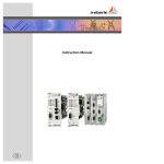
Operating manual
GPS satellite receiver
for world wide application
Versions:
Article Number
111.9024.45
111.9024.46
111.9024.47
111.9024.48
g
Auxiliary Voltage
H1: AC/DC 88V...264V
H2: DC 18V...72V
H1: AC/DC 88V...264V
H2: AC 18V...72V
GPS-Clock
Interface
D2: RS485
D2: RS485
D1: RS232
D1: RS232
We take care of it.
Note:
Please note that this operating manual cannot describe the latest version of the device in
all cases. For example, if you download a more recent firmware version from the internet,
the following description may no longer be accurate in every point.
In this case, either contact us directly or refer to the most recent version of the operating
manual, available on our website (www.a-eberle.de).
A. Eberle GmbH & Co. KG
Aalener Straße 30/32
D-90441 Nuremberg
Tel.: 0911 / 62 81 08 0
Fax: 0911 / 62 81 08 96
E-Mail:
[email protected]
Internet:
www.a-eberle.de
A.-Eberle GmbH & Co. KG cannot be held liable for any damage or losses resulting from
printing errors or changes to this operating manual.
Furthermore, A. Eberle GmbH & Co. KG does not assume responsibility for any damage or
losses resulting from defective devices or from devices altered by the user.
Page 2
Content
1.
General Information....................................................................................................... 4
2.
Operating Principles ....................................................................................................... 4
3.
Installation and Start-up ................................................................................................. 4
3.1
Generals ....................................................................................................................................4
3.2
Installation site for the antenna ...............................................................................................5
3.3
Installing the antenna cable ......................................................................................................5
4.
Electronic connection, DCF- output, Data protocol .......................................................... 6
4.1
Overview of GPS electronic.......................................................................................................7
4.2
Overview 111.9024.45 ..............................................................................................................8
4.3
Overview 111.9024.46 ..............................................................................................................9
4.4
Overview 111.9024.47 ........................................................................................................... 10
4.5
Overview 111.9024.48 ........................................................................................................... 11
5.
Time zone map..............................................................................................................12
6.
Setting up the system ....................................................................................................13
6.1
Setting of time zone ............................................................................................................... 13
6.2
Setting the Daylight Saving Time Changes ............................................................................. 14
6.3
Setting example for Germany ................................................................................................ 16
7.
RS232 data protocol ......................................................................................................17
8.
Technical data ...............................................................................................................17
9.
Drilling Template...........................................................................................................18
10.
Regulations, norms, guidelines ......................................................................................19
11.
Trouble shooting ... what to do if? .................................................................................19
12.
Warning and security hints ............................................................................................20
Content
Page 3
We take care of it.
GPS RECEIVER WITH SIMULATED DCF77 OUTPUT
1.
General Information
The Global Positioning System (GPS) is a satellite system developed in the USA and based
on the NAVSTAR satellites made by Rockwell. With this system, it is possible to receive exact time information anywhere in the world, anytime.
To meet these requirements, it was necessary to position a total of 24 satellites in 6 almost
circular orbits. The satellites’ orbits are inclined at 55° to the equator with an orbital period
of about twelve hours – corresponding to an orbital altitude of 20,183 km. These satellites
are now in operation. Each satellite has a mass of about 430 kg and contains a transmitter,
a receiver, an antenna, an atomic clock for maximum accuracy and a control system for the
satellite’s functions. The principal applications of the GPS system are for fixing positions and
as an aid to navigation.
2.
Operating Principles
Once the GPS system is switched on, it first has to receive and evaluate valid data from the
satellites in its line of sight. This start-up phase may take as little as 2 – 3 minutes if reception conditions are favourable. However, as long as half an hour may be needed if there is a
poor line of sight to the horizon. This start-up phase is also influenced by the configuration
the satellites are in at any particular time. It is impossible to fix a position or obtain time information with fewer than three satellites. The red LED “GPS IS WORKING...” flashes while
the satellite signals are being received. When the unit subsequently commences continuous
operation, this light-emitting diode only flashes when the number of satellites being received falls below three.
It is simple to set up the system and the procedure does not require any particular specialist knowledge. The daylight saving time changes (start and finish) and the time zone can be
set using slide switches.
3.
Installation and Start-up
3.1
Generals
The high frequency of the GPS signal (approx. 1.5 GHz) means an outdoor aerial is always
necessary for receiving GPS satellite data. The antenna must not have any directional characteristics because it needs to receive data from all directions. Consequently, boosting the
reception characteristics of the antenna by shaping it mechanically as in the case of a parabolic antenna, for example, is not a viable option.
This means the signal magnitude at the antenna output is below the general background
noise level. An extremely low-noise pre-amplifier is therefore connected to the antenna input to make it possible to evaluate the signals.
The antenna should have a clear “line of sight” to the entire horizon to guarantee that the
GPS reception will be as continuous as possible. The start-up phase may take a long time if
the reception arc is obstructed by objects or buildings, depending on the configuration of
the satellites. As a result, the antenna should be set up where the maximum possible clear
line of sight to the horizon is guaranteed. In general, the more of the sky you can see from
the installation site, the quicker the GPS clock will be radio-synchronized and the longer it
will remain so.
Page 4
General Information
3.2
Installation site for the antenna
The GPS antenna is located in the control unit housing when the unit is delivered.
Please observe the instructions below if the reception conditions make it necessary to install the antenna separately. The length of the antenna cable is about 5 m.
Poor location
(activation not possible or takes long time)
Good location
(activation in 2-3 minutes)
Adequate location
(may take several hours)
3.3
Installing the antenna cable
Do not route the antenna lead adjacent to other HF, control or power current cables. Interference from these cables could disrupt GPS reception because of the extremely low power
of the received signal. Take particular care when routing the antenna cable.
Please observe the following points:
0 Do not get the antenna plug dirty and do not damage it. Protect it with plastic foil
before pulling the cable through a wall, for example.
0 Do not bend the antenna cable around sharp corners.
0 Do not exceed the bending radius.
0 Do not squash the antenna cable and do not damage the insulation.
Installation and Start-up
Page 5
We take care of it.
Caution!
Extremely powerful voltage or current spikes may occur when outdoor antennas are
used during thunderstorms. These spikes represent a risk of severe or even irreparable
damage not only to the unit connected directly to the antenna but also to other downcircuit units.
The unit should be incorporated into the building’s lightning protection system in order
to avoid suffering costly damage and concomitant costs.
The lightning protection system may only be installed by qualified professionals.
4.
Electronic connection, DCF- output, Data protocol
Consistent with the products in the REGSys™ range, the GPS receiver is available in two variations for different voltage supplies. (See: Technical Data)
1 It is connected using the terminals marked L, N and PE. Only an electrician is allowed to
do this.
The GPS receiver allocates three different output signals.
0 DCF Pulse Output at RS232 Level:
A DCF signal, at RS232 level, is output at the DCF and GND terminals. To synchronise,
for example, a REG-DTM per GPS, the GND terminals must be connected to the GND,
and the DFC terminal must be connected to the RXD of a RS232 interface controller.
The settings needed for synchronisation are described in the user manual of the corresponding device.
0 DCF Pulse Output at RS485 Level (Timebus)
A DCF signal, at RS485 level, is output at the DCF-EA+ and DCF-EA- terminals. To synchronise, for example, a PQI-DATM via GPS, the devices must be connected as follows:
0
0
Page 6
GPS Radio Clock
PQI-DA
DCF-EA+
“A” to connection X6, No. 47
DCF-EA-
“B” to connection X6, No. 48
GND
“GND” to connection X6, No. 50
The settings needed for synchronisation are described in the user manual of the corresponding device.
Termination of the bus should be carried out as described in the user manual of the particular device, and is not dependent on the connection of a GPS radio clock to the bus.
DCF Pulse Output at RS485 Level (Timebus)
A DCF signal, at RS485 level, is output at the DCF-EA+ and DCF-EA- terminals. To synchronise, for example, a PQI-DTM per GPS, the DCF-EA+ terminals must be connected to
the “Time in A”, and the DCF-EA- terminal must be connected to the “Time in B” of the
PQI-D. The settings needed for synchronisation are described in the user manual of the
corresponding device.
Data Protocol at RS232 Level:
A data protocol for a serial RS-232 port is transmitted via the terminals TxD and GND.
The contents of the data are time, day of the week and date. The data format of interface is set at 9600 baud rate, 8 bits, 1 stop bits, Parity odd.
Electronic connection, DCF- output, Data protocol
4.1
Overview of GPS electronic
GPS antenna input
GPS Receiver Module
Control LED for
DCF signal
RS485
DCF Pulse Output
UTC + or – x hour
North-, South hemisphere
Time zone switch
1...12 hours
Sunday (1...5)
End DST
–1h
Month (1...12)
Sunday (1...5)
Begin DST
+1h
Month (1...12)
RS232 / V24
Data- and DCF
Pulse Output
Power Supply
Module
Fuse
LED flushes
permanent =
GPS Time is OK
Power supply
connector 230V~ 50Hz
Electronic connection, DCF- output, Data protocol
LED blinks = no time reception, no reception
Page 7
We take care of it.
4.2
Overview 111.9024.45
Auxiliary Voltage
H1: AC/DC 88V...264V
Europlug
Interface
D2: RS485
EA + / gn
EA - / ws
GND / br
Cable Lengths
GPS - Antenne:
5m
Auxiliary Voltage: 2,5m
RS485: 5m (max.1200m)
Page 8
Electronic connection, DCF- output, Data protocol
4.3
Overview 111.9024.46
Auxiliary Voltage
H2: DC 18V...72V
+ / br
- / bl
Interface
D2: RS485
EA + / gn
EA - / ws
GND / br
Cable Lengths
GPS - Antenne:
5m
Auxiliary Voltage: 2,5m
RS485: 5m (max.1200m)
Electronic connection, DCF- output, Data protocol
Page 9
We take care of it.
4.4
Overview 111.9024.47
Auxiliary Voltage
H1: AC/DC 88V-264V
Europlug
Interface
D2: RS232
SUB-D Plug
Pin2: RXD (DCF)
Pin3: TXD
Pin5: GND
Pin7: RTS
Adapter
RXD / gn
TXD / sw
RTS / rt
GND / ws
Cable Lengths
GPS - Antenne:
5m
Auxiliary Voltage: 2,5m
RS232: 5m (max.15m)
Page 10
Electronic connection, DCF- output, Data protocol
4.5
Overview 111.9024.48
Auxiliary Voltage
H2: DC 18V...72V
+ / br
- / bl
Interface
D2: RS232
SUB-D Plug
Pin2: RXD (DCF)
Pin3: TXD
Pin5: GND
Pin7: RTS
Adapter
RXD / gn
TXD / sw
RTS / rt
GND / ws
Cable Lengths
GPS - Antenne:
5m
Auxiliary Voltage: 2,5m
RS232: 5m (max.15m)
Electronic connection, DCF- output, Data protocol
Page 11
We take care of it.
5.
Page 12
Time zone map
Time zone map
6.
Setting up the system
6.1
Setting of time zone
The time zone setting is made using the DIP switches marked TIME ZONE.
Areas with special time zones +0,5h
North Hemisphere (off) or
South Hemisphere (on)
Location west (-) off or
east (+) on from UTC /
GMT (Greenwich)
Time zone switch
The reference time zone (time zone 0) is UTC (Prime Meridian or Greenwich Mean Time).
The unit is supplied set up for the time zone +1 (Central European Time).
Refer to the map of the world to determine the time zone corresponding to your location
and set the switches in accordance with the table below.
Use the TIME -/+ DIP switch to specify whether you are east or west of the Prime Meridian.
The default setting is east.
In some countries, the time difference to the adjacent time zone is only half an hour rather
than a full hour (refer to the map of the world). The 0.5 h switch must be set to ON if the
GPS receiver is used in any of these countries. The switch is set to OFF when the unit is delivered.
DIP switch setting TIME ZONE
Time zone
switch 1
switch 2
switch 3
switch 4
0
OFF
OFF
OFF
OFF
1
ON
OFF
OFF
OFF
2
OFF
ON
OFF
OFF
3
ON
ON
OFF
OFF
4
OFF
OFF
ON
OFF
5
ON
OFF
ON
OFF
6
OFF
ON
ON
OFF
7
ON
ON
ON
OFF
8
OFF
OFF
OFF
ON
9
ON
OFF
OFF
ON
Setting up the system
Page 13
We take care of it.
Time zone
switch 1
switch 2
switch 3
switch 4
10
OFF
ON
OFF
ON
11
ON
ON
OFF
ON
12
OFF
OFF
ON
ON
Fault 13
ON
OFF
ON
ON
Fault 14
OFF
ON
ON
ON
Fault 15
ON
ON
ON
ON
If the DIP switches are set to a fault in relation to the time zone setting, the values for the data output will be
arithmetically correct.
If the time zone switches have been incorrectly set, the data output values will be mathematically correct. This
means that there will be time shift outputs of 13, 14 or even 15 hours.
6.2
Setting the Daylight Saving Time Changes
The summer/winter daylight saving time changes are set up using the following DIP switches.
Begin of summer time
End of summer time
*DST = Daylight saving time / Summer time
Use the NORTH/SOUTH switch to specify whether you are in the southern or the northern
hemisphere. The northern hemisphere is set when the unit is delivered.
Set the switch to OFF for the northern hemisphere; set the switch to ON for the southern
hemisphere.
The start and finish of summer time is set as shown in the coding table below.
The switches marked MONTH are used for setting the month of the change and the switches marked SUNDAY are used for specifying on which Sunday in that month the change falls
(1st to 4th Sunday or last Sunday in the month). BEGIN indicates the switches for the start
of summer time and END indicates the end of summer time.
+1h for beginning of summer time and –1h for end of summer time
Page 14
Setting up the system
Setting summer time changeover
Setting the MONTH DIP switches
Month
switch 1
switch 2
switch 3
switch 4
no time changeover
OFF
OFF
OFF
OFF
January
ON
OFF
OFF
OFF
February
OFF
ON
OFF
OFF
March
ON
ON
OFF
OFF
April
OFF
OFF
ON
OFF
May
ON
OFF
ON
OFF
June
OFF
ON
ON
OFF
July
ON
ON
ON
OFF
August
OFF
OFF
OFF
ON
September
ON
OFF
OFF
ON
October
OFF
ON
OFF
ON
November
ON
ON
OFF
ON
December
OFF
OFF
ON
ON
Fault
ON
OFF
ON
ON
Fault
OFF
ON
ON
ON
Fault
ON
ON
ON
ON
Setting the Sunday DIP switches
Sunday im month
switch 1
switch 2
switch 3
no time changeover
OFF
OFF
OFF
First
ON
OFF
OFF
Second
OFF
ON
OFF
Third
ON
ON
OFF
Fourth
OFF
OFF
ON
Fifth or last
ON
OFF
ON
No change is made for summer time if the DIP switches are set to fault.
If the DIL switch has been incorrectly set at +1h or -1h, there will be no time change.
Setting up the system
Page 15
We take care of it.
6.3
Setting example for Germany
0 Please take the time zone from the time zone map
0 Please set the DIP switches according to the setting table
Germany is located in the time zone 1 and north hemisphere. The time difference to UTCtime is positive = +1 hour. The summer time changeover takes place at the last Sunday in
March. The end of summer time takes place at the last Sunday in October.
Step 1:
Setting of time zone
DIP switch 1 of TIME ZONE
OFFSET to ON (UTC +1 hour )
Step 2:
Setting of time difference (+/-)
DIP switch of UTC -/+ to ON.
DIP switch NORTH/SOUTH to OFF
Step 3:
Setting of summer time begin
DIP switch 1 and 2
of MONTH +1 to
ON (Month March)
DIP switch 1 and 3
of SUNDAY to
ON (last Sunday)
Step 4:
Setting of summer time end
DIP switch 2 and 4
of MONTH -1 to
ON (Month October)
DIP switch 1 and 3
of SUNDAY to
ON (last Sunday)
*DST = Daylight saving time / Summer time
Page 16
Setting up the system
7.
RS232 data protocol
Technical Data:
Baudrate:
Data bits:
Stop bits:
Parity:
Handshake:
9600Baud
8
1
odd
none
Data transmission of time, day of the week and date takes place each second.
If the GPS time receiver has failure or no GPS time signal reception, the data transmission is
blocked.
The data transmission takes place in three steps:
1.
transmit a control character (STX)
2.
transmit time, day of the week and date.
3.
transmit a final character ETX
STX
02
time
12:34:56
day of the week
7
Date
31.01.06
ETX
03
Day of the week 1 = Monday…… 7 = Sunday
STX 02hex
ETX 03hex
( : ) 3A hex
( . ) 2E hex
8.
Technical data
GPS-time receiver
Output pulse
Phase position output pulse
100 / 200ms
positive or negative
Power
approx. 3VA
Weight incl. active antenna
approx. 650g
Antenna with magnetic clamp
–
–
–
Cable length
Cable diameter
Connector diameter
5 Meters
3 mm
5 mm
Maximum cable length
–
–
–
–
RS232 Interface → Device
RS485 Interface → Device
Cable entry points
Max. clamp wire diameter
15 Meters (RS232 Specification)
1200 Meters (RS485 Specification)
PG 7
1,5 mm²
Case
Index of protection
Dimensions W x H x D (incl. PG screw joints)
Polycarbonate plastic case
IP65
195 x 80 x 65 mm
Operating temperature
-25 up to +65°C
RS232 data protocol
Page 17
We take care of it.
GPS-time receiver – Feature H1
Operating voltage
AC 85V … 110V … 264V
DC 88V … 220V … 280V
GPS-time receiver – Feature H2
Operating voltage
DC 18V … 60V … 72V
GPS-time receiver – Feature D1
Interface DCF77 Signal
RS 485
GPS-time receiver – Feature D2
Interface DCF77 Signal
Versions:
Article Number
111.9024.45
111.9024.46
111.9024.47
111.9024.48
9.
Page 18
Auxiliary Voltage
H1: AC/DC 88V...264V
H2: DC 18V...72V
H1: AC/DC 88V...264V
H2: AC 18V...72V
RS 232
Interface
D2: RS485
D2: RS485
D1: RS232
D1: RS232
Drilling Template
Drilling Template
10.
Regulations, norms, guidelines
The appliance is equivalent the following norms;
0 EN 60950-1:2001 about security of appliances of information technology and general
requirement.
0 EN 61000-6-1:2001 about electromagnetic compatibility
0 EN 61000-6-3:2001 EMV special basic norm for the house use and similar applications.
This product meets the EG Guidelines
0 73/23/EWG dated 29.04.2004 (low voltage guidelines)
0 89/336/EWG dated 23.04.2004 (EMV-guideline including amended guideline 92/31/ EWG)
0 93/68/EWG dated 22.07.1993 (labelling guideline)
11.
Trouble shooting ... what to do if?
Power supply line
Please deal with cable to power input carefully. The cable should not be bended or broken.
Damage: If the power supply line is damaged, please disconnect the line and exchange to
new one. If the case is damaged, please send the complete device to the manufacturer.
Protect against water!
The GPS time receiver is not to be used in the water or in the humid area. Especially not
under the power supply of 230V/AC at the device.
The connected DCF clock doesn’t get the correct time.
0 Please check the cable connections to the clock?
0 The polarity of the connection cable is correctly (GND and DCF SIG)?
Please check the signal level of GPS output positive or negative?
0 Output LED blinks in second tact? If not please replace an antenna correctly.
– If yes, there will be a DCF signal output.
– If no, then check if the GPS antenna is connected and in the correct position. If the
GPS antenna is not connected, then a DCF signal output is not possible. (for more
information see points 3.1 and 3.2: ‘Antenna installation location’)
LED „GPS is working“ blinks?
Please be patient for a while. Until the GPS catches the time signal from the GPS satellites,
it takes some minutes, depending on the location.
0 Check the antenna location
0 Possibly search for a better location.
0 Is it possible that the antenna is being blocked by metallic objects?
After the time reception, this LED flushes permanently.
Time reception problem? See under point 3.2 “Installation site for the antenna”.
If you have still problem with the device, please disconnect the power supply and wait for
min. 1 minute. After that please re-start the device again.
Regulations, norms, guidelines
Page 19
We take care of it.
12.
Warning and security hints
Please understand:
The device is inspected before the delivery and is fully functional. Sometimes, the “no function” doesn’t come from the technical defect, for example the interference at the location
of an antenna or not suitable place and so on.
Before you send the device for repairing, please check the function of the GPS at the different location.
Risk of abuse:
The incalculable risks can cause because of not proper uses and is therefore prohibited.
Especially, the case can be opened and the operating characteristics can be changed only in
voltage free condition.
(please see the illustration under point 6 “ setting up the system)
Device changing or modifying
Please do not change the device itself. You will lose the guarantee.
You also have your contribution to environmental protection!
Marking of electrical
and electronic equipment
in accordance with
WEEE 2002/96/EC
Electrical equipment shall not exceed
the household garbage.
After the battery changing,
you are legally obligated to
return the used batteries or
accumulators.
A disposal of the waste is prohibited
Pb / Hg / Cd
Creates batteries are marked with a sign, that describes the ban on the disposal of household garbage. The chemical symbol of the crucial heavy metals is also indicated.
Pb stands for lead, Hg for mercury and Cd for cadmium. Your used batteries or accumulators have to return to the public gatherings (public legal disposal makers), who are obliged
to withdraw. You meet a significant contribution to the environment!
Page 20
Warning and security hints
Notes
Notes
Page 21
A. Eberle GmbH & Co. KG
Aalener Str. 30/32
D-90441 Nuremberg
Tel.: +49 (0) 911 / 62 81 08-0
Fax: +49 (0) 911 / 62 81 08 96
E-Mail: [email protected]
http://www.a-eberle.de
Software - Version:
_______________________________
Copyright by A. Eberle GmbH & Co. KG
All rights reserved.
GPS satellite time receiver – GPS-Clock